EMCIS EA-300 User manual

Serial Number :
EMCIS Bldg., 77 Dukchun-ro, Mahnan-gu, Anyang city, Kyunggi-do,
Korea 14086
TEL : 031) 444-0058 FAX : 031) 465-0058
Website : www.emcis.co.kr E-mail : emcis@emcis.co.kr
ELECTRO-MAGNETIC COMPATIBILITY INSTRUMENTS & SOLUTION
Always read through and comply with the following safety instructions!
EMI Analyzer
Operation Manual
[ EA-300 ]
EMI ANALYZER (EA-300) OPERATION MANUAL
2

EMI ANALYZER (EA-300) OPERATION MANUAL
3
If this equipment develops a fault, contact office of EMCIS at the address
in the operation manual, or your nearest sales or service office.
Certificate of Compliance
Dear Sir ;
We hereby certify that the products are manufactured, inspected, and tested
according to the rule and regulation of EMCIS quality control program
based on ISO9001,version 2008.
With best regards,
EMCIS Co., Ltd.
Quality Control Dept.
EMI ANALYZER (EA-300) OPERATION MANUAL
4
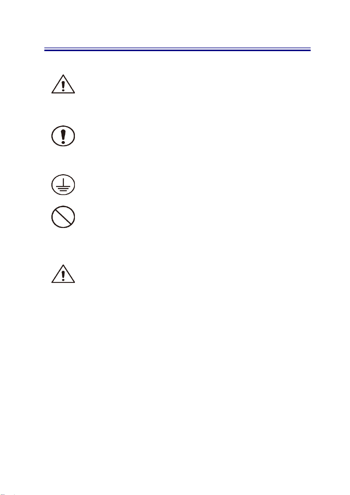
1-1. Safety Symbols
WARNING
Identifies conditions that could result in injury or loss of life
Do not proceed beyond a WARING notice until the indicated condition
are fully understood and met.
CAUTION
Identifies conditions that could result in damage to the equipment
Do not proceed beyond a CAUTION notice until the indicated condition
are fully understood and met.
RPOTECTIVE GROUND TERMINAL
PROHIBITION
1-2. Safety Instruction
Do not touch power cords or the instruments with wet hands, it could be electric shock.
Do not use unspecified power receptacles or power cords for extending. It may result in the
fire or electric shock.
Do not pull or bend power cords by force, it could result in injury or electric shock.
Do not place heavy objects on power cords. Damaged or entangled cords could result in the
fire or electric shock.
Dust around power cords and power receptacles could cause the fire. Keep clean around.
Do not place containers of chemical or water around or on the instrument. If those entering
into the instrument, it could cause the fire or electric shock.
Do not apply many plugs to only on multi outlet at the same time, it could result in over-heating
or the fire.
Do not drop the instrument, it could result in damaged to the instrument or injury.

EMI ANALYZER (EA-300) OPERATION MANUAL
5
1-3. Location & Environment
Location for installation
- Indoor, no direct sunlight, dust free
- No high humidity
- No activated gases
※To keep the instrument well for a long time, it should be used with stable
voltage and temperature
※If using instantly the instrument that was stored in cold temperature for a long
time, because of condensation, it could cause short. Operate the instrument ,
after drying it fully.
* Before using, check the line power voltage .
Unspecified voltage/current could result in damage to the instrument or
the fire.
* Connect to frame ground terminal.
* If no groundedAC receptacle, put to earth Rear panel frame.
EMI ANALYZER (EA-300) OPERATION MANUAL
6
Chapter 2. The Brief of EA-300
1-1
EA-300
EA-300 EMI Analyzer is designed to provide the most effective and powerful instruments in EMI
solution, from measurement, analysis, components selection, and to EMI filter design.
Key Features of EA-300 are
▪EMI Noise Analysis
Measure and analyze the noises from EUT as Differential-Mode and Common-Mode,
respectively, ranged from 9KHz to 300MHz.
: Differential Mode (DM) Noise Current (I
DM
)
: Common Mode (DM) Noise Current (I
DM
)
I
OP
: Main Operating
▪EUT Impedance Analysis
EA-300 measures and analyze EUT impedance at low frequency range (9KHz ~ 500KHz) to be
basic data for Impedance Miss Matching on desired noise attenuation.
▪Components Selection for low frequency noise attenuation
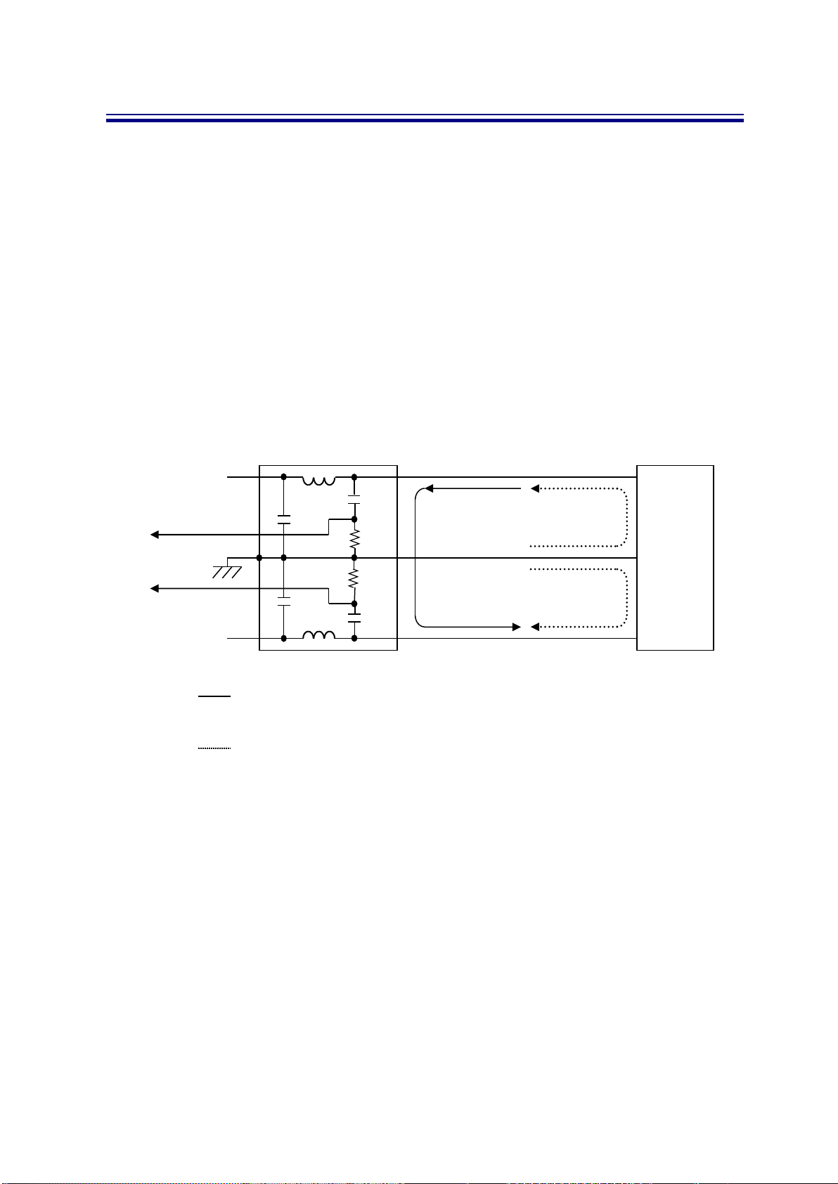
LISN
EMI
Source
(EUT)
ICM/2
IOP+IDM
ICM/2
L
G
N
C
L
L
C
1kΩ
ICM/2+IDM
ICM/2-IDM
1kΩ

EMI ANALYZER (EA-300) OPERATION MANUAL
7
▪Attenuation characteristics of Components Impedance
Matching with EUT impedance, EA-300 provides attenuation characteristics of each noise
modes(Common-Mode and Differential-Mode) and the components ; Common-Mode Choke
Coil, Y-Capacitor, Differential-Mode Coil, and X-Capacitor;
▪Design of EMI Filter
EMI Filter consists of Inductor and Capacitor which are for Common-Mode and/or Differential-
Mode. Only with EA-300, the components for each mode of noises can be analyzed. So, the
properly sized components can be selected for modes can give the fitted filter design.
▪Noise Source Analysis
Using Noise Pick Probe, EA-300 can trace the noise source, the pass-through of noises,
and the characteristics.
EMI ANALYZER (EA-300) OPERATION MANUAL
8
Chapter 3
Construction of EA-300
3-1
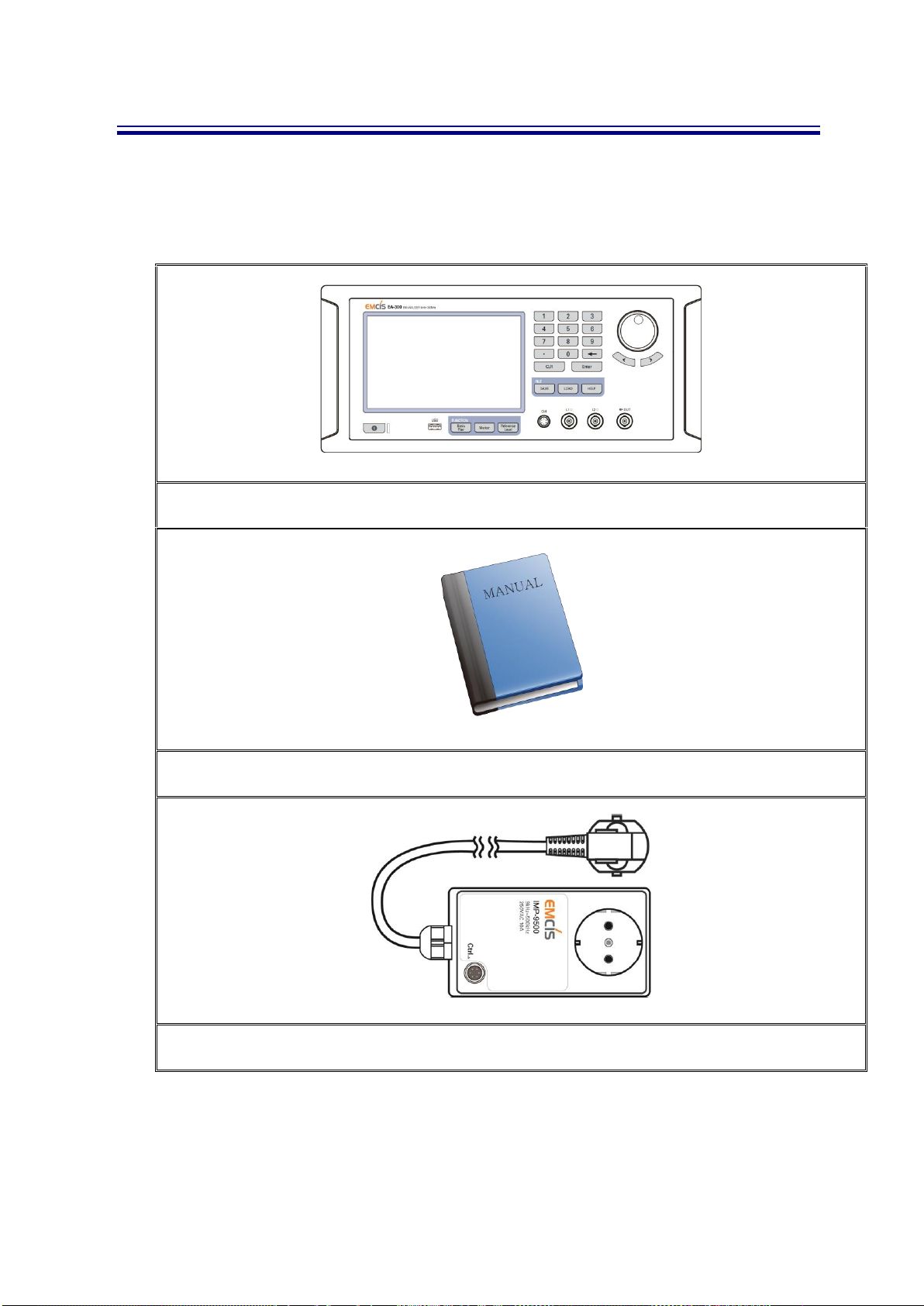
Main Body and Accessories
EA-300
Manual
Impedance Module

EMI ANALYZER (EA-300) OPERATION MANUAL
9
Control Cable
Power Cord
3-2
Optional Accessories
Cable (BNC-MM-140)
Cable (BNC-MM-160)
Cable (BNC-MM-280)

EMI ANALYZER (EA-300) OPERATION MANUAL
10
Chapter 4
Specification
4-1
Specification
▪Frequency Range
1
Test Mode
9kHz~300MHz
2
Analysis Mode
Low Range
9kHz~30MHz
3
High Range
30MHz~300MHz
▪RF INPUT
1
Connecter
BNC Female
50 ohm
2
Max Input Level
110
dBuV
3
Input Sensitivity
10
dBuV
▪RF OUTPUT
1
Connecter
BNC Female
50 ohm
▪CM/DM Separation
1
9kHz~30MHz
40dB Min
Low Range
2
30MHz~300MHz
30dB Min
High Range
▪Insertion Loss
1
9kHz~30MHz
2dB Max
2
30MHz~300MHz
3dB Max
▪MODE
1
Test
Line 1, Line 2
2
Analysis
Common Mode, Differential Mode Selection
▪Input Power
1
Input Voltage
AC 100V~250V
Free Voltage
2
Input Current
50/60Hz 1.19A

EMI ANALYZER (EA-300) OPERATION MANUAL
11
▪Dimension
W[365] x D[330] x H[150](mm)
▪Indicators Power On LED
▪Weight : 9.2kg
▪Optional Accessories
Name
Model
Specification
Application
1
BNC to BNC Cable
BNC-MM-140
BNC to BNC 140mm
Body-LISN connection
2
BNC-MM-160
BNC to BNC 160mm
Body-Spectrum Analyzer connection
3
BNC-MM-280
BNC to BNC 280mm
Body-LISN connection
EMI ANALYZER (EA-300) OPERATION MANUAL
12
4-2
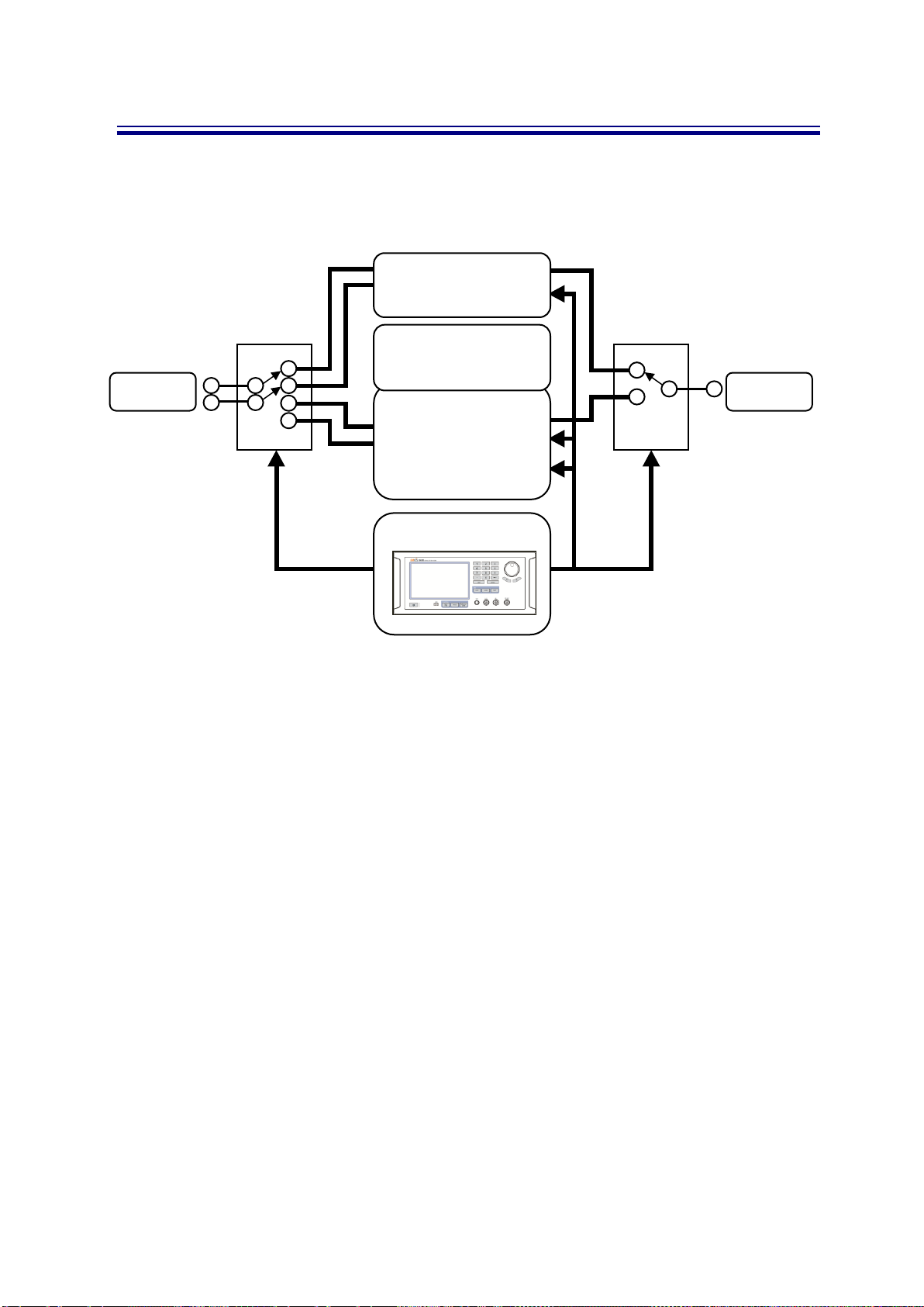
Block Diagram
EA-300 Block Diagram
1.
Signal from Spectrum Analyzer are delivered through two(2) RF INPUT terminal are linked
by Mode Control as ‘Test Mode Module’ and ‘Analyzer Mode Module’, being finally selected
as ‘Test Mode’ and ‘Analyzer Mode’
2.
Analyzer Mode are divided into Common-Mode module and Differential-Mode module.
3.
Each of Common-Mode and Differential-Mode has Low Range and High Range by
frequency.
INPUT
OUTPUT
Test MODE
Module
Low Range
CM/DM Module
High Range
CM/DM Module
Control
Analyzer MODE
Module
EMI ANALYZER (EA-300) OPERATION MANUAL
13
Chapter 5
Description of Body
5-1
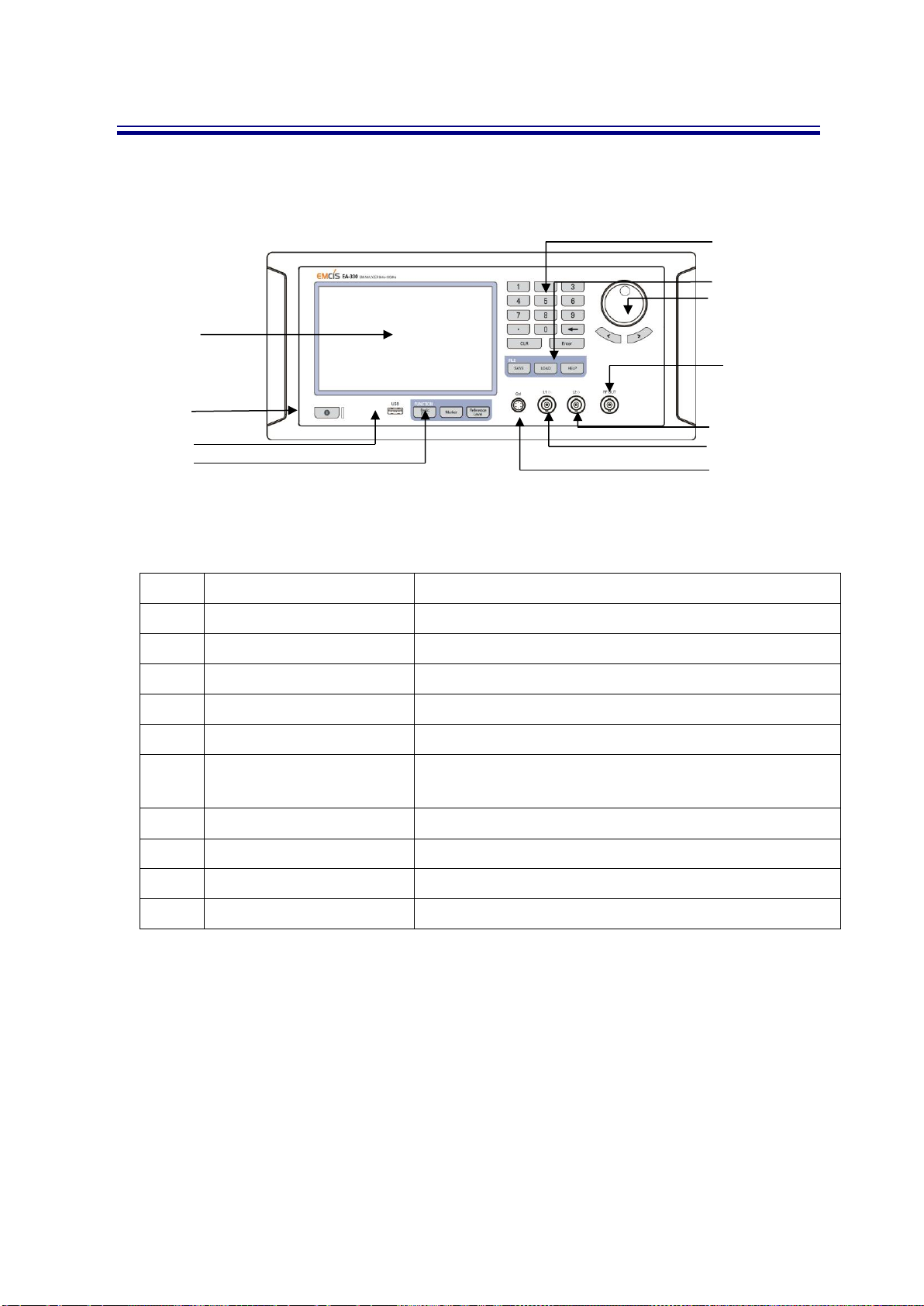
Front Panel
Front Panel
No
Name
Application
1
Key pad
Input the numbers.
2
File Area
Data control ; Save, Load, Help
3
Jog & shuttle
Input data
4
RF Output Connector
Connect RF Output of LISN
5,6
RF Input Connector
Connect to Input of Spectrum Analyzer or Receiver
7
Impedance Module Control
Connector
Control EUT Impedance Module
8
Function Area
Manu/Mode selection/changing like Base Filter, Maker
9
USB
Connect to outer interface
10
Power Button
Front Display On/Off power switch
11
Touch Display
Main Display
11
10
3
4
5
7
6
1
2
8
9

EMI ANALYZER (EA-300) OPERATION MANUAL
14
5-2
Rear Panel
Rear Panel
No
Name
Application
1
Fan
Cooling Fan
2
DVI(Digital Type)
DVI Connector for display
3
LAN Connector
Connect to LAN
4
USB x 4
USB Interface
5
Audio Connector
Support Audio
6
PS/2 Connector
Mouse / Key board
7
Ground Terminal
8
RS-232 Connector
RS-232
9
Main Power Switch
EA-300 Main Power ON/OFF Switch
7
9
8
1
2
3
4
5
6

EMI ANALYZER (EA-300) OPERATION MANUAL
15
5-3
Cable Connection
▪Easy and Quick Cable Connection
Cable connection 1
Connection are done by BNC type cable
But, for spectrum analyzer, N-BNC adaptor is required.
▪In / Output Connector
In/Output Connector
RF Input
: Connector for LISN Output
RF Output
: Connector for Spectrum Analyzer
IN PUT
OUT PUT
EMI ANALYZER (EA-300) OPERATION MANUAL
16
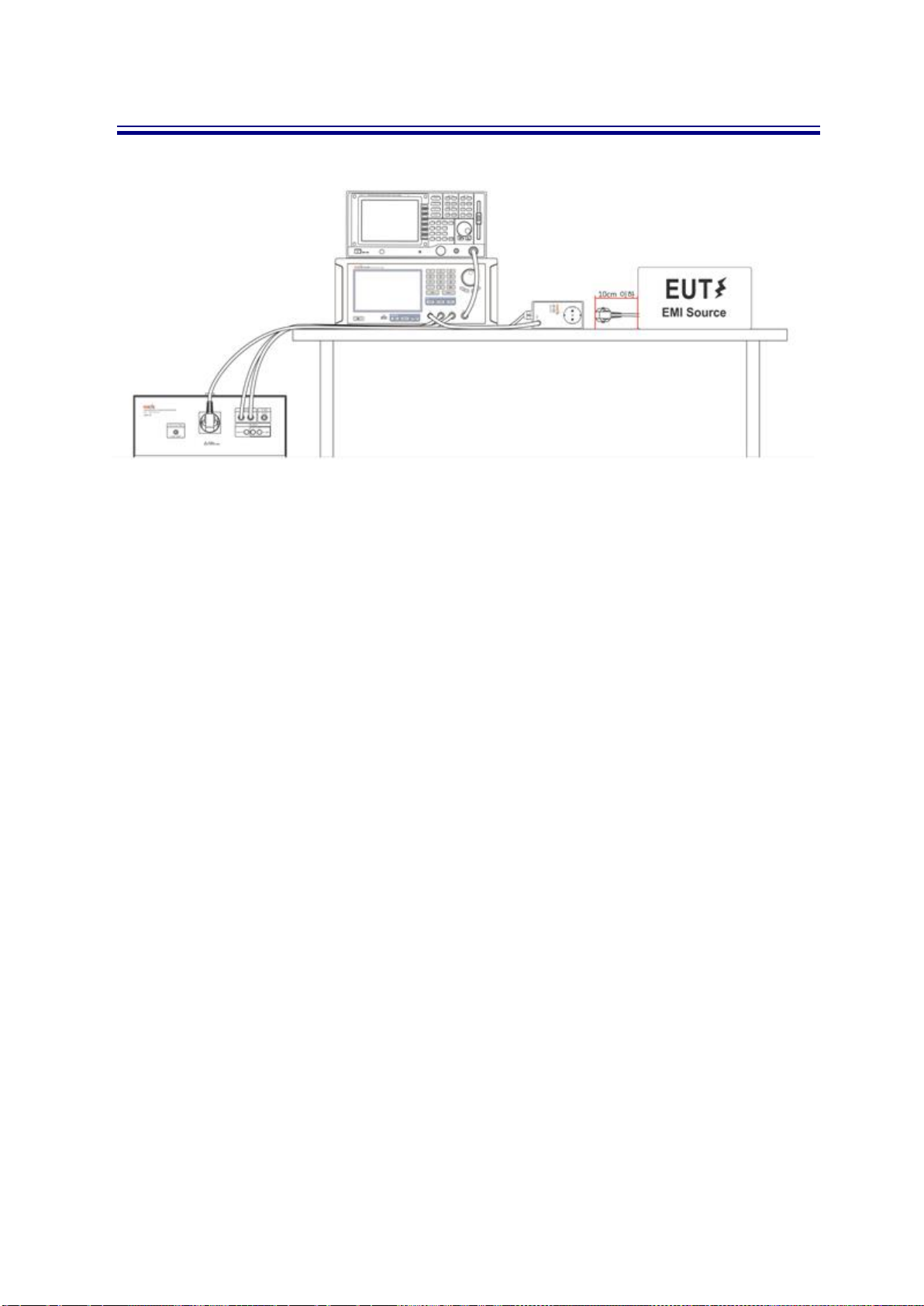
▪Test Table Connection
Cable Connection 2
To avoid cable loss between EA-300 and LISN, recommended strongly shielded
BNC cable. And be noted that the BNC cable should be same length.
EMI ANALYZER (EA-300) OPERATION MANUAL
17
Chapter 6
Details of Panels
6-1
Front Panel Details
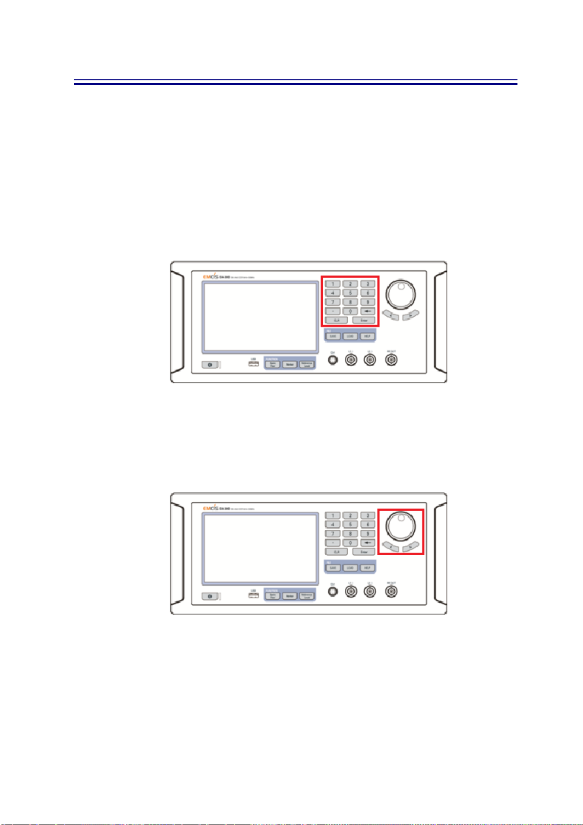
▪Number key
Data Input
Back Space –Erase input Data
Comma –
Clear –Erase all input Data
Enter –
Number key
▪Jog Shuttle and Directional Key
Move Focus and Marker on List condition/Display
Jog Shutte and Directional Key

EMI ANALYZER (EA-300) OPERATION MANUAL
18
▪Save Button
Save the data/displayed screen shot
.
Save Button
▪Load Button
Load the saved Data.
Load Button

EMI ANALYZER (EA-300) OPERATION MANUAL
19
▪Basic Filter Button
Select Basic Filter Function mode
Basic Filter Button
▪Marker Button
Activate Jog shuttle
Marker Button

EMI ANALYZER (EA-300) OPERATION MANUAL
20
Chapter 7
EA-300 Software
7-1
Software
▪Auto Mode and Manual Mode
Current EA-300 is Manual Mode only.
▪Brief of operation
CM : Common Mode
DM : Differential Mode
Select between Test Mode and Analysis Mode
Test Mode measures noises of each Lines, L1, L2
Analysis Mode measures Common-Mode and Differential-Mode of selected line
Analysis Mode is divided as Low Range and High Range by frequency
START
Test Mode
Line1(L1) Line2 (L2)
Analysis Mode
Low CM
Low DM
High CM
High DM
Table of contents
Other EMCIS Measuring Instrument manuals


Popular Measuring Instrument manuals by other brands


Keysight Technologies
Keysight Technologies N5245-60106 Installation note

Airmar
Airmar WeatherStation 200WXRS Owner's guide & installation instructions

SPI
SPI 11-983-4 Operating instructions manual

MRC
MRC CD-4307SD Operation manual

LaserLiner
LaserLiner MultiWet-Finder Plus manual

Simpson
Simpson Falcon F35 Series manual


