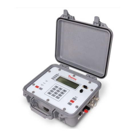
Thermo Electron Polysonics SX40 User manual

Analyze · Detect · Measure · ControlTM
Polysonics SX40
Dedicated Doppler Flowmeter
User Guide
P/N 1-0563-006
Revision G
HDS MESSTECHNIK
Franz-Kissing-Straße 7
58706 Menden
Tel.: 02373 / 1341
Fax: 02373 / 2488
www.hds-messtechnik.de

Polysonics SX40
Dedicated Doppler Flowmeter
User Guide
P/N 1-0563-006
Revision G


2005© Thermo Electron Corporation. All rights reserved.
“Sil-Glyde” is a registered trademark of American Grease Stick Company.
All other trademarks are the property of Thermo Electron Corporation and its subsidiaries.
Thermo Electron Corporation (Thermo) makes every effort to ensure the accuracy and completeness of this
manual. However, we cannot be responsible for errors, omissions, or any loss of data as the result of errors or
omissions. Thermo reserves the right to make changes to the manual or improvements to the product at any time
without notice.
The material in this manual is proprietary and cannot be reproduced in any form without express written consent
from Thermo.

This page intentionally left blank.

Thermo Electron Corporation Polysonics SX40 User Guide ii
Contents
Product Overview..............................................................................................1-1
Introduction........................................................................................ 1-1
Ordering Information ......................................................................... 1-1
Specifications ...................................................................................... 1-2
Performance..................................................................................... 1-2
Physical............................................................................................ 1-2
Functional........................................................................................ 1-3
Approvals ......................................................................................... 1-4
Installation & Wiring........................................................................................2-1
Installing the Transducers ................................................................... 2-1
Mounting the Enclosure...................................................................... 2-4
Wiring ................................................................................................ 2-5
AC Power......................................................................................... 2-5
DC Power........................................................................................ 2-6
Transducers..................................................................................... 2-7
Relays............................................................................................... 2-9
4–20 mA Current Loop (Rev. F or Earlier) .................................... 2-11
4–20 mA Current Loop (Rev. G or Later)...................................... 2-13
Connecting a Switch to Remote Zero Feature................................ 2-14
Operation & Configuration ..............................................................................3-1
The Interface....................................................................................... 3-1
Screen Contrast................................................................................ 3-1
Configuration ..................................................................................... 3-2
Auto Mode....................................................................................... 3-2
Manual Mode .................................................................................. 3-3
HydraScan .......................................................................................... 3-6
Setup Items.........................................................................................................4-1
Reset ................................................................................................... 4-1
Config................................................................................................. 4-1
I/O Test.............................................................................................. 4-1
Relays............................................................................................... 4-1
4–20 mA Loop Calibration .............................................................. 4-1
4–20 mA Loop Test ......................................................................... 4-2
Flow.................................................................................................... 4-2
Rate.................................................................................................. 4-2
Chapter 1
Chapter 2
Chapter 3
Chapter 4

Contents
iii Polysonics SX40 User Guide Thermo Electron Corporation
Max.................................................................................................. 4-2
Flow Menu Items .............................................................................................. 5-1
Setup................................................................................................... 5-1
FFT..................................................................................................... 5-1
Logset ................................................................................................. 5-1
Accessing, Saving, & Loading Log Files............................................ 5-1
Trend.................................................................................................. 5-1
Rate.................................................................................................. 5-1
Max.................................................................................................. 5-1
Troubleshooting & Maintenance................................................................... 6-1
General Troubleshooting .................................................................... 6-1
Learn Mode Warnings ..................................................................... 6-2
Operating Mode Warnings .............................................................. 6-2
Variable Frequency Drives (VFDs)................................................... 6-3
Checking the FFT............................................................................ 6-3
Signal Quality & Strength................................................................... 6-5
General ............................................................................................ 6-6
Maintenance ....................................................................................... 6-6
Replacing the Relays......................................................................... 6-6
Replacing the 4–20 mA Board ......................................................... 6-7
Replacing the Fuse ........................................................................... 6-8
Upgrades............................................................................................. 6-9
Service & Returns ............................................................................... 6-9
Warranty........................................................................................... 6-10
Hazardous Area Installations........................................................................ A-1
Obtaining Pipe ID............................................................................................. B-1
Chapter 5
Chapter 6
Appendix A
Appendix B

Thermo Electron Corporation Polysonics SX40 User Guide 1-1
Chapter 1
Product Overview
Thermo’s Polysonics SX40 Dedicated Doppler Flowmeter generates two
independent ultrasonic signals at different frequencies. By correlating these
frequencies, the instrument automatically identifies and eliminates noise
errors from sources such as variable frequency drives.
In addition, operation of the instrument is enhanced by an Expert System
which allows the flowmeter to automatically “learn” the application
parameters. As a result, the flowmeter can be easily commissioned in a
fraction of the time required to configure competitive ultrasonic
flowmeters.
Refer to the following list of part numbers to order spare parts for your
instrument.
Table 1–1.
Part Number Description
22767-0001 Poly CD, specification sheet, meter installation video CD
1-0563-006 User guide
1-0561-005 HydraScan software manual
01008-0006 RS232 cable, standard serial, 6-ft, female to male, DB9
10241-0003 Hazardous area relay, 3 A, SPDT
10261-0013 Fuse, 1 A, time delay, AC input
10396-0194 Power cord connector, CGB, for 6-ft AC power cord
10605-0001 Pipe strap, SS, 32-inch with 3/8 SS screw
10605-0003 Pipe strap, SS, 67-inch with 3/8 SS screw
10705-0003 Nut driver, 3/8-inch
10808-0002 Coupling compound, silicone RTV108, 2.8 oz
10823-0005 Coupling compound, Sil-Glyde®, 4-oz
20192-0001 SS tag
22061-0001 Heater assembly suitable for -40°F to 140°F (-40°C to 60°C) operation,
100–120 Vac
22061-0002 Heater assembly suitable for -40°F to 140°F (-40°C to 60°C) operation,
220–240 Vac
Introduction
Ordering
Information

Product Overview
Specifications
1-2 Polysonics SX40 User Guide Thermo Electron Corporation
Part Number Description
22204-0003 Mounting feet, set of 4
22262-0006 PCB assembly, 4–20 mA output (applicable with firmware v. 2.03)
22302-0002 PCB assembly, motherboard (specify input voltage)
22366-0002 Cable adapter, dedicated transducer to portable meter
22490-0001 Cable adapter set, portable transducer to dedicated meter
22511-0020 Intrinsically Safe barrier kit, universal
22686-0002 PCB assembly, Doppler
22703-0002 Transducer assembly (set of 2), 30-ft cable length
22705-0002 PCB assembly, CPU
22714-0002 PCB assembly, adapter board
22732-0001 Front panel assembly, includes keypad and display
22801-0002 PCB assembly, 4–20 mA output (applicable with firmware v. 3.03)
22061-0003 Heater assembly suitable for -40°F to 140°F (-40°C to 60°C) operation,
24 Vdc
Velocity Range: 0.2–18 ft/s (0.06–5.5 m/s)
Accuracy: ±1% of velocity full scale
Fluids: Liquids containing particulate or entrained gas bubbles
Pipe Size: 0.5–200 in (12–5000 mm)
Transmitter: NEMA 4X (IP65), flame retardant, fiberglass reinforced
polyester
Transducers
Two encapsulated dual frequency sensor heads suitable for
submersible/underground service
Encased in stainless steel shrouds, with stainless steel straps and quick
clamps
Cable length: 30 ft (9 m)
Weight: 12 lb (5.4 kg)
Dimensions: Refer to the Figure 1–1
Specifications
Performance
Physical

Product Overview
Specifications
Thermo Electron Corporation Polysonics SX40 User Guide 1-3
Figure 1–1.
Outputs: 4–20 mA (into 750 ohms), 12-bit, 5 kV opto-isolated; loop or
self-powered
Optional Relay: 5-A, SPDT, programmable relay; maximum of 4
Power Supply
DC Power: 11–28 Vdc
AC Power: 90–132 Vac or 190–250 Vac (switch selectable), 50/60 Hz
Keypad: 19-key with tactile action
Display: Backlit, 240 x 60 dot, high resolution graphics display
Data Logger
90000-point data logger
Programmable in intervals of 30 s, 1, 5, 15, 30, and 60 min
Programming: Via HydraScan software or integral keypad
Serial Interface: RS232
Functional

Product Overview
Specifications
1-4 Polysonics SX40 User Guide Thermo Electron Corporation
Temperature Range
Transducers: -40°F to 250°F (-40°C to 121°C); coax cable limited to
176°F (80°C)
Electronics: -20°F to 140°F (-29°C to 60°C)
With integral heater: -40°F to 140°F (-40°C to 60°C)
Hazardous Area Certification
Optional: CSA Class I, Div. 2 or Class II, Div. 2
Optional: CSA Intrinsically Safe Class I, Div. 1; Class II, Div. 1; or
Class III, Div. 1
Optional: Intrinsically Safe CENELEC (LCIE)
Approvals

Thermo Electron Corporation Polysonics SX40 User Guide 2-1
Chapter 2
Installation & Wiring
1. Select an installation site:
Keep the following questions in mind when choosing a proper
installation site:
●Is the chosen section of pipe always full of liquid?
●Are there at least 5 pipe diameters upstream and 3 pipe diameters
downstream from any directional changes, pipe joints, or
narrowing/widening of the pipe?
Figure 2–1. Recommended installation locations
Conditions at locations A, B, C, D, and E can interfere with the
transmission of the ultrasonic wave and yield inaccurate or unreliable
flow readings:
●A: Pipe may not be full
●B: Down flow
●C: Too close to elbow
●D: Air collects at the top of the horizontal pipe
●E: Sediment collects at the bottom of the horizontal pipe
Note Selecting the proper installation location is essential to flow
measurement reliability. Each application is unique and may require a
variation of installation locations. ▲
Installing the
Transducers

Installation & Wiring
2-2 Polysonics SX40 User Guide Thermo Electron Corporation
2. Select a transducer orientation:
Refer to Figure 2–2. If your application allows, install the transducers at
the 3 and 9 o’clock locations. Ensure the transducers are parallel to
each other along the pipe circumference.
Figure 2–2. Recommended transducer orientations
3. Attach the transducers to the pipe strap:
a. Use a screwdriver to loosen the mounting screw and slide the lock
back on each transducer.
Figure 2–3.

Installation & Wiring
Installing the Transducers
Thermo Electron Corporation Polysonics SX40 User Guide 2-3
b. Place the pipe strap across the mounting, and slide the lock back
into place.
Figure 2–4.
c. Tighten the screws.
Figure 2–5.
4. Mount the transducers, ensuring the transducers face the same
direction (as shown in Figure 2–6):
a. Wrap the pipe strap around the pipe, and slide the end of the pipe
strap through the tension nut assembly.
b. Pull the strap tightly, and clamp the tension nut down to secure the
strap to the pipe.
c. Loosen the mounting screw of a transducer, and move the
transducer to the 3 o’clock position on the pipe. Tighten the
mounting screw to secure the transducer.
d. Loosen the mounting screw of the second transducer, and move the
transducer to the 9 o’clock position. Tighten the mounting screw
to secure the transducer.
e. Remove the strap from the pipe, and apply sonic coupling
compound to each transducer surface.
f. Reposition the strap on the pipe, placing the transducers in the
proper positions.

Installation & Wiring
2-4 Polysonics SX40 User Guide Thermo Electron Corporation
g. Tighten the tension nut assembly with a 3/8-inch hex nut driver to
secure the strap.
Note Increasing the pipe strap tension improves signal
transmission. ▲
Figure 2–6.
Warning To prevent the possibility of electrical shock and/or damage to
the meter, do not mount the enclosure where it can be submerged or
partially submerged. ▲
1. Locate a sturdy, vertical mounting surface.
2. Remove the meter access cover, and locate the 4 mounting holes (1 in
each corner of the cover).
3. Attach the enclosure to the wall using the mounting screws.
4. Replace the meter access cover.
Note An optional mounting ear package is also available. ▲
Mounting the
Enclosure

Installation & Wiring
Wiring
Thermo Electron Corporation Polysonics SX40 User Guide 2-5
Warning Prevent possible electrical shock and/or damage to the meter:
Disconnect power to the meter PRIOR TO wiring. ▲
Caution Connecting AC power to a DC power meter may damage the
meter. ▲
Note CE certifications require that a switch or circuit breaker be installed
in close proximity to the instrument and be labeled as the instrument
disconnect. ▲
Refer to the following instructions and Figure 2–7 when wiring the
instrument for AC power.
1. Remove the meter access cover.
2. Locate the AC input voltage selector, and turn the switch to 110 or 220
V to match the power line voltage.
3. Locate the L1, L2/N, and GND connections within power input block.
4. Turn the terminal screws on top of the input block counterclockwise to
fully open the wire connections.
5. Make the following connections:
a. Ground wire to GND (CE certification requires less than 1 ohm
between terminal and ground)
b. Hot wire to L1
c. If the input voltage is 110 V, neutral wire to L2/N
d. If the input voltage is 220 V, second hot wire to L2/N
6. Turn the terminal screws clockwise to close them connections.
7. Ensure the wires are securely connected to the input block, and replace
the meter access cover.
W
iring
AC Power

Installation & Wiring
2-6 Polysonics SX40 User Guide Thermo Electron Corporation
Figure 2–7. AC power connections
Later versions of the instrument (those with P/N 22686-0002 Rev. G and
later) have DC operation built into the instrument. Refer to the following
instructions and Figure 2–8.
1. Remove the meter access cover.
2. Locate the power input block, and turn the terminal screws on top of
the input block counterclockwise to fully open the wire connections.
3. Make the following connections:
a. +24VDC to P2 +24
b. 24 VDC return to either of the P2 GND connections
4. Turn the terminal screws clockwise to close them connections.
DC Power

Installation & Wiring
Wiring
Thermo Electron Corporation Polysonics SX40 User Guide 2-7
5. Ensure the wires are securely connected to the input block, and replace
the meter access cover.
Figure 2–8. DC power connections
Warning Prevent possible electrical shock and/or damage to the meter:
Disconnect power to the meter PRIOR TO wiring. ▲
1. Refer to Figures 2–9 and 2–10.
2. Remove the meter access cover.
3. Remove the nut from the transducer cable connector, and draw the
cable through the opening in the meter enclosure.
4. Thread the nut onto the cable connector to the inside of the enclosure.
Transducers

Installation & Wiring
2-8 Polysonics SX40 User Guide Thermo Electron Corporation
5. Tighten the nut to 15 ft-lb of torque using a torque wrench.
6. Locate the XMT (DN), XMTGND, RCV (UP), and RCVGND wire
connections within the transducer I/F block.
7. Turn the screws on top of the transducer block counterclockwise to
fully open the connections.
8. Identify the transducer’s 2 signal wires and 2 braided ground wires.
9. Make the following connections:
a. First signal wire to XMT (DN)
b. First braided ground wire to XMT GND
c. Second signal wire to RCV (UP)
d. Second braided ground wire to RCV GND
10. Turn each screw clockwise to close the connections.
11. Ensure the wire connections are secure, and replace the meter access
cover.
Figure 2–9. Transducer cable seal assembly

Installation & Wiring
Wiring
Thermo Electron Corporation Polysonics SX40 User Guide 2-9
Figure 2–10. Transducer connections
Warning Prevent possible electrical shock and/or damage to the meter:
Disconnect power to the meter PRIOR TO wiring. ▲
Refer to step 10 of “Manual Mode” in Chapter 2 for instructions on relay
configuration.
1. Refer to Figures 2–11 and 2–12.
2. Remove the meter access cover.
3. Locate the 4 relay terminals blocks, and select the relay you are going to
wire.
4. Locate the Normally Closed (NC), Common (C), and Normally Open
(NO) relay contacts on the terminal block.
Relays
Table of contents
Other Thermo Electron Measuring Instrument manuals

Thermo Electron
Thermo Electron 96-09 User manual

Thermo Electron
Thermo Electron Polysonics SX30 User manual

Thermo Electron
Thermo Electron Nicolet 4700 User manual

Thermo Electron
Thermo Electron Cahn C-34 User manual

Thermo Electron
Thermo Electron 48C User manual

Thermo Electron
Thermo Electron EPD MK2 User manual

Thermo Electron
Thermo Electron ELECTRA User manual

Thermo Electron
Thermo Electron Orion 920Aplus User manual

Thermo Electron
Thermo Electron PURE WATER Orion 1817LL User manual

Thermo Electron
Thermo Electron Evolution 300 User manual