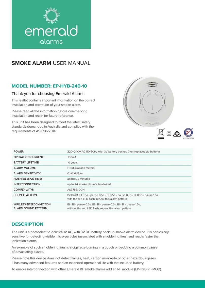
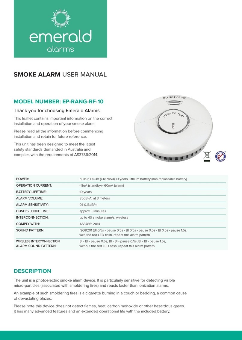
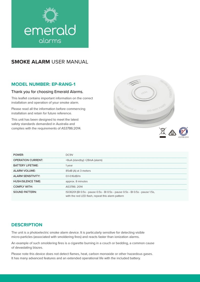
emerald alarms EP-VC-240-10 User manual

DESCRIPTION
The unit is a photoelectric 220~240V, AC 9V DC battery back-up smoke alarm device. It is particularly
sensitive for detecting visible micro-particles (associated with smoldering fires) and reacts faster than
ionization alarms.
An example of such smoldering fires is a cigarette burning in a couch or bedding a common cause
of devastating blazes.
Please note this device does not detect flames, heat, carbon monoxide or other hazardous gases.
It has many advanced features and an extended operational life with the included battery.
To enable interconnection with other Emerald RF smoke alarms add an RF module (EP-VC-RF-MOD).
MODEL NUMBER: EP-VC-240-10
Thank you for choosing Emerald Alarms.
This leaflet contains important information on the correct
installation and operation of your smoke alarm.
Please read all the information before commencing
installation and retain for future reference.
This unit has been designed to meet the latest safety
standards demanded in Australia and complies with the
requirements of AS3786:2014.
POWER: 220~240V AC 50-60Hz 10 years Lithium battery
backup
OPERATION CURRENT: <100mA
BATTERY LIFETIME: 10 years
ALARM VOLUME: >85dB (A) at 3 meters
ALARM SENSITIVITY: 0.1-0.16dB/m
HUSH/SILENCE TIME: approx. 8 minutes
INTERCONNECTION: up to 40 smoke alarm/s, hardwired
COMPLY WITH: AS3786: 2014
SOUND PATTERN: ISO8201 (Bl 0.5s - pause 0.5s - Bl 0.5s - pause 0.5s - Bl 0.5s - pause 1.5s,
with the red LED flash, repeat this alarm pattern
WIRELESS INTERCONNECTION
Bl - Bl - pause 0.5s, Bl - Bl - pause 0.5s, Bl - Bl - pause 1.5s,
ALARM SOUND PATTERN: without the red LED flash, repeat this alarm pattern
SMOKE ALARM USER MANUAL

ASSEMBLY
Failure to follow these instructions may result in injury and
equipment damage/malfunction.
1. Smoke alarm/s must be installed by a licensed electrician.
2. All interconnected smoke alarms must be supplied from the
same circuit.
3 A common neutral must be used for the interconnect to operate.
4. DO NOT connect the interconnect wire to active or neutral.
5. A maximum of 40 smoke alarms can be installed on one
circuit (wired interconnection only).
6. Alarm will not attach to mounting bracket unless battery is installed
correctly.
Warning: This smoke alarm is not suitable for wall (vertical)
mounting.
LOCATION OF SMOKE ALARMS
For maximum protection smoke alarms should be installed in
every room (except areas described in the previous section
‘Locations to Avoid’) to ensure people in the home will be able to hear
and respond to the alarm. At the very least install one smoke alarm on
every floor.
If you suspect a household member may not hear this smoke alarm
i.e. outdoor or indoor noise, sound sleepers, drug or alcohol usage,
the hard of hearing, etc install and maintain a specialty smoke alarm
device.
NOTE: In Australia each state has a dierent legislation when it comes
to smoke alarms. Please visit the relevant authority in your state for
specific legislation requirements.
LOCATIONS TO AVOID
1. Don’t place alarms in bathrooms, kitchens, garages or
other rooms where the alarm may be triggered by steam,
condensation and normal smoke/heat from appliances.
2. In areas with high humidity, like bathrooms or areas near
dishwashers or washing machines, install at least 3m away from
these areas.
3. Near air returns or heating and cooling supply vents, install
at least 1m away from these areas. The air could blow smoke away
from the detector, interrupting its alarm.
4. In rooms where the temperature may fall below 0°C or rise above
40°C (due to nuisance/false alarm activation).
5. In extremely dusty, dirty, or insect infested areas where
particles may interfere/obstruct with Alarm operation.
6. Away from air conditioning or ventilation grilles/louvers.
TYPICAL MULTISTORY OR SPLIT LEVEL HOME
For maximum protection, a smoke alarm should be installed on the
ceiling of each bedroom, living area, and hallway. Where a hallway
is more than 10 meters long install a smoke alarm at each end. Also
install a smoke alarm above each staircase.
For minimum protection, a smoke alarm should be installed above
each staircase, including the basement.
POSITION OF SMOKE ALARMS
Smoke will spread horizontally after rising to the ceiling, so it’s
advisable to install the smoke alarm in the centre of the ceiling where
possible. Avoid areas where there is no circulation.
• When mounting an alarm on the ceiling, locate it a minimum of
30cm from the side wall.
• Install smoke alarm/s on slopped, peaked or cathedral ceilings
between 50cm and 250cm from the highest point of the ceiling.
TYPICAL SINGLESTORY HOME
For maximum protection, a smoke alarm should be installed on the
ceiling of each bedroom, living area, and hallway. Where a hallway is
more than 10 meters long install a smoke alarm at each end. If there
is a basement install a smoke alarm on the basement ceiling at the
bottom of the stairwell.
Additionally, a smoke alarm should be installed in the hallway
between the living areas (incl. kitchen) and bedrooms. Place it as near
to the living areas as possible and ensure the smoke alarm is audible
when bedrooms are occupied.
LIVING ROOM
BATH
KITCHEN
BEDROOM
BEDROOM
BEDROOM BEDROOM
FAMILY ROOM
BEDROOM BEDROOM
KITCHEN
DINING
ROOM
LIVING
ROOM
BATH
Smoke alarm
for minimum protection
oSmoke alarm
for additional protection
Smoke alarm
for minimum protection
oSmoke alarm
for additional protection
Screw
Smoke Alarm
Ceiling
Install Bracket
Install hole

INTERCONNECTING SMOKE ALARMS
This smoke alarm oers a wired interconnection function.
Interconnecting smoke alarms can be linked together so that if one
alarm is activated all alarms linked on the circuit also sound.
NOTE: A 9V signal is applied to all interconnected wired smoke alarms.
The maximum wiring length is 150m between smoke alarms.
INTERCONNECTION WIRING DIAGRAM
(A) Active (E) Earth Loop (N) Neutral (I) Interconnect
WIRE CONNECTION
1. Strip the active, neutral and interconnect (if used) wires back to the
strip length.
2. Connect the wires to the correct terminals on the base and ensure
terminal screws are fully tightened. Check all wires are secure and
not cross connected to either active or neutral terminations.
Ensure the terminal cover is closed to avoid contact with the active
terminal.
3. Screw the mounting base onto the ceiling using the supplied
fittings.
4. Clip the smoke alarm onto the base.
NOTE: The smoke alarm base will only close if a battery is
installed. Do not attempt to close without a battery installed.
5. Turn on the mains power and check the smoke alarm’s green and red
LED. Green LED should illuminate to indicate mains power is present.
Red LED will pulse every 40 seconds indicating correct operation
of the battery back up.
6. Press the Test/Hush button to check the smoke alarm is working.
Warning: Installation is not complete until both LEDs are
functioning correctly and the alarm has been checked for
correct operation. Wiring must be installed in compliance
with local regulations.
Use a minimum of 1.0mm2 250V insulated wire for all wiring, including
interconnecting wiring.
Terminal Provisions: active, neutral, loop and interconnect terminals,
each accommodates 2x1.5mm2.
OPERATION AND TESTING
Smoke alarms are an important safety device in the home. It is import-
ant to check them regularly to ensure they are operating correctly.
Regular Mode
When there is no smoke present the green LED light remains on and
the red LED should flash every 40 seconds to show the alarm is active.
Alarm Mode
When the alarm detects smoke, the red LED will flash once per
second and the alarm will sound loudly. The flashing LED and alarm will
continue until the air is cleared.
Fault Mode
The alarm will generate a ‘chirp’ every 48 seconds indicating a fault
or a low battery.
TESTING YOUR SMOKE ALARM
It is recommended that you test your smoke alarm once a week to
ensure the smoke alarm is working correctly. Test by pushing the
test button on the cover. The alarm will sound if the alarm, electronic
circuitry and battery are working. If no alarm sounds, the smoke alarm
has a defective battery, or another fault.
Warning: Do not use an open flame to test your alarm. You
could damage the alarm or ignite combustible materials and
start a structure fire.
LOW BATTERY POWER
Should your smoke alarm have a low battery the unit will emit an
audible ‘chirp’ once every 48 seconds and the red LED light flashes
once at the same time. When this occurs you must replace the battery
immediately. Your smoke alarm will continue to warn of this low battery
for at least 30 days. However, failure to change the battery after this
time would mean your smoke alarm may have insucient power to
alert you in a real fire situation.
Warning: Your smoke alarm requires the battery to have
sucient capacity of power to operate correctly.
SILENCE ALARM
If your smoke alarm emits the full alarm signal and you are not
testing the unit, the smoke alarm is warning you of a potentially
dangerous situation that requires your immediate attention. Only use
the alarm silence function after making sure that there is no ongoing
fire emergency situation.
Do not block the vents on the alarm or disable the smoke alarm in any
way as this will remove your protection.
Smoke alarms can sometimes react to cooking fumes or other non
emergency situations. In the event of a known false alarm your smoke
alarm can be temporarily silenced by pressing the test button. Your
alarm will automatically return to full sensitivity within 8 minutes.
1. Press and release the silence button, the alarm sound will stop.
2. Your alarm will silence and enter into a reduced sensitivity
reset cycle for approximately 8 minutes.
3. During the reduced sensitivity reset cycle, the red LED will flash
every 8 seconds indicating it is running in silent mode.
4. Your alarm will automatically return to full sensitivity on
completion of the reset cycle and the red LED will revert to flashing
once every 48 seconds.
Warning: Never ignore any alarm. Ignoring the alarm may result
in injury or death. If your smoke alarm activates and you are not
absolutely certain of the source of the smoke, get everyone out
of the house immediately.

WARRANTY INFORMATION
Emerald Alarms Pty Ltd warrants this smoke alarm to the original purchaser.
Emerald Alarms Pty Ltd warrants each new smoke alarm is free from defects in material and workmanship under normal use
and service for a period of 7 years from the date of purchase.
This warranty does not cover damage resulting from accident, misuse or abuse or lack of reasonable care of the product.
In no case shall Emerald Alarms Pty Ltd be liable for any incidental or consequential damages for breach of this or any other
warranty express or implied whatsoever. Faulty product can be mailed to the following address with a detailed explanation
of problem.
Emerald Alarms Pty Ltd
ABN 50 632 601 453
2/29 Mitchell Rd Brookvale NSW 2100
BATTERY REPLACEMENT
The secondary backup power for the smoke alarm is supplied
by a 9V lithium battery.
The battery should last at least 10 years under normal operating
conditions (without wireless interconnection).
Warning:
Test the smoke alarm for correct operation using the test facility
whenever the battery is replaced.
Recommended battery replacement -
Lithium Battery: EVE CR9V / P.
Insert the battery ensuring the positive and negative terminals
on the battery and the smoke alarm match, then press the other
side into the slot.
2021.10
ROUTINE MAINTENANCE
Like other electrical accessories in the home, smoke alarms
require maintenance to ensure ecient and eective operation.
Proper maintenance can also reduce the likelihood of false alarms.
Warning: Electrical shock hazard. Disconnect the AC mains at
the fuse box or circuit breaker powering the alarm before
following the cleaning instructions.
1. In addition to weekly testing, the alarm requires cleaning at least
once a month to remove dust, dirt, or debris.
2. Using a vacuum cleaner with the soft brush vacuum all sides and
cover of smoke alarm device.
NOTE: Do not attempt to remove the cover to clean inside. This will
aect warranty.
Warning:
1. Photoelectric smoke detectors can reduce the likelihood of a
disaster, but they cannot guarantee a 100% safety.
2. To ensure your maximum security, please install all smoke
detectors exactly according to this manual.
3. Keep the detectors clean. Do not allow dust to accumulate
and test them at least once a week.
4. If they are not working properly replace them immediately.
Other emerald alarms Smoke Alarm manuals
Popular Smoke Alarm manuals by other brands
VESDA
VESDA lasercompact VLC-500 product manual

Honeywell
Honeywell GENT Venturi-Air Duct Kit Installation instruction
CALECTRO
CALECTRO Uniguard Superflow UG-3-O Installation instruction
Abus
Abus FURM50000 Installation and operating instructions
DM TECH
DM TECH D9000 MCP Instructions for installation and operation

Abus
Abus GRWM30500 user manual
