Emerald EE-HWS-A1-220-2 User manual

ALL-IN-ONE HEAT PUMP WATER HEATER
USER MANUAL
MODEL NUMBERS:
Residential:
EE-HWS-A1-220 EE-HWS-A1-220E
EE-HWS-A1-270 EE-HWS-A1-270E
Commercial:
EE-HWS-A1-220-1/-2 EE-HWS-A1-220E-1/-2
EE-HWS-A1-270-1/-2 EE-HWS-A1-270E-1/-2
Thank you for choosing Emerald Energy.
This leaflet contains important information on the correct
installation and operation of your heat pump water heater.
Read these instructions carefully before installation.
Keep this manual in a handy for future reference.
IMPORTANT NOTICE
Please read this manual carefully before you attempt
to install this product. Failure to do so may result in
the product not working according to its design.
CONTENTS
SAFETY PRECAUTIONS 2
GENERAL INFORMATION 3
PART NAMES 4
INSTALLATION 5
PLUMBING CONNECTION 7
ELECTRICAL CONNECTION 10
CONTROLLER INSTRUCTIONS 12
COMMISSIONING THE SYSTEM 17
OPERATION AND MAINTENANCE 19
AFTER SALES SERVICE 20

INSTALLATION & OPERATION
• This appliance uses R290 (propane) refrigerant, which is a
flammable gas class 3 according to AS 1677. Servicing of
components which use the refrigerant, such as the compressor,
must be and must be handled by a refrigeration mechanic with
appropriate Australian refrigerant handling license.
• WARNING Risk of fire/flammable material. If the refrigerant is
leaked, together with an external ignition source, there is a
possibility of ignition.
• DO NOT store chemicals or flammable materials near this
appliance.
• NEVER use a flammable spray such as hair spray, paint, etc near
this unit as this may cause a fire.
• The appliance should not be stored or transported in an area with
an ignition source (e.g. open flame).
• Do no pierce or burn the appliance.
• Be aware that the refrigerant may not cause an odour.
• Compliance with AS/NZS 5601 must be observed while storing
the appliance.
• National and state regulations exist for the storage, transportation
and handling of hazardous goods including flammable gasses.
The maximum number of and configuration of the equipment
permitted to be transported or stored together will be determined
by the appliance regulations.
⚠ WARNING
• Risk of fire/flammable material. If the refrigerant is leaking, switch
o the unit at the mains and contact the service agent.
• DO NOT store chemicals or flammable materials near this
appliance.
• NEVER use a flammable spray such as hair spray, paint, etc near
this unit as it may cause fire.
• Avoid risk of injury from contact with refrigerant if you notice a
leak.
• If you suspect the refrigerant is leaking then Do not smoke or
operate electrical equipment.
• End of life recycling: The refrigerant must not enter the
atmosphere. Only have the refrigerant removed by qualified
professional.
If the hot water system is not used for two weeks or more,
a quantity of highly flammable hydrogen gas may accumulate
in the water heater. To dissipate this gas safely, it is recom-
mended that a hot tap be turned on for several minutes or until
discharge of gas ceases. Use a sink, basin, or bath outlet, but
not a dishwasher, clothes washer, or other appliance. During
this procedure, there must be no smoking, open flame, or any
electrical appliance operating nearby. If hydrogen is discharged
through the tap, it will probably make an unusual sound as with
air escaping.
SAFETY PRECAUTIONS
⚠ INSTALLATION & OPERATION
• The installation must comply with the AS/NZS 5149 Standards.
• DO NOT install or operate this system before reading the
manufacturer’s instructions.
• This appliance must be installed, commissioned and serviced by
an authorized person in accordance with all applicable local rules
and regulations.
•
Removing access covers and or water heating system components
will expose 240V wiring and MUST only be removed by an
authorised person.
• If the systems power supply is damaged, it MUST BE replaced by
an authorised person in order to avoid a hazard. Take care not to
touch the power connections or plugs with wet hands.
• This appliance is not intended for use by persons (including
children) with reduced physical, sensory or mental capabilities, or
lack of experience and knowledge, unless they have been given
supervision or instruction concerning use of the appliance by a
person responsible for their safety. Children should be supervised
to ensure they DO NOT play with the appliance.
• For continued safety of this appliance it must be installed,
operated and maintained in accordance with the manufacturer’s
instructions.
• Care should be taken not to touch the pipe work as it may be
HOT!
• DO NOT place articles on or against this appliance.
• DO NOT store chemicals or flammable materials near this
appliance.
• DO NOT operate with collectors or covers removed from this
appliance.
• DO NOT activate heat pump unless cylinder is full of water.
• Household electrics must have a reliable earth connection.
• This product must be protected with a residual current device
of adequate rating.
• Do not interfere with any permanent instruction, labels or warning
plate attached to the external cover of this heat pump.
• This product must be installed by qualified person in the
mechanical and electrical industry.
• Always comply with local wiring regulations.
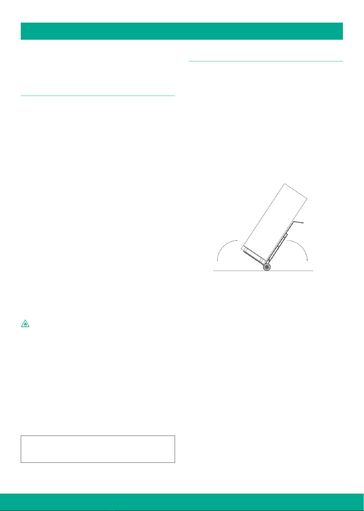
• Always engage with a trained professional to relocate this
product after it has been professionally installed.
• Maintenance and repair work must only be undertaken by
trained and qualified personnel.
• The electrical connection to this product must be via a 20A RCD/
MCB or RCBO with a test button function.
• This appliance should never be used by children.
• Do not operate this heat pump in a wet room such as a bathroom
or unless it is housed in a separate cupboard within that room.
2

GENERAL INFORMATION
MEASUREMENT
MODEL WEIGHT
(kg)
DIMENSION
(mm) POWER SUPPLY
EE-HWS-A1-220(-1) 118 600×1598 220V-240V/ 50Hz
EE-HWS-A1-220E(-1) 118 600×1598 220V-240V/ 50Hz
EE-HWS-A1-270(-1) 136 600×1826 220V-240V/ 50Hz
EE-HWS-A1-270E(-1) 136 600×1826 220V-240V/ 50Hz
3
EE-HWS-A1-220E(-1)
(The electric heating element is not included in EE-HWS-A1-220)
EE-HWS-A1-270E(-1)
(The electric heating element is not included in EE-HWS-A1-270)
Power cable hole Display
Thermal sensor
Electric heating element
Magnesium anode
Condensate drainage hole
TPR safety valve
Hot water outlet
Cold water inlet
102 836 151
1598
Power cable hole
Thermal sensor
Electric heating element
Magnesium anode
Condensate drainage port
TPR safety valve
Hot water outlet
Cold water inlet
151
1826
1064
102
Display

GENERAL INFORMATION
4
EXPLODED DRAWING
No. DESCRIPTION QTY REMARK
1 Feet 4 PP
2 Bottom tray 1 Galvanized plate
3 Position block 4 PP
4 Outer casing 1 Galvanized plate
5 Hand grip 2 ABS
6 Electric heater cover 1 Galvanized plate
7 Decorative rubber ring 4 ABS
8 Enamel tank 1
9 Microchannel heat exchanger 1 Aluminium alloy
10 Electric heater 1
11 Microchannel outlet 1 TP2M
12 Microchannel inlet 1 TP2M
13 Bottom bracket 1 Galvanized plate
14 Curve adapter 1 PVC
15 Condensate drainage port 1 PVC
16 Condensate tray 1 ABS
17 Self tapping screw 8
18 Top lid 1 Galvanized plate
19 Power cable screw 1 PP
20 Controller cover 1 PVC
21 Controller 1
22 Electric box cover 1 Galvanized plate
23 Terminal block 1
24 Main board 1
25 Relay 1
26 Electric box 1 Galvanized plate
27 Electric box bracket 1 Galvanized plate
28 Evaporator bracket 2 Galvanized plate
29 Top unit tray 1 Galvanized plate
30 Evaporator 1
31 Fan motor bracket 1 Galvanized plate
32 Fan motor 1
33 Fan blade 1 ASG20
34 Fan box 1
35 Fan box cover 1
36 EEV 1
37 Transition pipe 1 TP2M
38 Compressor 1
39 4 way valve 1
*The electric heating element is not included in EE-HWS-A1-220(-1) & EE-HWS-A1-270(-1)

Pallet for
transportation
only
Do not tilt
beyond 30º
INSTALLATION
5
All Emerald Energy heat pumps are designed for installation by a
licensed plumber in accordance with standards set out in AS/NZS
3500.2 “National Plumbing and Drainage Code Hot Water Supply
Systems - Acceptable Solutions”.
CHOOSE A SUITABLE LOCATION
1. Ideally the Heat Pump should be installed outdoors.
For indoor installations the ensure that the location complies
with the requirements of AS/NZS 5149.
2. Please ensure there is adequate space for installation and
maintenance. It is recommended a head height of 300mm is
required.
3. The product is to be installed in a dry and free from humidity
location.
4. Support surface must be flat (horizontal angle must not be more
than 2°), and can hold the products weight when filled with water.
Please refer to the technical data sheet for the products weight.
5. Please select a suitable location for the exhaust air vent to
the outside. Always insulate the exhaust air ducting to avoid
condensation when operational.
6. Please ensure there is access to the removal front panel for
maintenance.
7. Always allow extra room for pipe connections and power cables.
8. Always refrain from installing on a surface with loose coverings
as the product may make a vibrating noise when operating.
9. The areas containing toxic gases or mineral oils are not
recommended as suitable installation locations of the product.
10. Coastal Installation – Installations within 500m of a coastline may
require additional maintenance. Proximity to the coast without
adequate shelter, can reduce the lifespan of the system and
could risk the system warranty.
The Emerald integrated series uses a flammable gas, therefore:
• The appliance should not be stored or transported in an area with
an ignition source
• Do no pierce or burn the appliance.
• Be aware that the refrigerant may not cause an odour.
• Compliance with AS/NZS 5601 must be observed while storing
the appliance.
National and state regulations exist for the storage, transportation
and handling of hazardous goods including flammable gasses.
The maximum number of and configuration of the equipment
permitted to be transported or stored together will be determined
by the appliance regulations.
⚠If the product is installed in a location where there is a
possibility of frost, then all precautions must be taken to
ensure all pipework is suciently insulated.
TRANSPORTING THE HEAT PUMP
1. Emerald Energy heat pumps must be stored and transported in
a near vertical position at all times with a tilt ratio of no more than
30°. Transporting or storing the unit in a horizontal position will
void warranty.
2. The system should always be transported in it's packaging.
3. The weight of the package system is 138KG (EE-HWS-A1-220 &
EE-HWS-A1-220E) and 156KG ( EE-HWS-A1-270 & EE-HWS-A1-
270E). The system must be handled by two people at all times
to avoid unnecessary strain and damaged.
4. Please note the outer casing of the unit is susceptible to
denting and damage. Care and consideration should be taken
into account when moving the unit as any marks caused by
inappropriate handling are not deemed as defects and are not
covered under warranty.

INSTALLATION
6
INSTALLATION OF THE HEAT PUMP
1. BASE
• The unit should be installed on a concrete plinth or stable structure
capable of sustaining weights in excess of 400kg. The supporting
structure must not shift over time (due to water drainage etc.).
A concrete base of at least 50mm thick or a well-seasoned
hardwood slat at least 25mm is required. If a concrete base paver
is being used, a minimum dimension of 600mm x 600mm is
required.
• Please ensure that all four feet are supported by the base being
used otherwise warranties may be voided.
• Proper drainage should be observed for any overflow.
• When installed the unit must be completely vertical and level as
to ensure that condensate can be properly drained. If the system
is installed at a level with a tilt of more than 3 degrees, warranties
may be voided.
• If property damage can occur due to water leakage, a safe tray
(overflow tray) must be installed.
2. AIR FLOW
• Avoid installation in areas where falling debris such as leaves is
prevalent as this may result in air vents being blocked or the unit
being damaged.
• Avoid placing the system in locations with multiple walls or
structures (Diagram 1 & 2).
• Always maintain optimum perimeter from all structures
• If installed under fixtures or home eves, there must be a minimum
300mm clearance between the top of the unit, 600mm on the
right hand side of the system (when facing unit) and 150mm on
the left hand side of the system (when facing system) (see section
2.3 AIR FLOW). The unit must be installed a minimum of 150mm
o your home's wall so that the entire unit can be accessed
during any servicing work as well as to prevent circulation of
cold air (see section 2.3 AIR FLOW). If the system cannot be
properly serviced due to the system being installed outside of
these specifications, the owner will be liable for the associated
plumbing costs of draining and moving the system.
•
The unit should be installed so that the control interface is accessible
to users and that there is clear access to the electrical panel at
the back of the system. Where incorrect installation has occurred
warranties may be void or additional charges may be required to
ensure that the system is compliant.
⚠ WARNING
• A minimum of 20m3of unobstructed space surrounding the unit.
• For indoor installations the ensure that the location complies with
the requirements of AS/NZS 5149.
• The electrical access point and display panel should always be
accessible.
VENTILATION GUIDELINES:
These are the ventilation guidelines for the Heat Pump to operate
correctly and do not relate to the storage of flammable refrigerants.
Ensure that the location complies with the requirements of AS/NZS
5149.
The Heat Pump should ideally be installed outdoors. For indoor
installations, below explains the possible issues and preventive
measures that should be taken.
The issue with indoor installations is the risk of air recirculation, the
temperature of air in the confined space will gradually reduce until the
Heat Pump loses eciency and possibly until failure.
The ambient air temperature should not drop below 5°C. The air
temperature should be monitored in the space to ensure enough
ventilation over the lifetime of the Heat Pump.
The following recommendations help to prevent a drop in air
temperature:
• Indoor areas with an air volume greater than 53m are suitable
for indoor installations
• Areas smaller than 53m require cross ventilation.
Cross ventilation can be achieved naturally or mechanically
• Natural ventilation is achieved if there are suitably sized openings
on opposite ends of the enclosure providing cross ventilation
• If mechanical ventilation is provided via a supply or extract fan,
then the minimum volume of air required is 1000 m/h (278 L/s)
• For mechanically ventilated areas, a make-up air path is required.
This can be in the form of grilles, undercut doors, open doors,
open windows etc
• To achieve cross ventilation the location of the make-up air path
should be on the opposite side of the enclosure to the fan
fan exhaust
300mm
600mm
150mm

PLUMBING CONNECTIONS
7
PLUMBING CONNECTIONS
COLD WATER SUPPLY OUTLET
• The cold water supply connection is a G 3/4” female thread.
• The cold water supply should be connected to G 3/4” socket.
• The cold water supply outlet can also act as a drainage point for
emptying the system.
HOT WATER CONNECTION
• The hot water supply connection is a G 3/4” female thread.
• The hot water supply should be connected to G 3/4” socket.
• To ensure thermal eciency all hot water lines and connections
must be insulated with a minimum 13mm closed cell insulation.
• All hot water supply parts must be constructed from copper.
CONDENSATE DRAIN
• The process of heat extraction from the atmosphere through
evaporator coils results in the production of water in the form
of condensation. More humid environments will produce higher
rates of condensation.
• To collect this water by-product a Condensate Tray is located at
the bottom of the heat pump. Overflow from this tray runs out
through the Condensate Drain.
• The system comes with a pre-installed condensate drain
connection elbow. Drainage of condensate from elbow to
nearest storm water to be done by the collection of condensate
into the drainage pipe. If not drained properly, the condensate
line will attract termites as well produce algae and moss growth.
• The Condensate line should be free of kinks and as the water is
gravity fed, should only be running down to ensure the free flow
of water.
PRESSURE & TEMPERATURE RELIEF TPR VALVE
• The system is supplied with a loose TPR valve appropriate to the
pressure rating of the water heater tank. If the TPR valve is not
present please contact your supplier. The valve Rated capacity:
850kPa;10kW; Set temperature: 93-99°C.
• The supplied TPR valve must be installed at Point 4 in section 3.2
DYNAMIC X8 Connection Dimensions and Components under
the socket marked "RELIEF VALVE".
• The TPR valve must be insulated with a minimum 13mm closed
coupled insulation, to minimize heat lost.
• The relief valve must be installed so that the drain line is facing
downwards at all times with the discharge point remaining open
to the atmosphere.
• A discharge pipe connected to the pressure relief device is to be
installed in a continuously downward direction and in a frost-free
environment. Do not connect any pressure-relief device to the
condensate drain pipe. The water may drip from the discharge
pipe of the pressure-relief device. This pipe must be left open to
the atmosphere. The pressure-relief device is to be operated
regularly to remove lime deposits and to verify that it is not
blocked.
1 Cold water supply outlet (G 3/4" female thread)
2 Hot water outlet (G 3/4" female thread)
3 Condensing drainage Elbow*
4 P&T Relief Valve* (G 1/2" female) (850k Pa_
5 Electrical cable
6 Tempering valve (high performance recommended)
7 Expansion control valve (ECV)
8 Pressure reduction valve (500k Pa)
9 Non-return/Isolation valve
10 Isolation switch (hardwired into 10 amp circuit)
* Supplied with system

PLUMBING CONNECTIONS
8
OPERATING THE TPR VALVE
FREQUENCY: EVERY HALF YEAR REPLACE IF REQUIRED
It is recommended to operate the TPR valve periodically to ensure
water flows freely. If water doesn't flow freely, the TPR valve will need
to be replaced.
• Locate the TPR valve on the left hand side of the unit.
• Carefully release the valve using the lever & release some water
from the tank.
NOTE: Water expelled may be extremely hot.
• If water flows freely the TPR appears to still be in a suitable
working condition.
• If water does not flow freely it would appear the TPR valve is due
for replacement.
• If the TPR valve needs replacing, please contact your plumber or
our service team for further assistance.
TEMPERING VALVE
• The systems are automatically programmed to produce hot water
in excess of 50°C. As such, in accordance with AS/NZS3500, it is
mandatory that a Tempering Valve is installed.
• We recommend a high performance or solar rated tempering
valve is used to ensure a more accurate hot water delivery
temperature.
• Your old hot water system might not have had a tempering valve
installed before and therefore you will notice a change in the
temperature of the hot water. This is normal and required under
new legislation. Should you have any concerns, please contact
your installer.
EXPANSION CONTROL VALVE
• Please observe local requirements with regards to the installation
of an ECV (optional in most councils).
• When installing an ECV, ensure that the connecting pipe diameter
no greater than that of the safety valve.
•
Ensure the drain is sized to allow for water runo, even in incidents
where the safety valve has been fully opened.
• The drain outlet must always remain open to the atmosphere and
must not have a closing function.
• The ECV should be rated at no more than 700kPa.
PRESSURE REDUCING VALVE
• This water heater is supplied with a TPR valve rated at 850kPa
and is designed for direct connection to mains water supply with
a pressure not exceeding this rating.
• Should main pressure fluctuate above this rating, a pressure
limiting device (AS1357) should be connected at Connection
Dimensions and Components.
NONRETURN/ISOLATING VALVE
• It is compulsory that a non-returning/isolation valve is installed
directly into the cold-water supply line feeding the system. This
will allow the hot water system to be isolated from the rest of the
homes water supply, making servicing, draining, and replacing the
unit easy. A hose-set must not be used to connect the system to
water supply.
• The non-return/isolation valve can be combined with a TPR valve
to form a duo valve.
ALLOWABLE MINMAX FILLING WATER PRESSURE
Allowable min-max filling water pressure: Min 200KPA - Max 750KPA
THE DEMANDED QUALITY OF WATER
• The bad quality water will produce more scale and sand, so this
kind of water should be filtered.
• The water quality should be analyzed before system running, to
measure the PH value, conductivity, Chloride ion concentration
and sulphate ion concentration.
• The acceptable water quality standard is showed as below table.
PH
value
Total
hardness Conductivity Sulphate
ion
Chlorine
ion
Ammonia
ion
7~8.5 < 50ppm <200V/cm(25ºC) None < 50ppm None
Sulfate ion Silicon Iron content Sodium Ca
< 50ppm < 50ppm < 0.3ppm No requirement < 50ppm
• Suggest the filter meshes is about 40 meshes.
CHECKING THE ANODE & REPLACING IF REQUIRED
(Frequency: Every Half Year - Replace if required)
The anode protects the inner lining of your hot water tank. When
the anode become degraded the level of protection is diminished.
It is recommended that anode is periodically checked for its level of
degradation and gets replaced if required.
• Turn o the power and turn o the cold water inlet valve.
• Open a hot water tap and decrease the pressure of the inner
container.
• Locate the anode position.
• Remove the anode cover by releasing the two screws.
• Unscrew the anode.
• Check for degradation.
• If still in suitable condition, refit ensuring an eective seal.
• If anode is in an unsuitable condition, replace with a new one.
Failing to replace the anode when required will result in a loss of
warranty for the water tank.
• Reopen the cold water inlet valve.
• Open a hot water tap until hot water flows out, then turn o the
hot water tap.
• Turn on the power to restart the unit.
• Now the unit can be used as normal.

PLUMBING CONNECTIONS
9
CLEANING THE INNER TANK AND ELECTRIC HEATING ELEMENT
FREQUENCY: EVERY HALF YEAR
It is recommended to clean the inner tank and electric heating
element regularly to maintain ecient performance.
• Turn o the power.
• Close the cold water inlet valve & open a hot water tap.
• Use a flexible pipe to connect the drain port to a suitable sewage
drain. (Note: The min. heat resistance of the drain pipe must not
be less than 93°, if the drain pipe does not meet the requirement,
please open the cold water inlet valve & open a hot water tap,
until the temperature of the water is suitable for the drain pipe).
• Open the drain port of the water heater; drain out all the water
in the inner tank. If it is needed, use water to wash the inner tank
several times to clear the deposits.
• Close the drain port, re-fill the inner tank with water, and turn the
power back on.
⚠ FILLING THE SYSTEM:
• Once the system has been connected in accordance to Section
3.0 and 4.0 of this handbook, the tank can be filled and pressurised.
• Open the non-return valve on the cold-water inlet to begin filling
the system with water. At the same time, ensure at least one hot
water tap is open inside the property. While the system begins
filling with water you will hear air being expelled from the open
hot water tap. This is called "bleeding the system" and it ensures
that no air pockets remain. Once water begins running out of the
hot water tap, the system is completely bled, and you can then
turn the tap o.
• Always ensure the tank is completely full before connecting and
turning on the electricity supply.

ELECTRICAL CONNECTIONS
10
⚠WARNING
• The electrical connections must be completed by a qualified
and trained professional.
• The circuit must be connected to a reliable earth electrode
connected to the consumer unit.
• The testing of the circuit and final connections are the
responsibility of the trained installer.
PRECONNECTION & REGULATIONS
• When connecting the unit, electrical work must comply with the
local supply authority regulations as well as AS3000.
• The power rating of the unit is set at 10 amps as such the mains
power supplying the unit must have a 10 amp minimum circuit
breaker fitted.
• Note this device is fitted with an over-temperature control cut-out.
Under no circumstances must the water heater be in operation
without this safety device connected to the circuit. Re-setting and
replacement of this device must only be carried out by a qualified
electrical contractor.
•
(AS/NZS 60335-1 Clause 7.12.2): disconnection must be incorporated
in the fixed wiring in accordance with the wiring rules.
• FUSE: 260V, 16A
• Unit power supply circuit must be ground, power supply wire and
external grounding reliable connection, and the external grounding
is eective.
• Wiring must be constructed by the professional installation
technicians in accordance with the circuit diagram.
• Power line and signal line layout should be neat, reasonable,
can not interfere with each other, but not with the connecting
pipe and the valve body contact.
• The unit is not matching the power line, please supply
specifications refer to provisions, does not allow the wires
connecting.
• After all wiring construction is completed, please carefully check
it before switch on the power supply.
• If the supply cord is damaged, it must be replaced by either the
manufacturer, a service agent or similarly qualified person to
avoid a hazard.

ELECTRICAL CONNECTIONS
11
WIRING DIAGRAM
EE-HWS-A1-220(-1) & EE-HWS-A1-270(-1)
EE-HWS-A1-220E(-1) & EE-HWS-A1-270E(-1)
V G A B
T4 T6
T1 T2 T3 T5
B
A
U
V
W
PE
AC-N
AC-L
HPS
EXV1
D03
D06
D07
RD
RD
4WV
5
EXV
T1 T2 T3 T5 T4
HPS
4
Controller
U
V
W
Y/GN
N
L
XT1
240V/~ /50Hz
Power In
WH
WH
RD
BU
COMP
U
V
W
MF
5
COMP Compressor
MF Motor Fan
4WV 4 way valve
EXV Electronic Expansion Valve
Coil temperature sensor
Exhaust temperature sensor
HPS High pressure switch
Suction temperature sensor
Ambient temperature sensor
BU
BR
GN
BLUE
BROWN
GREEN
YYELLOW
WIRE COLOR CODE
WH
RD
BK
WHITE
RED
BLACK
OR ORANGE
Inlet temperature sensor
T1
T2
T3
T5
T4
AP1
BU
RD
BU
32190001000666
Y/GN
Y/GN
BU
OP
BU
RD
RD
BU
WH
15V
GND
310V
VSP
FG
BK
WH
XT1 Termianl
AP1 Control panel
KA1 Relay
OP Overheat protector
AC-L
AC-N
CN1
CN2
AP2
The power live
pass e d through
the magnetic ring
4
AP2 Power Detection Module
BU
RD
AP1.D09
1 2
ON
3 4
D09
V G A B
T4 T6
T1 T2 T3 T5
B
A
PE
AC-N
AC-L
HPS
EXV1
D03
D06
D07
RD
RD
12
ON
34
4WV
5
EXV
T1 T2 T3 T5 T4
HPS 4
Controller
U
V
W
Y/GN
N
L
XT1
240V/~ /50Hz
Power In
WH
MF 5
COMP Compressor
MF Motor Fan
4WV 4 way valve
EXV Electronic Expansion Valve
Coil temperature sensor
Exhaust temperature sensor
HPS High pressure switch
Suction temperature sensor
Ambient temperature sensor
BU
BR
GN
BLUE
BROWN
GREEN
YYELLOW
WIRE COLOR CODE
WH
RD
BK
WHITE
RED
BLACK
OR ORANGE
Inlet temperature sensor
T1
T2
T3
T5
T4
BR BU
BU
RD
Y/GN
AP1
E-heater
BU
RD RD
BU
RD
BU
32190001000657
Y/GN
BU
KA1
NO COM
BU
RD
15V
GND
310V
VSP
FG
BK
WH
XT1.N
U
V
W
WH
RD
BU
COMPU
V
W
Y/GN
BU
OP
RD
BU
WH
AC-L
AC-N
CN1
CN2
AP2
The p o w e r l i v e
pass ed throug h
the m agne t i c r i ng
4AP1.D09
BU
RD
XT1 Termianl
AP1 Control panel
KA1 Relay
OP Overheat protector
AP2 Power Detection Module
D09

12
CONTROLLER INSTRUCTIONS
BUTTON INSTRUCTIONS
On/O
Button
• Press this button for 3 seconds to unlock the controller;
• Press this button for one second to turn ON/OFF system;
• In Query status, press this button to return to the main interface;
• In Setting status, press this button to return to the main interface
Running Mode When the system is turned on press this button to select dierent running mode;
Up & Down
• Press UP or DOWN button quickly at main interface to set target water temp.
• Press UP or DOWN button for 3 seconds to enter the query state.
• Under back end parameter setting status, press the UP or DOWN button to adjust setting value.
• Under Timer or Clock setting status, press the UP or DOWN button to adjust setting value
Clock & Timer
Setting
• In the main interface, press this button shortly to enter the real clock setting, and press this button again
shortly again to switch the real time setting area “hour” and “minute”.
• In the main interface, press this button for 3 seconds to enter/exit the timer period setting or mode.
• In the main interface, press this button for 3 seconds to enter/exit the timer period.
• Under timer setting status, press this button shortly to switch the timer setting area “hour” and “minute”.
• Under timer setting status, press this button for 3 seconds to cancel the timer setting.
• Under clock setting status, press this button to activate/deactivate weekly function
ICON INSTRUCTIONS
SYMBOL STATUS DESCRIPTION
Constantly Bright System is under standard mode
+Constantly Bright System is under silent mode
++ Constantly Bright System is under booster mode
Constantly Bright System is under defrost
Constantly Bright Service required
Constantly Bright Compressor is running
Constantly Bright Fan motor is running
Constantly Bright Electric heating element is on for heating (only for the models with element)
Flashing Electric heating element is on for sterilization (only for the models with element)
RT Constantly Bright Current water temperature in the tank
SET Constantly Bright Set target water temperature in the tank
Display Display actual water temperature, set water temperature, and fault code
º
C
Constantly Bright Currently showing Celsius temperature
Display Show clock time
Display Timer is on
ON Display Timer function is activated
OFF Display Timer function is deactivated
1Constantly Bright / Extinguished Timing period 1 set / Timer period 1 not set
2Constantly Bright / Extinguished Timing period 2 set / Timer period 2 not set
3Constantly bright / Extinguished Timing period 3 set / Timer period 3 not set
Constantly Bright The controller is locked
Constantly Bright The Wi-Fi is connected

13
CONTROLLER INSTRUCTIONS
OPERATION INSTRUCTIONS
CONTROLLER LOCK AND UNLOCK
1. In the locked state, press the button for 5 seconds, the buzzer
will beep once, then the controller is unlocked;
2. The controller gets locked automatically when no operation for
60 seconds;
SELECT RUNNING MODE
STANDARD MODE:
• Press the button to switch to Standard mode. Under this
mode, the icon lights up;
• The setting range is optional with 15ºC - 63ºC for target water
temperature;
• Heat pump would be running with the most ecient way;
• If the heat pump fails, the electric heating element would be
automatically activated, and the water would be heated up to the
target water temperature;
SILENT MODE:
• Press the button to switch to Booster mode. Under this mode,
the + + icons light up. The setting range is optional with
15ºC - 60ºC for target water temperature;
• Heat pump would be running with lower noise (lower running
frequency)
• If the heat pump fails, the electric heating element would be
automatically activated, and the water would be heated up to the
target water temperature.
• This is a one shot function and will return to standard mode after
one cycle.
3 BOOSTER MODE:
• Press the button to select Booster mode. Under this mode,
the + + icons light up.
• The setting range is optional with 15ºC - 70ºC for target water
temperature for the model EE-HWS-A1-220E(-1) and EE-HWS-A1-
270E(-1), and 15ºC - 60ºC for the model EE-HWS-A1-220(-1) and
EE-HWS-A1-270(-1);
• Heat pump would be running with bigger heating capacity (bigger
running frequency)
• If the target water temperature ≤60ºC, both the heat pump and
electric heating element work simultaneously during the entire
heating cycle;
• If the heat pump fails, only the electric heating element heats the
water up to the target water temperature.
• This is a one shot function and will return to standard mode after
one cycle.
WATER TANK TEMPERATURE SETTING
In the case of power on and unlocking, press the or button on
the main interface to adjust the water temperature setting value of
the water tank.
REAL TIME CLOCK SETTING
1. In the main interface, press the button shortly to enter the
real-time clock setting
2. In the real-time clock setting interface, press the key once,
and the number of the hour part will flash. At this time, press the
or button to set the hour of the real-time clock;
3. After setting the hour, press the button again, the number in
the minute part flashes, press the button at this time or ,
the minute of the real-time clock can be set;
4. After the minute part is set, press the button again to confirm
the current clock setting and return to the main interface;
5. In the real-time clock setting interface, if there is no operation for
60 seconds, confirm the current real-time clock setting value and
return to the main interface;
6. In the real-time clock setting interface, press the button to
confirm the current real-time clock setting value and return to the
main interface.
LEGIONELLA CONTROL
For legionella control our systems heat at least 45% of the water tank
to 60ºC daily. This sterilisation process will occur daily regardless of
any manual setting changes made to the controller.

14
CONTROLLER INSTRUCTIONS
OPERATION INSTRUCTIONS CONTINUED
TIMER SETTING
1. On the main interface, press the button for 3 seconds to enter
the setting interface of the timer periods;
2. At this time, press the or button to set the timing 1, 2, and 3
periods;
3. When the No. 1 segment is flashing regularly, press the button
to enter the setting interface of the hour part of the timing power-
on of the timing period 1. The number in the hour part of the
timing start time flashes, at this time press the or button,
you can set time;
4. After setting the hour part of the timed start-up, press the
button again, it represents the minutes of the timed start-up time
Part of the numbers flashes, at this time, press the or
button to set the minutes of the timing 1 period;
5. After setting the minutes for the time 1 period to turn on, press the
button again to enter the hour setting for the time 1 period to
turn o, the setting method is the same as above;
6. After setting the timing shutdown time, press the button to
confirm the current set timing shutdown time. Enter the power-on/
o settings of the timing period 2, the setting method is the same
as that of the timing period 1, and return to the main interface after
the setting is completed;
7. If the fixed on and o times are set to be the same, the timing will
be canceled;
8. In the timing interface, if there is no key operation for 60 seconds,
confirm the current set timing and return to the main interface
(It can be remembered when power o after timing);
9. In the timing interface, press the button to confirm the current
set timing and return to the main interface.
MEMORY FUNCTION AND OTHER FUNCTIONS
1. The power-down memory function is on the chip of the remote
controller;
2. The back light will be on when there is an operation, and after no
operation, the back light will be o after 1 minute;
3. When there is a communication failure, the main board cannot
work;
4. In the boot mode, only the current mode, water tank temperature,
and time are displayed. When there is a load output, the corre-
sponding symbol is displayed, and other unused functions are not
displayed.
MANUAL STERILIZATION
ONLY AVAILABLE FOR THE MODELS WITH ELECTRIC HEATING ELEMENT
1. Press and hold the + + for 5 seconds to enter the
manual disinfection state;
2. The symbol lights up, indicating that it has entered the
disinfection state, start the electric heating to heat the water to
75°C and maintain the water temperature between 73°C - 75°C.
After 30 minutes later, it will automatically exit the disinfection
state, and the symbol will go out.
3) Only available for the models with electric heating element
FORCED DEFROSTING
1. In the power-on state, press the + button for 5 seconds to
enter the forced defrosting (the coil temperature must be lower
than the exit defrosting temperature to enter the forced defrosting
Enter), the icon lights up during forced defrosting.
2. When shutdown or forced defrosting reaches the set time or
temperature, the system automatically exits forced defrosting and
enters normal heating water status, the icon goes out during
forced defrosting.
3.9 ELECTRIC HEATING ELEMENT CONTROL
ONLY FOR EE-HWS-A1-220E(-1)& EE-HWS-A1-270E(-1)
1. When defrosting, electric heating element is forced to be turned
on if heating is required; The electric heating element is not
allowed to be turned on within 60 seconds after the machine is
powered on or after the electric heating element is turned o.
2. When the ambient temperature is ≤ -7°C, the heat pump will be
not allowed to turned on, and the electric heating element is
automatically activated to produce hot water. When the ambient
temperature ≥ 5°C The electric heating is stopped.
3. When high pressure protection or exhaust high temperature
protection occurs, the compressor will be locked o, and the
electric heating element is automatically activated to produce
hot water.
4. When exhaust temperature sensor failure, coil temperature
sensor failure, gas return temperature sensor failure, the electric
heating element will be automatically activated on above
conditions, which is not restricted by the ambient temperature
requirement;

15
CONTROLLER INSTRUCTIONS
CHECK HEAT PUMP SYSTEM RUNNING
READINGS
1. In the main interface, press the or the button for 3 seconds
to enter the running status query interface. The controller will
show the code number and corresponding running value.
2. Press the or the button to check dierent running readings.
3. See below table about running readings.
CODE DESCRIPTION RANGE
1 Compressor running frequency 0˜150Hz
2 Fan running frequency 0˜999Hz
3 EEV opening 0˜480P
4 AC input voltage 0˜500V
5 AC input current 0˜50.0A
6 Compressor phase current 0˜50.0A
7 Compressor IPM temperature -40˜140ºC
8 Ambient temperature T2 -40˜140ºC
9 Evaporator coil temperature T1 -40˜140ºC
10 Gas suction temperature T5 -40˜140ºC
11 Gas exhaust temperature T3 0˜150ºC
12 Tank water temperature T4 -40˜140ºC
13 4 way valve 0=OFF,1=ON
14 Electric heating element 0=OFF,1=ON
15 High pressure switch 0=OFF,1=ON
ERROR CODE LIST
ERROR
CODE DESCRIPTION
E05 High pressure switch failure
E09 Communication failure between controller and main board
E12 Gas exhaust temperature too high
E15 Water tank temperature sensor failure
E16 Evaporator coil temperature sensor failure
E18 Gas exhaust temperature sensor failure
E21 Ambient temperature sensor failure
E29 Gas suction temperature sensor failure
E35 Compressor current over high protection
E38 Fan motor failure
E44 Low ambient temperature protection
E88 Compressor driver board failure (See appendix 1)
E96 Communication failure between compressor driver board
and main board (detected by main board)
E98 Communication failure between fan driver board and main
board (detected by main board)

CONTROLLER INSTRUCTIONS
APPENDIX 1:
COMPRESSOR DRIVER BOARD FAILURE
The system will stop running immediately once the driver board fails.
The error code E88 and below code would appear.
P1 Bit0: IPM over current/IPM module protection
P2 Bit1: Compressor fails to be driven/Software control
abnormal/Compressor out of step
P3 Bit2: Compressor over current
P4 Bit3: Input power supply lack of phase(not for single phase)
P5 Bit4: IPM current detection failure
P6 Bit5: Power component overheat to lead system shutdown
P7 Bit6: Pre-charge failure
P8 Bit7: DC bus over voltage
P9 Bit8: DC bus under voltage
P10 Bit9: AC input under voltage
P11 Bit10: AC input over current
P12 Bit11: AC input detection failure
P13 Bit12: Communication failure between DSP and PFC
P14 Bit13: Radiator temperature sensor failure for
P15 Bit14: Communication failure between DSP and
communication board
P16 Bit15: Communication failure between main board and driver
board
P17 Bit0: Compressor over current alarm
P18 Bit1: Compressor weak magnetic alarm
P19 Bit2: PIM overheat alarm
P20 Bit3: PFC overheat alarm
P21 Bit4: AC input over current alarm
P22 Bit5: EEPROM alarm;
P23 Bit6: NA
P24 Bit7: EEPROM refresh complete (disappear after restart);
P25 Bit8: Temperature sensor failure to lead frequency limit
P26 Bit9: AC under voltage alarm to lead frequency limit
P27 Bit10~Bit15:NA
P28 Bit0: IPM overheat to lead system shutdown
P29 Bit1: Compressor lack of phase
P30 Bit2: Compressor overload
P31 Bit3: Input current detection failure
P32 Bit4: PIM supply voltage failure
P33 Bit5: Pre-charge voltage failure
P34 Bit6: EEPROM failure
P35 Bit7: AC input over voltage failure
P36 Bit8: Micro electronic parts failure
P37 Bit9: Compressor model code failure
P38 Bit10: Bit11~Bit15: NA Over current detection (hardware detection)
NO. DESCRIPTION CAUSES
1High pressure
protection
1. Refrigerant over filling;
2. Blockage or air mixed in the refrigerant
3. Pressure switch failure
4. Fan doesn’t work normally
2Gas exhaust
temp protection
1. Sensor failure or sensor connection
wire failure
2. Lack of refrigerant or air mixed in the
refrigerant
3. EEV opening abnormal
4. Fan doesn’t work normally
3Coil temp
sensor failure
1. Sensor failure or sensor connection
wire failure
2. Main board failure
4Ambient temp
sensor failure Same as No.3
5Return water
temp failure Same as No.3
6Exhaust temp
sensor failure Same as No.3
7
Outlet water
temp sensor
failure
Same as No.3
8Gas return temp
sensor failure Same as No.3
16

17
COMMISSIONING THE SYSTEM
ATTENTION
• Open the valve of water system, and the valve of assistant tank,
inject water inside the system, and exhaust air inside.
• Do adjustment after electrical safety inspection.
• After the power is switched on, start the test running of heat
pump, to see if it can function well.
• Forced operation is prohibited because it is hazardous to work
without protection.
PREPARATION BEFORE ADJUSTMENT
• The system is installed correctly.
• Tubes and lines are putted in the right place.
• Accessories are installed.
• Ensure the smooth drainage.
• Ensure the perfect insulation.
• Correct connection of ground lead.
• The supply voltage can meet the requirement of rated voltage.
• Air inlet and outlet function can work well.
• Electrical leakage protector can work well.
ADJUSTMENT PROCESS
• Check if the switch of the line controller can work well.
• Check if the function keys of the line controller can work well.
• Check if the indicator light can work well.
• Check if the drainage system can work well.
• Check if the system can work well after starting up.
• Check if the water outlet temperature is acceptable.
• Check if there is vibration or abnormal sound when the system
is functioning.
• Check if the wind, noise and condensate water produced by the
system aect the environment around.
• Check if there is refrigerant leakage.
• If any fault occurs, please check the instructions first, to analyze
and remove the fault.

18
COMMISSIONING THE SYSTEM
ATTENTION
• Open the valve of water system, and the valve of assistant tank,
inject water inside the system, and exhaust air inside.
• Do adjustment after electrical safety inspection.
• After the power is switched on, start the test running of heat
pump, to see if it can function well.
• Forced operation is prohibited because it is hazardous to work
without protection.
PREPARATION BEFORE ADJUSTMENT
• The system is installed correctly.
• Tubes and lines are putted in the right place.
• Accessories are installed.
• Ensure the smooth drainage.
• Ensure the perfect insulation.
• Correct connection of ground lead.
• The supply voltage can meet the requirement of rated voltage.
• Air inlet and outlet function can work well.
• Electrical leakage protector can work well.
ADJUSTMENT PROCESS
• Check if the switch of the line controller can work well.
• Check if the function keys of the line controller can work well.
• Check if the indicator light can work well.
• Check if the drainage system can work well.
• Check if the system can work well after starting up.
• Check if the water outlet temperature is acceptable.
• Check if there is vibration or abnormal sound when the system is
functioning.
• Check if the wind, noise and condensate water produced by the
system aect the environment around.
• Check if there is refrigerant leakage.
• If any fault occurs, please check the instructions first, to analyze
and remove the fault.

19
OPERATION AND MAINTENANCE
1. Personals shall possess professional knowledge or operate
according to professionals from our company. To ensure the well
functioning, the system shall be checked and maintained after a
period of time. During the maintenance, please pay attention to
some points below:
• Control and protect the equipment, please do not adjust any
settings discretely.
• Pay close attention to whether all the operation parameters is
normal during system working.
• Examine regularly whether the electrical connection is loose,
if yes, fasten it on time.
• There will be calcium oxidized or other mineral substance
deposition on the surface of water heat ex-changer copper
coil after long period of operation, which will influence the heat
exchange performance and lead to high electrical consumption,
discharge pressure increasing and air suction pressure drop,
unit hot water volume produced is less. We can adopt formic acid,
citric acid, acetic acid or other organic acid to clean.
• The dirt retention on the surface of evaporator fin should be
blown by more than 0.6Mpa compressor air, brushed by fine
copper wire, or flushed by high pressurized water, usually one
time per month; if too much dirt, we can use paintbrush dipping
gasoline to clean.
• After long downtime, if we restart the equipment, we should make
following preparations: examine and clean the equipment carefully,
clean the water pipeline system, examine the water pump, and
fasten all the wire connections.
• Replacement parts must use our company original accessories,
can not be replaced by other similar accessories.
2. Refrigerant filling
Examine the refrigerant filling condition through reading the data
of liquid level from display screen, also the air suction and exhaust
pressure. If there is leakage or changing components of the refriger-
ation circulation system, we have to make air tightness examination
first.
3. Leak detection and air tightness experiment:
During leak detection and air tightness experiment, never let the
refrigeration system filling oxygen, ethane or other flammable
harmful gas, we can only adopt compressed air, fluoride or
refrigerant for such experiment.
4. To remove the compressor, please follow the following steps
• Turn o the power supply
• Exhaust the refrigerant from the low pressure end, attention
to reduce the exhaust speed, and avoid frozen oil leakage.
• Remove the compressor air suction and exhausting pipe.
• Remove the compressor power cables.
• Remove the compressor fixing screws.
• Remove the compressor.
5. Conduct regular maintenance according to the user manual
instruction, to make sure the unit running in good condition.
• Fire prevention: if there is a fire, please turn o the power switch
immediately, put out the fire using fire extinguisher.
• To prevent flammable gas: the unit working environment should
stay away from gasoline, ethyl alcohol and other flammable
materials, to avoid explosion accident.
• Malfunction: if malfunction occurs, should find out the reason,
eliminate it and then reboot the unit. Never boot the unit forcibly
if the malfunction has not been eliminated. If refrigerant leakage
or frozen liquid leakage, please turn o all the power switch, if
the unit can not stop buy controlling switch, please turn o the
general power switch.
• Never short connect the wire for protection required device, or
else, in case unit malfunction, it can not be protected normally
and will damage the unit.

WARRANTY INFORMATION
Emerald Energy Pty Ltd warrants this heat pump to the original purchaser.
Emerald Energy Pty Ltd warrants each new heat pump is free from defects in material and workmanship under normal use and service
from the date of purchase. 5 years tank and heat pump, 2 years labour. *Subject to terms and conditions.
This warranty does not cover damage resulting from accident, misuse or abuse or lack of reasonable care of the product.
In no case shall Emerald Energy Pty Ltd be liable for any incidental or consequential damages for breach of this or any other
warranty express or implied whatsoever.
For full warranty details visit our website emerald-energy.com.au
Emerald Energy Pty Ltd
ABN 86 632 172 368
L2, 12a Rodborough Road Frenchs Forest NSW 2086 2023.06
AFTER SALES SERVICE
If your hot water heater can not operate normally, turn o the unit and cut o the power supply at immediately.
Contact your service center or technical department.
This manual suits for next models
11
Table of contents
Other Emerald Water Heater manuals
Popular Water Heater manuals by other brands

Rheem
Rheem Solar Premier Loline owner's guide

RBI
RBI LCD Series Installation & operation manual

ATI di Mariani
ATI di Mariani BB2205X instruction manual

KHIND
KHIND WH803 instruction manual

TESY
TESY 200 Instructions for use and maintanence

A.O. Smith
A.O. Smith Burkay HW-300 Installation operation & maintenance