Emerald EE-HWS-RCHPOU User manual

REFRIGERANT CYCLING HEAT PUMP WATER HEATER
USER MANUAL
CONTENTS
SAFETY PRECAUTIONS 2-4
GENERAL INTRODUCTION 5-6
- Outdoor unit 5
- Water tank 5
- Specifications 6
BEFORE INSTALLATION 7-8
- Accessories 7
- Space for maintenance 8
INSTALLATION PROCEDURE 9-14
- Dimension sketch 9
- Drain hole position 10
- Pipe connection 11
- Vacuum drying 13
- Refrigerant charge 14
ELECTRICAL CONNECTION 15-17
- Power supply cords 15
- Water tank temperature sensor installation 16
- ODX & AUX power connection 16
- Dial code definitions 17
CHECK 18
OPERATION AND PERFORMANCES 19
MAINTENANCE 20-21
- Confirmation before running 20
- Troubleshooting 20
- After sales service 20
- Important refrigerant information 20
- Water quality limitation 21
ERROR CODE TABLE 22
POWER SUPPLY: 220V-240V/1N~50Hz
ENVIRONMENT TEMPERATURE: -15°C 46°C
Working water temperature: Min inlet water temperature 5°C,
Max outlet Water Temperature 60°C.
Thank you for choosing Emerald Energy.
This leaflet contains important information on the correct
installation and operation of your heat pump water heater.
MODEL NUMBERS:
Residential:
EE-HWS-RCHPOU/EE-HWS-RCHP-200
EE-HWS-RCHPOU/EE-HWS-RCHP-200E
EE-HWS-RCHPOU/EE-HWS-RCHP-300
EE-HWS-RCHPOU/EE-HWS-RCHP-300E
Commercial:
EE-HWS-RCHPOU/EE-HWS-RCHP-200-1
EE-HWS-RCHPOU/EE-HWS-RCHP-200E-1
EE-HWS-RCHPOU/EE-HWS-RCHP-300-1
EE-HWS-RCHPOU/EE-HWS-RCHP-300E-1

1. SAFETY PRECAUTIONS
⚠ WARNING
For continued safety of this appliance it must be installed, operated
and maintained in accordance with the manufacturer’s instructions.
⚠ WARNING
This appliance may deliver water at high temperature. Refer to the
Plumbing Code of Australia (PCA), local requirements and installation
instructions to determine if additional delivery temperature control is
required.
⚠ DANGER
The operation of the thermal cut-out indicates a possibly dangerous
situation. Do not reset the thermal cut-out until the water heater has
been serviced by a qualified person.
Failure to operate the relief valve easing gear at least once every
six months may result in the water heater exploding. Continuous
leakage of water from the valve may indicate a problem with the
water heater.
If the hot water system is not used for two weeks or more, a quantity
of highly flammable hydrogen gas may accumulate in the water
heater. To dissipate this gas safely, it is recommended that a hot tap
be turned on for several minutes or until discharge of gas ceases.
Use a sink, basin, or bath outlet, but not a dishwasher, clothes
washer, or other appliance. During this procedure, there must be no
smoking, open flame, or any electrical appliance operating nearby.
If hydrogen is discharged through the tap, it will probably make an
unusual sound as with air escaping.
Before touching electric terminal parts, turn o power switch.
Do not touch the inner parts of the controller. Do not remove the
front panel. Some parts inside are dangerous to touch, otherwise a
machine malfunction may be caused.
When front panels are removed, live parts can be easily touched by
accident.
Never leave the unit unattended during installation or servicing when
the front panel is removed.
Do not touch water pipes during and immediately after operation
as the pipes may be hot and could burn your hands. To avoid injury,
give the piping time to return to normal temperature or be sure to
wear protective gloves.
Do not touch any switch with wet fingers. Touching a switch with wet
fingers can cause electrical shock.
Before touching electrical parts, turn o all applicable power to the
unit.
⚠ WARNING
If the water supply pressure exceeds the rated pressure, a pressure
reducing valve is to be fitted in the installation.
The discharge pipe of the pressure-relief device may produce water
droplets and must remain open to the atmosphere.
The pressure-relief device is to be operated regularly to remove lime
deposits and to verify that it is not blocked.
A discharge pipe connected to the pressure-relief device is to be
installed in a continuously downward direction and in a frost-free
environment.
For appliances equipped with additional heaters, there must be a
minimum clearance of 3 meters from the appliance to any combusti-
ble surfaces.
The installation of the appliance shall conform to the Plumbing Code
of Australia (PCA).
A creepage breaker must be installed adjacent to the power supply.
22
⚠DANGER
Indicates an imminently hazardous situation
which if not avoided, will result in death or serious injury.
⚠WARNING
Indicates a potentially hazardous situation
which if not avoided, could result in death or serious injury.
⚠CAUTION
Indicates a potentially hazardous situation
which if not avoided, may result in minor or moderate injury.
It is also used to alert against unsafe practices.
NOTE
Indicates situations that could only result in
accidental equipment or property damage.
WARNING
Indicates this appliance uses a flam-
mable refrigerant. If the refrigerant is
leaked and exposed to an external
ignition source, there is a risk of fire.
CAUTION Indicates the operation manual should
be read carefully.
CAUTION
Indicates a service personnel should
be handling this equipment with
reference to the installation manual
CAUTION
Indicates information is available such
as the operating manual or installation
manual.
Explanation of symbols displayed on the unit
The precautions listed here are divided into the following types.
Meanings of DANGER, WARNING, CAUTION and NOTE
symbols.
ℹINFORMATION
• Read these instructions carefully before installation. Keep this
manual for future reference.
• Improper installation of equipment or accessories may result
in electric shock, short-circuit, leakage, fire or other damage
to the equipment. Only use accessories made by the supplier,
which are specifically designed for the equipment.
• All the activities described in this manual must be carried
out by a licensed technician. Wear adequate personal
protection equipment while installing the unit or carrying
out maintenance activities.
• Contact Emerald for any further assistance.

Do not remove, cover, or obscure any permanent instructions, labels,
or data labels located on the exterior or interior of the unit.
Only a qualified person should perform relocation, repair, and
maintenance tasks on the unit and not attempt to do so yourself.
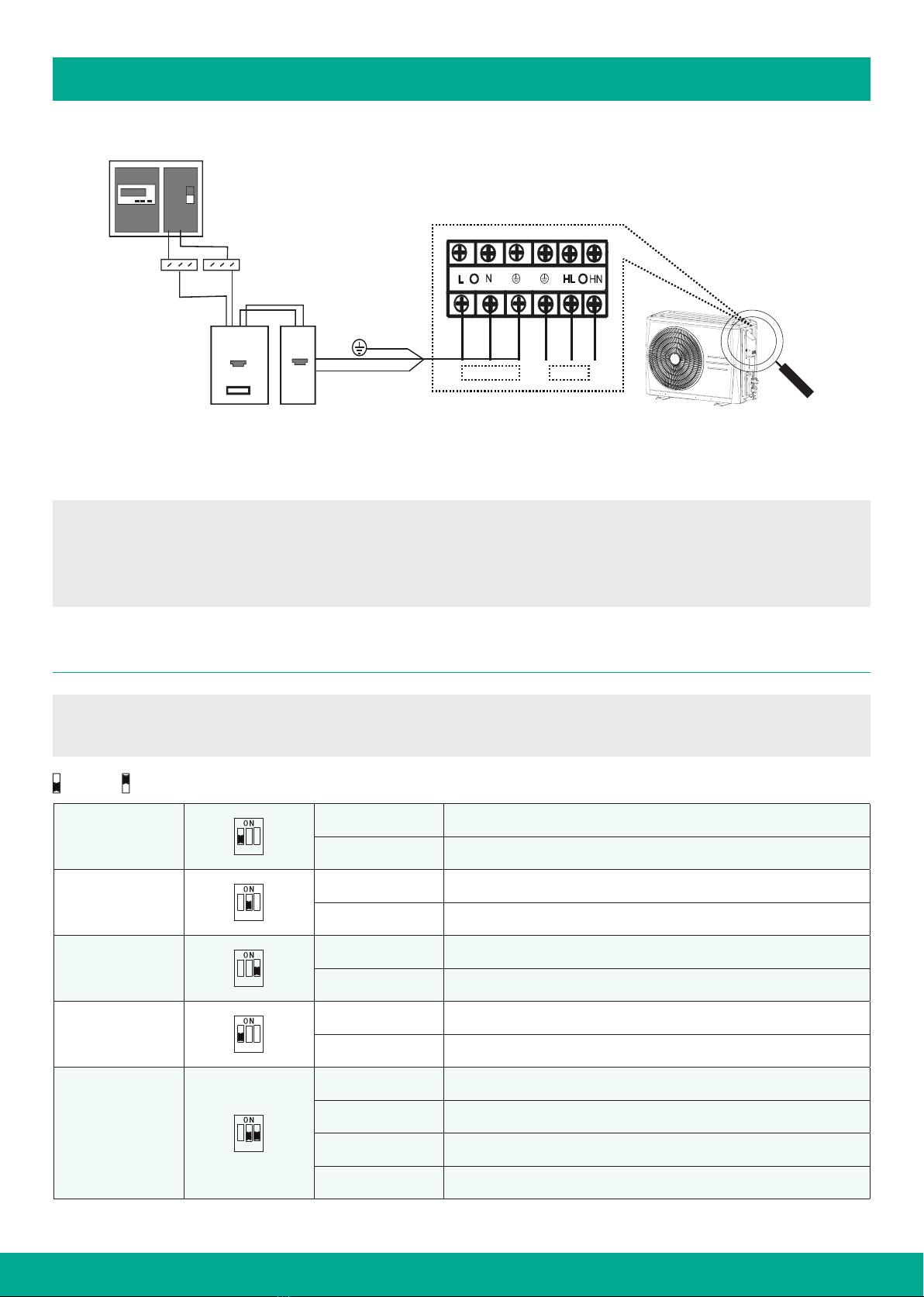
Electric connection work must comply with the instructions of the
local power company and electric utility, as well as the manual.
Never use wiring and fuses with incorrect rated current as it can
result in equipment failure and pose a fire hazard.
Do not insert fingers, rods or other objects into the air inlet or outlet.
When the fan is rotating at high speed, it will cause injury.
Never use a flammable spray such as hair spray, lacquer paint near
the unit. It may cause a fire.
This appliance is not intended for use by persons (including children)
with reduced physical, sensory or mental capabilities or lack of expe-
rience and knowledge, unless they have been given supervision or
instruction concerning use of the appliance by a person responsible
for their safety. Children should be supervised to ensure that they do
not play with the appliance.
Tear apart and throw away plastic packaging bags so that children
will not play with them. Children playing with plastic bags face
danger of death by suocation.
Safely dispose of packing materials such as nails and other metal or
wood parts that could cause injuries.
Ask your dealer or qualified personnel to perform installation work in
accordance with this manual. Do not install the unit yourself. Improper
installation could result in water leakage, electric shocks or fire.
Be sure to use only specified accessories and parts for installation
work. Failure to use specified parts may result in water leakage,
electric shocks, fire, or the unit falling from its mount.
Install the unit on a foundation that can withstand its weight.
Insucient physical strength may cause the equipment to fall and
possible injury.
Perform specified installation work with full consideration of strong
wind, hurricanes, or earthquakes. Improper installation work may
result in accidents due to equipment falling.
Ensure that all electrical work is performed by qualified personnel in
accordance with local laws and regulations and this manual, using a
dedicated circuit. An inadequate capacity of the power supply circuit
or improper electrical work could result in electrical shock or fire.
Be sure to install a ground fault circuit interrupter according to local
laws and regulations. Failure to install a ground fault circuit interrupter
may cause electric shocks and fire.
Make sure all wiring is secure. Use the specified wires and ensure
that terminal connections or wires are protected from water and
other adverse external forces. Incomplete connection or axing may
cause a fire.
When making the power supply connections, arrange the wires in
such a way that the front panel can be securely fastened. If the front
panel is not securely in place, the terminals may overheat, causing
electrical shocks or fire.
After completing the installation work, check to make sure that there
is no refrigerant leakage.
Avoid direct contact with any leaked refrigerant as it may cause
severe frostbite. Do not handle the refrigerant pipes during or
immediately after operation as they can be hot or cold, depending
on the refrigerant flowing through them, the compressor, and other
refrigerant cycle components. Touching the refrigerant pipes can
cause burns or frostbite, so be sure to wait until they return to normal
temperature or wear protective gloves if necessary.
Do not touch the internal parts (pump, backup heater, etc.) during
and immediately after operation. Touching the internal parts can
cause burns. To avoid injury, give the internal parts time to return
to normal temperature or, if you must touch them, be sure to wear
protective gloves.
1. SAFETY PRECAUTIONS
33
Servicing shall only be performed as recommended by the
equipment manufacturer. Maintenance and repair requiring the
assistance of other skilled personnel shall be carried out under
the supervision of the person competent in the use of flammable
refrigerants.
⚠ CAUTION
Make sure the earthing pole of the socket is well grounded and the
power supply socket and plug are dry and connected securely.
Before cleaning, turn o the breaker or unplug the unit.
After prolonged use, inspect the unit's base and fittings for damage,
as it may sink and cause injury if damaged.
Ensure the drain pipe is properly arranged for smooth draining, as
improper drainage may result in building, furniture, and other items
getting wet.
The unit must be grounded with a resistance that complies with local
laws and regulations.
Do not connect the ground wire to gas or water pipes, lightning
conductors or telephone ground wires.
Incomplete grounding may cause electric shocks.
- Gas pipes: Fire or an explosion might occur if the gas leaks.
- Water pipes: Hard vinyl tubes are not eective grounds.
- Lightning conductors or telephone ground wires: Electrical
threshold may rise abnormally if struck by a lightning bolt.
The installation height of power supply should be over 1.8m, if there
is any water spattered, separate the power supply from water.
Do not wash the unit. This may cause electric shocks or fire.
The appliance must be installed in accordance with national wiring
regulations. If the supply cord is damaged, it must be replaced by a
qualified electrician.
Do not install the unit in the following places:
- Where there is mineral oil, oil spray (eg: kitchen) or vapors.
Plastic parts may deteriorate, and cause them to come loose
or water to leak.
- Where corrosive gases (such as sulfurous acid gas) are
produced. Where corrosion of copper pipes or soldered parts
may cause refrigerant to leak.
- Where there is machinery which emits electromagnetic waves.
Electromagnetic waves can disturb the control system and cause
equipment malfunction.
- Where flammable gases may leak, where carbon fiber or
ignitable dust is suspended in the air or where volatile flammables
such as paint thinner or gasoline are handled. These types of
gases might cause a fire.
- Where the air contains high levels of salt such as near the
ocean.
- Where voltage fluctuates a lot, such as in factories.
- In vehicles or vessels.
- Where acidic or alkaline vapors are present.
- Other special environments.

1. SAFETY PRECAUTIONS
This appliance can be used by children 8 years old and above and
persons with reduced physical, sensory or mental capabilities or
lack of experience and knowledge if they are supervised or given
instruction on using the unit in a safe manner and understand the
hazards involved. Children should not play with the unit. Cleaning
and user maintenance should not be done by children without
supervision.
Children should be supervised to ensure that they do not play with
the appliance.
If the supply cord is damaged, it must be replaced by a qualified
electrician.
Concerning disconnection incorporated in the fixed wiring should be
in accordance with AS/NZS 3000.
DISPOSAL: Do not dispose this product as unsorted municipal
waste. Collection of such waste separately for special treatment
is necessary. Do not dispose of electrical appliances as municipal
waste, use separate collection facilities. Contact your local govern-
ment for information regarding the collection systems available. If
electrical appliances are disposed of in landfills or dumps, hazardous
substance can leak into the groundwater and get into the food chain,
damaging your health and well-being.
The wiring must be performed by professional technicians in
accordance with national wiring regulation and the circuit diagram
in the electrical connection section of this manual. An all-pole
disconnection device which has at least 3mm separation distance
in all pole and a residual current device (RCD) with the rating not
exceeding 30mA shall be incorporated in the fixed wiring according
to the national rule.
Confirm the safety of the installation area (walls, floors, etc.) without
hidden dangers such as water, electricity, and gas.
Before installation, check whether the user's power supply meets
the electrical installation requirements of unit (including reliable
grounding, leakage, and wire diameter electrical load, etc.). If the
electrical installation requirements of the product are not met, the
installation of the product is prohibited until the product is rectified.
When installing multiple air conditioners in a centralized manner,
please confirm the load balance of the three-phase power supply,
and multiple units are prevented from being assembled into the
same phase of the three-phase power supply.
Product installation should be fixed firmly. Take reinforcement
measures, when necessary.
NOTE
The appliance is intended to be permanently connected to the water
mains and not connected by a hose-set.
About Fluorinated Gasses
This air-conditioning unit contains fluorinated gases. For specific
information on the type of gas and the amount, please refer to
the relevant label on the unit itself. Compliance with national gas
regulations shall be observed.
- Installation, service, maintenance and repair of this unit must be
performed by a certified technician.
- Product uninstallation and recycling must be performed by a
certified technician.
- If the system has a leak-detection system installed, it must be
checked for leaks at least every 12 months. When the unit is
checked for leaks, proper record-keeping of all checks is strongly
recommended.
⚠ CAUTION
Generally, the ambient air temperature of the unit must be above
-15°C and below 43°C.
Install safety valve to water inlet, the largest torque of safety valve
shouldn’t be more than 80N.m.
Please make sure water tank is upright. Install in a location that
can prevent unit toppling and falling (e.g. balcony or corner). Install
the unit in an open space, to avoid being blown down by strong
wind (especially in the are with strong wind), please fix water tank
according to operation manual.
4

2. GENERAL INTRODUCTION
1
2
3
4
5
5 No. NAME
1 Power cord enclosure
2 High pressure valve
3 Low pressure valve
4 Air outlet
5 Air inlet
6
7
10
8
9
5
4
5
6
7
8
9
10
11
11
12
12
1
2 1
2
3
4
No. NAME
1 Magnesium rod insertion port
2 Foam filling port
3 Reserved port
4 Water outlet
5 Temperature pressure safety valve
6 Water tank temperature sensor
7 Handle
8 Refrigerant gas pipe
9 Refrigerant liquid pipe
10 Water inlet
11 Drain outlet
12 Electric auxiliary heat
2.1 OUTDOOR UNIT
2.2 WATER TANK
200L WITHOUT HEATER 300L WITH HEATER
Fig. 2-1
Fig. 2-2
5

2. GENERAL INTRODUCTION
2.3 SPECIFICATIONS
Fig. 2-3
-15
55
50
60
20 -10 43 46
Ambient temperature
Leaving water temperature
Ambient
temperature
Leaving water
temperature
-15~-10 50
-10~43 60
43~46 55
6
GENERAL
MODEL NUMBER
EE-HWS-RCHP-200
EE-HWS-RCHP-200-1
EE-HWS-RCHP-200E
EE-HWS-RCHP-200E-1
EE-HWS-RCHP-300
EE-HWS-RCHP-300-1
EE-HWS-RCHP-300E
EE-HWS-RCHP-300E-1
Ambient temperature ºC -15~46
Leaving water temperature ºC 20~63
Heating
Capacity W 2600
Input W 1000
STC values 33(Zone3) / 36(Zone4) 33(Zone3) / 36(Zone4) 32(Zone3) / 35(Zone4)
32(Zone3) / 35(Zone4)
Hot water yield m3/h 0.0441/ 0.0562
Refrigerant
piping
Refrigerant piping mm(inch) Ø6.35 / Ø1/4’
Gas side mm(inch) Ø9.52 / Ø3/8’
Max. height dierence m 10
Max. refrigerant pipe length
m 20
Design pressure MPa 3
OUTDOOR
UNIT
Outdoor unit power supply V/N/Hz 220-240/1/50
Max. current A 4.4 13.5 4.4 13.5
Compressor Type Rotary
Fan
Type AC
Air flow (H/L) m3/h 1250/769
Air side heat exchanger Type Hydraulic aluminum fin + Inner grooved copper tube
Throttle Type Electric expansion valve
Outdoor sound pressure level dB(A) 54
Dimension
Unit dimension (L*W*H) mm 804*327*555
Packing dimension (L*W*H) mm 845*390*610
Net weight kg 29
Gross weight kg 32
Refrigerant
Type R134a
Charged volume g 900
INDOOR
UNIT
Tank volume L 200 200 300 300
Electric
heater
Capacity kW / 2 / 2
Power supply V/N/Hz 220-240/1/50 220-240/1/50 220-240/1/50 220-240/1/50
Dimension
Unit dimension(W*D*H) mm 505*505*1665 505*505*1665 580*580*1735 580*580*1735
Packing dimension(W*D*H) mm 1775*635*590 1775*635*590 1835*690*670 1835*690*670
Net weight kg 73 73 96 96
Gross weight kg 83 83 108 108

3. BEFORE INSTALLATION
3.1 ACCESSORIES
7
Flexible hose (pair)
2 x 2.5m refrigerant piping (6.35mm &
9.52mm)
Single bend copper tails and
lagging c/w 15mm connections
Tempering valve c/w cover
2 x Connector
(15 male*15 screw)
TPR valve fitting 15mm 1 x 15mm copper straights
3 x 15mm copper bends
Electrical circuit breaker, 20A
Electrical - RCBO enclosure
Electrical - single phase
isolator 20A
ELECTRICAL
Table 3-1

3. BEFORE INSTALLATION
3.2.1 OUTDOOR UNIT INSTALLATION AND MAINTENANCE SPACE.
3.2.2 WATER TANK INSTALLATION AND MAINTENANCE SPACE.
3.2 SPACE FOR MAINTENANCE
≥300mm
≥1500mm
Air outlet
≥200mm
≥600mm
≥600mm
Use bolt to fix
≥200mm
≥500mm
Fig. 3-1 Fig. 3-2
≥300mm
≥1500mm
Air outlet
≥200mm
≥600mm
≥600mm
Use bolt to fix
≥200mm
≥500mm
Rain
Rainshed
Fig. 3-3 Fig. 3-4
NOTE
It is necessary to reserve enough installation and maintenance space during installation according to the following figures.
NOTE
If the water tank is completely installed outdoors, a rain shelter can be installed.
When the water tank is installed outdoors, the distance between the water tank and the fence should not be less than 200mm.
When the water tank is installed indoors, the distance between the water tank and the wall should not be less than 600mm.
8

4. INSTALLATION PROCEDURE
4.1 DIMENSION SKETCH
4.1.1 OUTDOOR UNIT.
Strong
wind
CORRECT INCORRECT
B
A
DE
C
DIMENSION AND MOUNTING DIMENSION
A B C D E
803.6 554.9 311.6 452.4 137.5
Table 4-1
NOTE
This heat pump unit must be installed, repaired or moved only by an authorised installer or technician.
When installing the heat pump, it is important to locate it in an area that is not exposed to direct sunlight or other sources of heat.
If this is not possible, a cover should be added to protect the unit from direct sunlight.
When installing on a roof, make sure it is a flat surface that can handle the weight of the unit.
Make sure to securely install the unit to avoid any abnormal noise or vibration.
Remove obstacles nearby. A narrow circulation space may influence the performance of the unit..
Place the unit as close to the water tank as possible, as long as the installation requirements are met.
When installing in a location near the sea or with strong winds, it is important to secure the unit against a wall, as shown in Figure 4-1, or to
provide protection from the elements, to ensure it correct operation.
When installing the unit in a basement, interior room, or other confined space, be mindful of air discharge and circulation both inside and
outside the unit. Ensure that the air flow is at least 1250m3/h.
Fig. 4-1
Fig. 4-2 Fig. 4-3
Please fix the four bases of the outdoor unit on the flat ground with
bolts.
9

4. INSTALLATION PROCEDURE
4.2 DRAIN HOLE POSITION
Water outlet
connection
pipe/gasket
Fig. 4-6
4.1.2 WATER TANK.
H
A
Fig. 4-4 Fig. 4-5
Please install the water tank fixing strip as shown in the figure to
ensure that the water tank is stably fixed.
DIMENSION
MODEL A H
200L 505 1665
300L 580 1735
Table 4-2
Drain
outlet
Fig. 4-7
10

Drain
outlet
4. INSTALLATION PROCEDURE
4.3 PIPE CONNECTION
4.3.1 UNIT CONNECTION SKETCH
Fig. 4-8
OUTDOOR UNIT WATER TANK
Hot water outlet
Cold water inlet
6.35
9.52
GUTTERS
GUTTERS
NOTE
The water tank temperature can be set from 20ºC to 60ºC.
The minimum water inlet pressure is not less than 150Pa, and the maximum is not more than 650Pa.
If the inlet water pressure is less than 150Pa, a pump should be installed at the water inlet.
To guarantee the safety usage of tank, a reducing valve should be installed in the water inlet pipe, if the water
pressure exceeds 650Pa.
It is strongly recommended to use thread seal tape for sealing when connecting water pipes and valves.
11
NAME Water end user Stop valve Water mixing valve
ICON
NAME Safety valve
(if required) Gutter
ICON
Table 4-2

4. INSTALLATION PROCEDURE
4.3 PIPE CONNECTION (CONTINUED)
4.3.2 PTR VALVE
The valve body unloading pressure is 850kPa, unloading tempera-
ture is 99ºC, and the valve body opening energy value is 46kW, for
more details refer to certificate No:WMK26608.
PTR valve is tightened with a 68N.m torque wrench. Apply sealant to
the first 3 turns of screw thread before installation; After installation,
the outlet of the drain pipe shall be installed face down, and the
thread turns that are not screwed into the PTR valve shall be less
than 3 turns.
Before filling the water tank, the PTR valve must be installed properly.
The PTR valve should be checked every 6 months to make sure that
there is no restriction of the valve. Please beware of hot water from
the valve. The drainage pipe should be well insulated in order to
prevent water inside pipe from freezing in cold weather.
4.3.3 STOP VALVE INSTRUCTION
In general, the shape of stop valve and names of each part are
shown in Fig.4-10.
Eect of stop valve:
- Stop the system when the unit is working.
- When water tank connects with the outdoor unit, vacuum
and add refrigerant through it.
- Stop the system and then recycle refrigerant to outdoor unit
when maintaining.
Open and close the stop valve:
- Open: dismantle the bonnet by wrench and insert an
*Allen key to spool, open the stop block anticlockwise
and then tighten the bonnet.
- Close: use a wrench to dismantle the bonnet and insert
an Allen key to spool, close the stop block clockwise and
then tighten the bonnet.
4.3.3 CONNECTION LENGTH OF OUTDOOR UNIT AND WATER
TANK PIPE AND HEIGHT DIFFERENCE REQUIREMENTS:
MAX.
LENGTH
m
MAX. HEIGHT
DIFFERENCE
m
STANDARD
LENGTH
m
STANDARD
HEIGHT
DIFFERENCE
m
20 10 2.5 0
Table 4-4
⚠ CAUTION
Before water heater runs, please make sure every stop valve
has been opened.
NOTE
Do not let air, dust, or other impurities fall into the pipe system
during installation.
The connecting pipe should not be installed until the indoor and
outdoor units have been fixed already.
Keep the connecting pipe dry, and do not let moisture in during
installation.
When connecting copper pipe, please wrap it with thermal
insulation material.
Handle
Fig. 4-9
Fig. 4-10
Drainage pipe
*Allen key
Bonnet
Connection nut
Ball-shape cushion
Connection pipe
Valve spool
Spool
12

4. INSTALLATION PROCEDURE
4.4 VACUUM DRYING
4.4.1 PURPOSE
Vacuum drying should be performed in order to remove moisture
and non-condensible gases from the system. Removing moisture
prevents ice formation and oxidization of copper piping or other
internal components. The presence of ice particles in the system
would cause abnormal operation, whilst particles of oxidized copper
can cause compressor damage. The presence of non-condensible
gases in the system would lead to pressure fluctuations and poor
heat exchange performance.
4.4.2 PROCEDURE
Fig. 4-11
OUTDOOR UNIT
Pressure gauge
Vacuum pump Service port
1. Gas pipe stop valve
2. Liquid pipe stop valve
1
2
13

ITEM DESCRIPTION IMAGE NOTE
1
Connect the (low pressure side)
hose of a pressure gauge to the
outdoor unit gas pipe stop valve.
Before performing vacuum drying, make sure that all
the outdoor unit stop valves are firmly closed.
2Connect the hose to the
vacuum pump.
1. Mixing of pump lubricant with compressor oil could
cause compressor malfunction and a one-way valve
should therefore be used to prevent vacuum pump
lubricant seeping into the piping system.
2. Using a vacuum pump with a discharge in excess
of 4L/s and a precision level of 0.02mmHg is
recommended.
3Connect the outdoor unit gas pipe stop
valve to water tank gas pipe.
4Connect the outdoor unit liquid pipe
stop valve to water tank liquid pipe.
5
Start the vacuum pump and then open
the pressure gauge valves to start
vacuum the system.
6After 15-20 minutes, close the pressure
gauge valves.
7
After a further 5 to 10 minutes check
the pressure gauge. If the gauge has
returned to zero, check for leakages in
the refrigerant piping. If the gauge is
no change, then vacuum drying is OK.
8
Re-open the pressure gauge valves
and continue vacuum drying for at
least 20 minutes and until a pressure
dierence of 756mmHg or more has
been achieved. Once the pressure
dierence of at least 756mmHg has
been achieved, continue vacuum
drying for 20 minutes.
9Close the pressure gauge valves and
then stop the vacuum pump.
10
After 1 hour, check the pressure gauge.
If the pressure in the piping has not
increased, the procedure is finished.
If the pressure has increased, check for
leakages.
After vacuum drying, keep the hoses connected
to the pressure gauge and to the outdoor unit
stop valves, in preparation for refrigerant charging
Table 4-5
4.5 REFRIGERANT CHARGE
Pipe length is 2~20m.
If the pipe length is less than 10m, there is no need to add additional refrigerant charge.
If the pipe length is more than 10m, adding additional refrigerant charge is necessary, and the rule is 20g/m for the additional pipe.
4. INSTALLATION PROCEDURE
14

5. ELECTRICAL CONNECTION
⚠ CAUTION
The heat pump must have a separate power supply with the correct rated voltage.
The external power supply to the heat pump should have ground wiring, which is linked to the ground wiring of the indoor and outdoor unit.
The wiring work should be done by qualified persons according to circuit drawing.
A leakage protector should be installed according to the National Standard concerning electrical appliance.
An all-pole disconnection device which has at least 3mm separation distance in contact points should be installed.
Power supply cords and signal wires should be arranged properly. Separate strong current wire and weak current wire, meanwhile they
can’t contact with connection pipe and valve.
Power supply with a leakage protector should be installed in a water-proof place inside the room.
Don’t do cross connection between 2 wires and signal wires must be shielded.
When power supply cord parallels with controlling wire, please put the wires to corresponding wire pipe and leave proper space between
wires.
When selecting power supply cords, please refer to the National Standard and this manual, power supply used outdoor should not lighter
than NO.57 wire in IEC 60245.
If power supply cord is damaged, to avoid danger, it must be replaced by professional person.
Do not turn on the power until the wiring has been checked thoroughly
5.1 POWER SUPPLY CORDS
5.1.1 SPECIFICATION OF POWER SUPPLY
ITEM
MODEL
POWER
MINIMUM WIRE DIAMETER
MM2 MENTAL PIPE
SYNTHETIC RESIN PIPE WIRE
Manual switch
(A)
LEAKAGE
PROTECTOR
MAX
EHEATER
POWER W
LENGTH
SUCCESSIVE
LENGTH ≤30M
GROUND
WIRE CAPACITY FUSE
With AUX. 220-240V~
50Hz 4 4
20 15
30mA
below
0.1 sec
2100
Without AUX. 2.5 2.5
Table 5-1
NOTE
Specifications of power wires above (outdoor unit power wire
and power wire that connects with water tank): H07RN-F.
Power supply provided individually (not use power supply
device).
⚠ CAUTION
Wire diameter shown in the table above and successive length
is the situation than voltage drop is in the range of 2%, when
successive length is longer than the value shown in the table,
please select wire diameter according to relative standards.
15

5. ELECTRICAL CONNECTION
5.3 ODU & AUX. POWER CONNECTION
NOTE
If the water tank has the electric auxiliary heating (AUX.) function, please follow the steps below to connect the electric auxiliary heating
power cord.
1. Remove the protective cover of the electric control box on the right side of the outdoor unit.
2. Connect the electric auxiliary heating power line on the water tank to the corresponding port on the terminal block.
Fig. 5-2
5.2 WATER TANK TEMPERATURE SENSOR INSTALLATION
Connect the water tank temperature sensor wire connector to the outdoor unit T5L connector.
Fig. 5-1
T5L
PCB
Water tank temperature sensor T5L
Fig. 5-3
Terminal block
16

5. ELECTRICAL CONNECTION
⚠ CAUTION
A leakage protector must be installed on power supply box outside the unit according to the figure above.
Power supply with leakage protector must be installed inside or installed in the place that can satisfy water-proof requirements.
This unit can be started only if it is grounded reliably.
C: E-heater power cord
1 : Electric counter
2 : Global over current and
leakage circuit breaker
3 : Electric leakage circuit breaker
4 : over current circuit breaker
Fig. 5-5
3.Outdoor unit power supply.
5.4 DIAL CODE DEFINITIONS
NOTE
The picture shown is for reference only, actual product may vary.
S1-1
1 2 3
0 Default
1 Reserve
S1-2
1 2 3
0 Without electric auxiliary heater
1 With electric auxiliary heater
S1-3
1 2 3
0 Default
1 Reserve
S2-1
1 2 3
0 Default
1 Reserve
S2-2
S2-3 1 2 3
00 Default
01 Reserve
10 Reserve
11 Reserve
Table 5-2
GND
L
N
4
3
1
0
1 2
16A
o
oo o o o
o o
Power supply E-heater
Terminal block
means 0, means 1.
17

6. CHECK
NOTE
Before switching on the unit, read following recommendations:
When the installation and parameter setting are completed, cover all the sheet metal of the unit well.
The unit should be maintained by professionals.
If the unit has failed or is in protection mode, the panel will show the relevant code. If multiple failures or protection modes occur, they
will be displayed in the order they happened. To view the parameters of the unit, press the check button. The table below outlines the
sequence of the check:
ITEM DESCRIPTION IMAGE
0 Normal display
“dF”——Defrosting
“dC”——Refrigerant recovering
“0”——When being shut down
“_” Temperature of water tank—— When operating or standby
1 Running mode "3"——Water heating
2Running air speed
"F0" ——Shut down fan
"F1" ——Low speed
"F3"—— High speed
3 T3 temp. value
4 T4 temp. value
5 T5L temp. value
6Th temp. value
7Tp temp. value
8Current
9 EEV opening degree Actual opening=display value×8
10 T5s setting temperature
11 Td setting auto start temp. of auxiliary E-heater
12 Trdh setting booting return dierence temp.
13 The third to last error
14 Penultimate error
15 The last error
16 Software version Actual version
17 Check finished Display“- -”
Table 6-1
18

7. OPERATIONS AND PERFORMANCES
⚠ CAUTION
Cut o manual switch power when the unit fails. Do not restart until the issues have been resolved.
1. Characteristics of water heating - 3 minute protection
When restarting the unit after a short shutdown, there will be a 3 minute delay before it begins operation due to the self-protect function of the
compressor.
2. During operation, if outdoor temperature is higher than normal, the fan motor will runs at low air volume or stop running.
3. During heating operation, if frost accumulates on the unit, the defrosting function will activate automatically (lasting approximately 2-7 minutes)
to maintain heating eciency. During the defrosting operation, the fan motor will temporarily stop.
4. About protection device
- When the protection device is activated, the unit will stop, but the wire control's operating indicator will continue to blink.
- If the protection device is activated, the nixie indicator will display a corresponding malfunction code.
- The protection device will activate in the following scenarios:
a) Blockage of air inlet or outlet.
b) Voltage deviates outside the range of -10% to 10% of 230V (higher or lower)
5. Starting the unit after a prolonged downtime:
- If starting the unit after a prolonged period of disuse (such as the initial start-up), you may observe rust-tinged water flowing from the tap.
This is normal and to be expected.
6. Power failure
- If there is a power failure while the unit is in use, stop all operations immediately.
- Upon restart after a power failure, the RUN indicator on the wire controller will blink slowly for several seconds to alert the user.
7. RCCB (Residual Current Circuit Breaker)
- The outdoor unit must be equipped with an RCCB. An RCCB must be installed between the user's power supply and the outdoor unit.
- If the unit fails to function, but there is no power failure, check the RCCB switches first.
- Before operating the RCCB, make sure that the user-installed switch is in the o position.
19

8. MAINTENANCE
8.1 CONFIRMATION BEFORE RUNNING
1. Make sure the wires are grounded
2. Turn on power supply switch for 12 hours before running.
8.2 TROUBLESHOOTING
Before requesting a service or repair check the following:
Non-mechanical malfunction
1. When heating water, it is normal for cold water to expand and
cause some leakage from the valve. This is a safety feature, so do
not attempt to block it.
- If a significant amount of water is flowing, it indicates that the safety
valve is not functioning properly.
2. Slow water heating in the tank
- During winter, the low ambient temperature (around 0ºC) can
reduce the heating eciency, causing a slower heating process.
- If customer needs to use hot water, it is recommended to start the
unit in advance.
3. Automatically starting or stopping.
- The cause could be an incorrect setting of the timer.
4. If the heat pump is not working.
- Verify if the power is turned on.
- Check if the manual switch is in the on position.
- Determine if the fuse has blown.
- Confirm if the protection device has started (indicator lights).
- Make sure the timer is set correctly (operation lamp is lit).
5. Low heating performance.
- Check if the air outlet and inlet are obstructed.
⚠ CAUTION
If the following occurs stop operation, manually cut o the
power supply, and contact the dealer or service center:
- Ineffective ON/OFF function.
- Frequent tripping of the fuse or RCCB.
Before leaving the heater unused for an extended period of
time, please follow these steps:
- Empty the water from the tank and pipes and close all valve
bodies.
After leaving the heater unused for an extended period of
time, please check the following:
- Verify if the air inlet and outlet of the unit are obstructed and
clean if necessary.
- Ensure that the water pipes and valves are not damaged or
blocked.
- It is recommended to inspect the anode material every six
months and replace it if it is exhausted.
8.3 AFTER SALES SERVICE
In case of malfunctions, please cut o the power switch and contact
after-sales service centre or technical service department, for de-
tailed information please refer to User Service Guide.
8.4 IMPORTANT REFRIGERANT
INFORMATION
This product contains fluorinated gas and must not be released
into the air.
Refrigerant type: R134a; Volume of GWP: 1430;
GWP=Global Warming Potential
FACTORY CHARGE
Refrigerant/kg tonnes CO2equivalent
0.9 1.29
Table 8-1
NOTE
Frequency of Refrigerant Leak Inspections:
1. For equipment containing 5-50 tonnes of CO2 equivalent of
fluorinated greenhouse gases, checks must be done at least
once a year, or every 24 months if a leakage detection system
is installed.
2. For equipment containing 50-500 tonnes of CO2 equivalent
of fluorinated greenhouse gases, checks must be done at least
every six months, or every 12 months if a leakage detection
system is installed.
3. For equipment containing 500 tonnes or more of CO2 equiv-
alent of fluorinated greenhouse gases, checks must be done
at least every three months, or every six months if a leakage
detection system is installed.
4. Non-hermetically sealed equipment filled with fluorinated
greenhouse gases can only be sold to the end user if the
installation is performed by a certified technician.
5. Only certified technicians are authorized to perform
installation, operation, and maintenance tasks..
20
This manual suits for next models
8
Table of contents
Other Emerald Water Heater manuals
Popular Water Heater manuals by other brands

Rheem
Rheem RUUD High-Power Commercial Water Heater Specifications

Vulcan-Hart
Vulcan-Hart 244 series Owner's guide and installation instructions

PVI
PVI MAXIM Specification sheet

Elwa
Elwa HOTRUN-X24 Setup manual

Hubbell
Hubbell 280-3 Installation, operation and maintenance manual

Pentair
Pentair JUNG PUMPEN BAUFIX 200 instruction manual