Emerson Network Power RDU-S User manual

RDU-S Rack Data Unit
User Manual
Version
V1.4
Revision date
December 13, 2011
BOM
31012350
Emerson Network Power provides customers with technical support. Users may contact
the nearest Emerson local sales office or service center.
Copyright © 2010 by Emerson Network Power Co., Ltd.
All rights reserved. The contents in this document are subject to change without notice.
Emerson Network Power Co., Ltd.
Address: No.1 Kefa Rd., Science & Industry Park, Nanshan District 518057, Shenzhen
China
Homepage: www.emersonnetworkpower.com.cn
E-mail: support@emersonnetwork.com.cn


Contents
Chapter 1 Overview ............................................................................................................................................................1
1.1 Product Introduction..............................................................................................................................................1
1.1.1 Appearance...............................................................................................................................................1
1.1.2 Indicators...................................................................................................................................................1
1.1.3 Ports..........................................................................................................................................................2
1.2 Technical Specifications .......................................................................................................................................3
1.2.1 Input Specifications ...................................................................................................................................3
1.2.2 Output Specifications.................................................................................................................................3
1.2.3 Ambient Specifications ..............................................................................................................................4
1.2.4 Mechanical Specifications .........................................................................................................................4
1.3 Options .................................................................................................................................................................4
Chapter 2 Installation ..........................................................................................................................................................5
2.1 Installation Preparation.........................................................................................................................................5
2.2 Installation Tool.....................................................................................................................................................5
2.3 Installing Data Unit................................................................................................................................................6
2.3.1 Installation Hole Position...........................................................................................................................6
2.3.2 Installing The Data Unit In A Standard 19” Rack .......................................................................................6
2.3.3 Installing The Data Unit On The Wall ........................................................................................................7
Chapter 3 Connection .........................................................................................................................................................8
3.1 Connection Notes .................................................................................................................................................8
3.2 Connecting Sensor Ports......................................................................................................................................8
3.2.1 Connecting 1-Wire Sensor Port.................................................................................................................8
3.2.2 Connecting DI1, DI2 And DI3 Ports...........................................................................................................9
3.2.3 Connecting IRM Sensor Port...................................................................................................................10
3.3 Connecting Serial Ports......................................................................................................................................11
3.4 Connecting Relay Ports......................................................................................................................................12
Chapter 4 Parameter Setting.............................................................................................................................................13
4.1 Connecting Data Unit With Computer.................................................................................................................13
4.2 Setting HyperTerminal........................................................................................................................................13
4.3 Powering On.......................................................................................................................................................14
4.3.1 Checking Before Powering On ................................................................................................................14
4.3.2 Checking After Powering On ...................................................................................................................14
4.4 Logging Onto Data Unit ......................................................................................................................................15
4.5 Setting IP Address..............................................................................................................................................15
4.6 Restarting Data Unit............................................................................................................................................16

Chapter 5 Software Operation...........................................................................................................................................17
5.1 Login...................................................................................................................................................................17
5.2 Monitor Interface Operation Description .............................................................................................................18
5.2.1 Environmental..........................................................................................................................................18
5.2.2 PDU.........................................................................................................................................................20
5.2.3 Camera....................................................................................................................................................25
5.3 Control Interface Operation Description..............................................................................................................27
5.4 Configure Interface Operation Description..........................................................................................................29
5.5 Events Interface Operation Description ..............................................................................................................39
5.6 History Interface Operation Description..............................................................................................................41
5.7 System Information Interface Operation Description...........................................................................................43
5.8 Logout.................................................................................................................................................................43
Chapter 6 Troubleshooting................................................................................................................................................44
Appendix 1 Command Lines.............................................................................................................................................45
1. Overview...............................................................................................................................................................45
2. Main Command Lines...........................................................................................................................................45

Chapter 1 Overview 1
RDU-S Rack Data Unit User Manual
Chapter 1 Overview
This chapter gives a brief introduction to the appearance, indicators, ports, technical specifications and options of
RDU-S rack data unit (data unit for short).
1.1 Product Introduction
The data unit is an intelligent acquisition system developed by Emerson to monitor the environment in rack and IDC
machine room. It is also suitable for other applications, such as small base station environment monitoring, power
equipment & environment monitoring in telecom machine room, power grid monitoring and bank ATM machine
monitoring. When configured with a proper sensor or proper sensors, it can detect corresponding electric signals and
non-electric signals in real time. The small profile design makes it suitable for installation in small space in the rack.
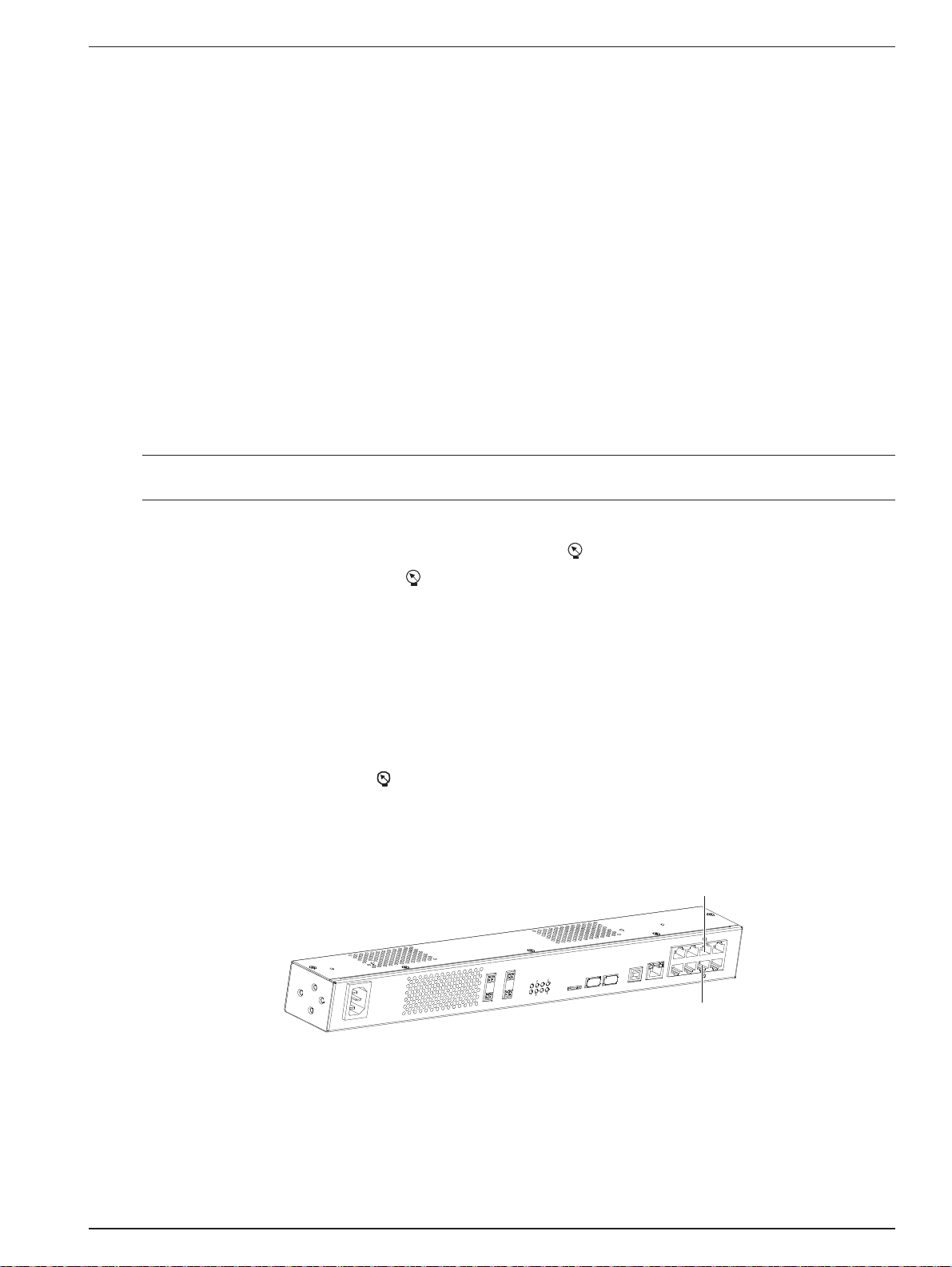
1.1.1 Appearance
The appearance of the data unit is shown in Figure 1-1.
100-a
InputDO212VGND
DO112VGND
USBUSB
MicroSD
USBCONFIG
ETH
DI1
DI2
DI3
COM1
DO1
DO2
ALARM
POWER
RUN
240V
TH_BUS
COM2
COM1
12
TH_BUS
COM2
Figure 1-1 Appearance
1.1.2 Indicators
The indicators are located on the front panel, as shown in Figure 1-2. Their descriptions are listed in Table 1-1.
100-a
InputDO212VGND
DO112VGND
USBUSB
MicroSD
USBCONFIG
ETH
DI1
DI2
DI3
COM1
DO1
DO2
ALARM
POWER
RUN
240V
TH_BUS
COM2
COM1
12
TH_BUS
COM2
ALARM
POWER
DO1
DO2RUN
Indicators
Power indicator Alarm indicator
Relay output indicators
Running indicator
Amplified figure of indicators
COM1
COM2
TH_BUS
TH_BUS communication indicator
Serial port indicators
Figure 1-2 Indicator position

2 Chapter 1 Overview
RDU-S Rack Data Unit User Manual
Table 1-1 Indicator descriptions
Silkscreen
Definition
Color
Status
Descriptions
DO1, DO2
Relay output indicators
Yellow
On
The relay is closed
Off
The relay is open
POWER
Power indicator
Green
On
The data unit is powered on normally
Off
The data unit is not powered on
ALARM
Alarm indicator
Red
On
The data unit has an critical alarm
Blinking
The data unit has an warning alarm
Off
The data unit is starting up or normal
RUN
Running indicator
Green
Blinking
The data unit is operating normally
Off
The data unit is starting up
TH_BUS
TH_BUS communication
indicator
Green
Blinking
The data unit is receiving or sending data
Off
The data unit is not receiving or sending data
COM1, COM2
S
erial port indicators
Green
Blinking
The serial port is receiving or transmitting data
Off
The serial port is not receiving or transmitting data
1.1.3 Ports
The ports of the data unit are located on the front panel, as shown in Figure 1-3.
100-a
InputDO212VGND
DO112VGND
USBUSB
MicroSD
USBCONFIG
ETH
DI1
DI2
DI3
COM1
DO1
DO2
ALARM
POWER
RUN
240V
TH_BUS
COM2
COM1
12
TH_BUS
COM2
DI1 port
Amplified figure of RJ45 ports
DI1DI3
COM1
DI2TH_BUS
COM2
RJ45 ports
Power input port 12Vdc power
ground port
Relay ports USB ports USB CONFIG port
Ethernet port
Micro SD
card slot
12Vdc power
output port
DI2 port
DI3 port 1-wire sensor port
1-wire sensor port
Serial ports
IRM sensor port
Figure 1-3 Port position
The definitions, functions and features of the ports are listed in Table 1-2.
Table 1-2 Port descriptions
Silkscreen
Port
Functions and features
100
-240V ~
Input
Power input port
Adopt power socket to feed power to the data unit. The power input
range is 100Vac ~ 240Vac
DO1, DO2
Relay ports
Output relay status
12V
12Vdc power output port
Feed power to external sensor (12Vdc power)
GND
12Vdc power ground port
12Vdc power ground
Micro SD
Micro SD card slot*
Support 2G, 4G or 8G Micro SD card to store video information and
configuration file
USB1, USB2
USB ports
Provide two A type ports of 2.0 standard; capable of recognizing
standard U disk, getting USB camera image and connecting GPRS
Modem
USB CONFIG
USB CONFIG port
Display the current IP and restore the default password

Chapter 1 Overview 3
RDU-S Rack Data Unit User Manual
Silkscreen
Port
Functions and features
ETH
Ethernet port (RJ45 port)
10M/100M, half/full-duplex self-adaptive; cable auto-crossing function;
supportive of IEEE802.3 protocol
DI1, DI2, DI3
DI1, DI2, DI3 ports (RJ45 ports)
Connect to digital sensors. Each port can connect up to four digital
sensors
TH_BUS
IRM sensor port (RJ45 port)
Connect to IRM series temperature sensor, temperature & humidity
sensor
COM1, COM2
Serial ports (RJ45 ports)
COM1 serial port is compatible with RS485, RS422 and RS232
communication modes; COM2 serial port is compatible with RS485 and
RS232 communication modes
1-wire sensor port (RJ45 port)
Connect to 1-wire sensor
Note*: After unplugging and plugging the Micro SD card, the data unit must be restarted to read the data
Except for the Ethernet port, the pin definitions of the RJ45 ports are listed in Table 1-3.
Table 1-3 Pin definitions of RJ45 ports
Pin No.
RJ45 ports
(1-wire)
DI1, DI2, DI3
TH_BUS
COM1
COM2
1
VCC (5Vdc)
12Vdc
12Vdc
R+
NC
2
1-wire signal
NC
NC
R-
NC
3
NC
D1
NC
TXD
TXD
4
NC
GND
GND
GND
GND
5
NC
GND
NC
GND
GND
6
NC
D2
NC
RXD
RXD
7
NC
D3
D+
T+/D+
D+
8
GND
D4
D-
T-/D-
D-
1.2 Technical Specifications
1.2.1 Input Specifications
The input specifications of the data unit are listed in Table 1-4.
Table 1-4 Input specifications
Input parameters
Corresponding port
Measurement accuracy
Descriptions
1
-wire
sensor
input
1
-wire
signal
1
-wire
sensor port
The
final accuracy is
determined by the used
sensor
Capable of measuring temperature and
humidity.
The 1-wire sensor can also be
connected with the digital signal from water
sensor, door magnet sensor, and so on
D
igital signal input
DI1, DI2, DI3 ports
-
Capable of measuring the digital signal
from door magnet sensor, smoke sensor
and infrared sensor
PDU input
Serial ports
-
Capable of connecting Switched PDU,
Metered PDU and Mps PDU
IRM sensor input
IRM sensor port
The final accuracy is
determined by the used
sensor
C
apable of measuring temperature and
humidity
1.2.2 Output Specifications
The output specifications of the data unit are listed in Table 1-5.
Table 1-5 Output specifications
Output parameters
Specification
Descriptions
Relay output
Route number
Two routes
S
upportive of two triggering m
odes: level mode
and pulse mode
Output contact
Relay normally open contact output
Contact capacity
5A/24Vdc; 5A/220Vac

4 Chapter 1 Overview
RDU-S Rack Data Unit User Manual
Output parameters
Specification
Descriptions
Sensor power
output
12Vdc output
11.5Vdc ~ 12.5Vdc, maximum output
current: 0.8A
The output current is the total current which the
sensor power can provide.
The total power
consumption of 12Vdc power
does not exceed
10W
USB port output
Maximum output current: 500mA
-
1.2.3 Ambient Specifications
The ambient specifications of the data unit are listed in Table 1-6.
Table 1-6 Ambient specifications
Item
Requirement
Application location
Indoor
Working temperature*
0ºC ~ 45ºC
Relative humidity
5%RH ~ 95%RH (non-condensing)
Working environment
Dust: compliant with GR-63 indoor standard. No corrosive gas, flammable gas, oily mist, steam,
water drops or salt
Air pressure
70kPa ~ 106kPa
Storage temperature
-40ºC ~ +70ºC
Cooling
Natural cooling
Note*: It is the working temperature of the data unit, not including the sensors connected with it. Make sure that the used sensors
will not be damaged within the temperature range
1.2.4 Mechanical Specifications
The mechanical specifications of the data unit are listed in Table 1-7.
Table 1-7 Mechanical specifications
Dimensions (L × W × H)
Weight
440mm × 44.2mm × 55mm
≤1.5kg
1.3 Options
The options of the data unit are listed in Table 1-8.
Table 1-8 Options
Classification
Optional model
D
igital sensors
1. ER-ST01P infrared sensor (RJ45 port)
2. EE
-SD01S smoke sensor (RJ45 port)
3. ER
-DR02J door magnet sensor (RJ45 port)
4. EW
-WT01B water sensor (RJ45 port)
5.
IRM-S01W (5m, 10m) water sensor(RJ45 port)
6
. SN-TH temperature & humidity sensor (RJ45 port)
7
. SN-2D door dry contact sensor (RJ45 port)
8
. SN-3C dry contact sensor (RJ45 port)
9
. IRM-S01T intelligent temperature sensor (RJ45 port)
10
. IRM-S02TH intelligent temperature/humidity sensor (RJ45 port)
11. SN-L leak detection sensor (RJ45 port)
Relay connectors
1. SL79LED stroboscopic alarm (two cables, non-RJ45 port)
2. HX-F8502 acousto-optic alarm (two cables, non-RJ45 port)
C
ameras
1. KS-188 USB camera
2. ICAM-01 camera (with PTZ control)
Installation options of sensors
1. IDS-08 5cm simple installation support
2. Mushroom head magic paste
3. 16mm gummed magic paste
4. CT3Y 3cm
round magnet
5. RJ45 three-way connector

Chapter 2 Installation 5
RDU-S Rack Data Unit User Manual
Chapter 2 Installation
This chapter expounds the installation preparation, installation tools and installation method of the data unit.
2.1 Installation Preparation
Notes
To avoid personnel injury and damage to the device in installation and use of the data unit, take the following
precautions:
zNever put the data unit in watery places and always prevent liquid from entering the data unit.
zIn installation and connection, wear anti-static clothing and an anti-static wrist strap; if anti-static clothing and
anti-static wrist strap are not available, wash your hands instead and dry them before installation and
connection.
zArrange the wires properly. Do not put any heavy objects on the wires or stamp the wires.
zGround the data unit properly.
zAlways cut off the power before performing any hardware operation.
Operating environment
The data unit must be installed indoors. The temperature and humidity should meet the product specifications (see
Table 1-6).
EMI
For EMI purpose, take the following measures:
zDo not connect the working ground of the data unit to ground of electrical power equipment or lightning ground.
Instead, place them away from each other as far as possible.
zKeep the data unit away from large-power radio transmitters, radar transmitters and high-frequency large current
electrical equipment.
zTake electromagnetic shielding measures if necessary.
Heat dissipation
The heat dissipation requirements of the data unit are given as follows:
zKeep the data unit as far as possible from heat sources.
zKeep at least 10mm clearances around the data unit for adequate heat dissipation.
2.2 Installation Tool
The installation tools of the data unit are listed in Table 2-1.
Table 2-1 Installation tools
Tool
Specification
Tool
Specification
Crimping pliers for network cable
Standard
Slotted screwdriver
100mm, 200mm
Electrician diagonal cutting pliers
150mm
Wire cutter
Maximum 300mm2
Electrician long nose pliers
150mm
Digital multimeter
Three and a half digit
Crossed screwdriver
100mm, 200mm
Drill
With a Φ6aiguille

6 Chapter 2 Installation
RDU-S Rack Data Unit User Manual
2.3 Installing Data Unit
The data unit can be installed in a standard 19”rack through hangers (accessories) or a round hanger (accessory). It
can also be mounted on the wall through hangers.
2.3.1 Installation Hole Position
The hangers are installed on the side panels and the round hanger is installed on the back panel or top panel. The
installation holes on the panels are shown in Figure 2-1.
1
2
356
4
7
89
10
Top panel
Back panel
Left panel
Figure 2-1 Positions of installation holes
The installation holes ķand ĸ(also two installation holes on the right panel) are used for installing the hangers
and the installation holes Ĺ~ ŀare used for installing the round hanger.
2.3.2 Installing The Data Unit In A Standard 19”Rack
Installing the data unit through hangers
1. Fasten two hangers respectively to both sides of the data unit with M3 screws, as shown in Figure 2-2.
ᆹ㻵ᆄ
ᤲ㙣
Installation hole
Hanger
Figure 2-2 Installing hangers (rack mounting)
The completed status is shown in Figure 2-3.
Hanger Hanger
Processing unit
Fixing hole
(4 pcs)
Figure 2-3 Completed status figure
2. Put the data unit onto the guide rails in the rack and push it into the rack completely.
3. Wrench M6 screws into the fixing holes (see Figure 2-3) of the hangers to fasten the data unit onto the rack.

Chapter 2 Installation 7
RDU-S Rack Data Unit User Manual
Installing the data unit through a round hanger
1. Fasten the round hanger onto the top panel or back panel of the data unit with an M3 screw, as shown in
Figure 2-4.
ᆹ㻵ᆄ
ശᤲ㙣
ᮠᦞঅݳ
Installation hole
Round hanger
Processing unit
Figure 2-4 Installing round hanger
2. Hang the data unit onto the vertical pole in the rack through the round hanger.
2.3.3 Installing The Data Unit On The Wall
1. Fasten two hangers respectively to both sides of the data unit with M3 screws, as shown in Figure 2-5.
Note
The installation direction of the hangers in wall mounting mode is opposite to that in rack mounting mode.
ᤲ㙣
ᆹ㻵ᆄ
Hanger
Installation hole
Figure 2-5 Installing hanger (wall mounting)
2. Use a drill (aiguille: Φ6) to drill four holes (depth: 70mm) on the wall according to the dimensions in Figure 2-6 and
knock four plastic expansion pipes into the holes.
45.8
31.3
Figure 2-6 Hole dimensions (unit: mm)
3. Put the data unit in the position, and wrench self-tapping screws into the plastic expansion pipes through the fixing
holes of the hangers to fix the data unit on the wall.
8 Chapter 3 Connection
RDU-S Rack Data Unit User Manual
Chapter 3 Connection
This chapter expounds the connection of the data unit, including connection notes, and connecting the sensor ports,
serial ports, relay port and multiple signals of RJ45 ports.
3.1 Connection Notes
The connection notes are given as follows:
1. The power and external signals that are connected to the data unit must be SELV circuits. The isolation and
insulation must be enhanced between them and the power grid.
2. When making RJ45 port cables, pay attention to the pin definitions to avoid wrong connection. For the pin
definitions, refer to Table 1-3 and the pin definition figures of the RJ45 ports in this chapter.
3.2 Connecting Sensor Ports
Note
Refer to the corresponding sensor instructions to carry out the installation and wiring operation.
Before sent to the data unit, the site signals should be transformed into electrical signals by sensors. The data unit
provides six sensor ports (silkscreen: DI1, DI2, DI3, TH_BUS and ) to connect the sensors.
zThe 1-wire sensor port (silkscreen: ) is supportive of 1-wire sensor.
zThe DI1, DI2 and DI3 ports are supportive of digital sensors, including infrared sensor, water sensor, door
magnet sensor, smoke sensor, and so on.
zThe IRM sensor port (silkscreen: TH_BUS) is supportive of IRM series sensor, including temperature sensor and
temperature & humidity sensor.
If the used sensor needs 12Vdc power, the 12Vdc power output port (see Figure 1-3) of the data unit can be used.
3.2.1 Connecting 1-Wire Sensor Port
The 1-wire sensor port (silkscreen: ) is used to connect the SN-TH temperature & humidity sensor, SN-2D door
dry contact sensor, SN-3C dry contact sensor or SN-L leak detection sensor.
Port position
The positions of the 1-wire sensor ports are shown in Figure 3-1.
DO212VGND
DO112VGND
USBUSB
MicroSD
USBCONFIG
ETH
DI1
DI2
DI3
COM1
DO1
DO2
ALARM
POWER
RUNTH_BUS
COM2
COM1
12
TH_BUS
COM2
1-wire sensor port
1-wire sensor port
100-240V~
Input
Figure 3-1 Positions of 1-wire sensor ports
Pin definition
The pin definition of the 1-wire sensor port is described in Figure 3-2.

Chapter 3 Connection 9
RDU-S Rack Data Unit User Manual
12345678
2: 1-wire signal
3: NC
4: NC
Pin definition
1: VCC (5Vdc) 5: NC
6: NC
7: NC
8: GND
Figure 3-2 Pin definition of 1-wire sensor port
Connection method
Use a standard network cable with RJ45 connectors on both ends, insert one end into the 1-wire sensor port, and
insert the other end into the RJ45 port of SN-TH temperature & humidity sensor, SN-2D door dry contact sensor,
SN-3C dry contact sensor or SN-L leak detection sensor.
3.2.2 Connecting DI1, DI2 And DI3 Ports
The DI1, DI2 and DI3 ports are used to connect the digital sensors.
Port position
The positions of the DI1, DI2 and DI3 ports are shown in Figure 3-3.
DO212VGND
DO112VGND
USBUSB
MicroSD
USBCONFIG
ETH
DI1
DI2
DI3
COM1
DO1
DO2
ALARM
POWER
RUNTH_BUS
COM2
COM1
12
TH_BUS
COM2
DI1 port
DI2 port
DI3 port
100-240V~
Input
Figure 3-3 Positions of DI1, DI2 and DI3 ports
Pin definition
The pin definition of the DI1, DI2 and DI3 ports is shown in Figure 3-4.
12345678
2: NC
3: D1 (smoke sensor)
4: GND
Pin definition
1: 12Vdc 5: GND
6: D2 (door magnet sensor)
7: D3 (water sensor)
8: D4 (infrared sensor)
Figure 3-4 Pin definition of DI1, DI2 and DI3 ports
Connection method
Note
1. It is recommended to use the auxiliary sensors shown in Figure 3-5. If you want to connect other types of sensors, make the
connection cables according to the port pin definition in Figure 3-4 and then connect them.
2. Both vibration sensor and water sensor use D3 channel. If the vibration sensor is selected, it cannot share the same digital
sensor port with the water sensor.
3. The line sequence (see Figure 3-4 for detailed definition) of the DI1, DI2 and DI3 ports is fixed. The types of the sensors
connected to a port cannot be the same.
If the digital sensor (with a connection cable in factory) recommended by Emerson is connected, insert the RJ45
connector of the connection cable into the DI1, DI2 or DI3 port.
The recommended sensors are shown in Figure 3-5.

10 Chapter 3 Connection
RDU-S Rack Data Unit User Manual
EE-SD01S smoke sensor
ER-DR02J door magnet sensor
IRM-S01W water sensor
ER-ST01P infrared sensor
Figure 3-5 Recommended sensors
Connecting multiple signals of RJ45 ports
DI1, DI2 and DI3 ports can be connected with multiple signals simultaneously.
When a port is connected to multiple signals, RJ45 three-way connectors (optional) are required for transferring
according to the signal amount. Use standard straight network cables to cascade-connect the signals in daisy chain
mode and then connect them with the corresponding port. Figure 3-6 indicates the connection method that DI1 port is
connected with infrared sensor, door magnet sensor and smoke sensor.
ᮠᆇՐᝏಘ᧕
㖁㓯
䘎᧕㓒ཆՐᝏಘ
㖁㓯
й䙊 й䙊
䘎᧕䰘⻱Րᝏಘ
䘎᧕✏ᝏՐᝏಘ
DI1 port RJ45 three-way connector RJ45 three-way connector
Network
cable Network
cable Connecting smoke sensor
Connecting door magnet sensor
Connecting infrared sensor
Figure 3-6 Connecting multiple sensors
When a port is connected with multiple signals simultaneously, you must note that the line sequence conflict of the
signals cannot occur. For example, the DI1 port can be connected with four sensors simultaneously. The
recommended sensors include smoke sensor, door magnet sensor, water sensor and infrared sensor. If the DI1 port
is connected with vibration sensor and water sensor simultaneously, signal conflict will occur, resulting in signal
acquisition failure, because both sensors use the DI3 channel.
3.2.3 Connecting IRM Sensor Port
The IRM sensor port (silkscreen: TH_BUS) is used to connect the IRM series temperature sensor and temperature &
humidity sensor.
Note
The address range of the IRM series temperature sensor and temperature & humidity sensor is 10, 11, 12, 13, 20, 21, 22 and 23;
besides the above addresses, the address range of the IRM series temperature sensor also includes 30, 31, 32, 33, 40, 41, 42 and
43.
Port position
The position of the IRM sensor port is shown in Figure 3-7.

Chapter 3 Connection 11
RDU-S Rack Data Unit User Manual
DO212VGND
DO112VGND
USBUSB
MicroSD
USBCONFIG
ETH
DI1
DI2
DI3
COM1
DO1
DO2
ALARM
POWER
RUNTH_BUS
COM2
COM1
12
TH_BUS
COM2
IRM sensor port
100-240V~
Input
Figure 3-7 Position of IRM sensor port
Pin definition
The pin definition of the IRM sensor port is shown in Figure 3-8.
12345678
1: 12Vdc
2: NC 5: NC
Pin dfinition
3: NC
4: GND
6: NC
7: D+
8: D-
Figure 3-8 Pin definition of IRM sensor port
Connection method
Use a standard network cable with RJ45 connectors on both ends, insert one end into the IRM sensor port, and insert
the other end into the RJ45 port of IRM series temperature sensor or temperature & humidity sensor.
3.3 Connecting Serial Ports
The serial ports (silkscreen: COM1, COM2) are used to connect Emerson serial PDU.
Port position
The positions of the serial ports are shown in Figure 3-9.
DO212VGND
DO112VGND
USBUSB
MicroSD
USBCONFIG
ETH
DI1
DI2
DI3
COM1
DO1
DO2
ALARM
POWER
RUNTH_BUS
COM2
COM1
12
TH_BUS
COM2
Serial ports
100-240V~
Input
Figure 3-9 Positions of serial ports
Pin definition
The pin definitions of the serial ports are shown in Figure 3-10.
12345678
1: R+
2: R- 5: GND
Pin dfinition
3: TXD
4: GND
6: RXD
7: T+/D+
8: T-/D-
12345678
1: NC
2: NC 5: GND
Pin dfinition
3: TXD
4: GND
6: RXD
7: D+
8: D-
COM1 COM2
Figure 3-10 Pin definitions of serial ports
Connection method
When Emerson serial PDU is required to be monitored by the data unit, use standard Cat5 cable to connect the
RS485 port of PDU with the serial port of the data unit. If multiple PDUs need to be monitored, use standard Cat5
cable to connect the Link port of the upper PDU with the RS485 port of the lower PDU in daisy chain mode, as shown
in Figure 3-11.

12 Chapter 3 Connection
RDU-S Rack Data Unit User Manual
100-240V~
Input
DO1
DO2 12V GND
12V GND
DO1
DO2
ALARM
TH_BUS
POWER
RUN COM2
COM1
Micro SD USB1 USB2 USB CONFIG ETH D12
D11 D13
TH_BUS
COM1
COM2
ĂĂ
Connecting to the RS485 port of lower PDU
Connecting to the Link port of upper PDU
At most eight PDUs can be connected.
PDU1
PDU2
PDU8
Data unit
RS485 port
Link port
Figure 3-11 Connecting the data unit and the PDUs
Note
At most eight Emerson serial PDUs can be monitored by the data unit through the serial ports (COM1 and/or COM2).
3.4 Connecting Relay Ports
Port position
The positions of the relay ports are shown in Figure 3-12.
DO212VGND
DO112VGND
USBUSB
MicroSD
USBCONFIG
ETH
DI1
DI2
DI3
COM1
DO1
DO2
ALARM
POWER
RUNTH_BUS
COM2
COM1
12
TH_BUS
COM2
Relay ports
100-240V~
Input
Figure 3-12 Positions of relay ports
Connection method
When the relay output specification reaches 5A/24Vdc, connect the required cables with the relay ports (silkscreen:
DO1, DO2). The relay of the data unit is normally open passive dry contact. Properly arrange the wiring according to
the site conditions.
Note
Pay attention to the port silkscreen before connection to avoid the wrong connection. Otherwise, the device may be damaged.

Chapter 4 Parameter Setting 13
RDU-S Rack Data Unit User Manual
Chapter 4 Parameter Setting
This chapter introduces the parameter setting, including connecting data unit with computer, setting HyperTerminal,
powering on, logging onto data unit, setting IP address and restarting data unit.
4.1 Connecting Data Unit With Computer
A computer is a must for commissioning the data unit. Therefore, before commissioning the data unit, connect the
data unit with the computer using a standard network cable and set the communication parameters through the
computer.
4.2 Setting HyperTerminal
This section takes Windows XP as an example to illustrate how to set HyperTerminal.
After the network cable is connected, set the HyperTerminal according to the following procedures:
1. Click Start -> Programs -> Accessories -> Communications -> HyperTerminal, and the HyperTerminal
interface pops up, as shown in Figure 4-1.
Figure 4-1 Connection description interface
2. Type the name ‘RDU-S’in the Name field and click OK, as shown in Figure 4-2.
-s
Figure 4-2 Connect to interface 1

14 Chapter 4 Parameter Setting
RDU-S Rack Data Unit User Manual
3. Select ‘TCP/IP (Winsock)’ in the Connect using field, as shown in Figure 4-3.
Figure 4-3 Connect to interface 2
4. As shown in Figure 4-3, type the host address (factory default IP: 192.168.0.10) and port number, and click OK to
complete the HyperTerminal setting.
4.3 Powering On
After the communication cable connection between the data unit and the computer, and the HyperTerminal setting are
completed, you can power on the data unit.
4.3.1 Checking Before Powering On
Ensure the following items before powering on the data unit:
1. The power cable and communication cable are connected properly.
2. The power supply voltage meets the device requirement.
3. The HyperTerminal setting is completed.
Note
Before powering on the device, confirm the location of the power input port (see Figure 1-3) to make sure that the power can be
cut off in time in case of an accident.
4.3.2 Checking After Powering On
Insert the power cable to power on the data unit and check that:
1. The indicators (see Figure 1-2) of the data unit are working normally.
See Table 1-1 for the descriptions of the indicators during normal operation. If the indicators work abnormally, check
the cable connection and the working status of the base site to which the data unit is connected.
2. The information displayed on the HyperTerminal is normal.
If no information is displayed, check that the connection between the data unit and the computer, and HyperTerminal
settings are correct.
You can log onto the data unit through the HyperTerminal after the above checks.

Chapter 4 Parameter Setting 15
RDU-S Rack Data Unit User Manual
4.4 Logging Onto Data Unit
The logging procedure is shown in the following figure.
The detailed procedures are given as follows:
1. Power on the data unit.After it starts up normally, the HyperTerminal will display RDU-S login:.
2. Type the user name ‘rduadmin’and press the Enter key, and the HyperTerminal will prompt Password:.
3. Type the password ‘rduadmin’following Password:, and the HyperTerminal will display the command prompt
RDU_admin#.
Note
Both the user name and the password are case-sensitive.
4.5 Setting IP Address
After logging onto the command line, use the command ‘setip’first to set the IP address of the data unit. The detailed
setting procedures are given as follows:
1. Type ‘setip’following the command prompt RDU_admin# and press the Enter key, as shown in the following
figure.
2. Respectively type the new IP address, sub_net mask and default gateway in Please input IP_address, Please
input Subnet_mask and Please input Default_gateway.
3. Type ‘Y’or ‘N’under Y/N [N] according to the system prompt.
Typing ‘N’will cancel the settings. Typing ‘Y’will confirm that the network parameters are set successfully, then the
system will prompt whether to save these network parameters.

16 Chapter 4 Parameter Setting
RDU-S Rack Data Unit User Manual
Note
After the network parameters are set, the system will prompt whether to save them. If ‘Y’is typed, the system will maintain the
network parameters and reboot automatically; otherwise, the system will retrieve the factory default IP address after 5 minutes.
4.6 Restarting Data Unit
Use the command ‘reboot’to restart the data unit after all parameters are set. The detailed procedures are given as
follows:
1. Type ‘reboot’following the command prompt RDU_admin# and press the Enter key, as shown in the following
figure.
2. Type 'Y’or ’N’according to the system prompt.
Typing ‘Y’will restart the data unit; typing ‘N’will cancel the restarting operation.
Table of contents
Popular Network Hardware manuals by other brands

NCR
NCR Invenco 6009-0008-8801 installation guide

Idis
Idis DR-6308P-S installation manual

Cisco
Cisco Remote PHY Shelf 7200 Software configuration guide and command reference

StorageTek
StorageTek FLEXLINE 96126 installation instructions

Idis
Idis DR-8432 installation manual

TCL
TCL LIFE CONNECT quick start guide

F5
F5 i15000 Series Setting up

EnvirPro
EnvirPro NSH-4242 Operation manual

Cabletron Systems
Cabletron Systems BRIM-A6DP user guide

Keysight
Keysight ixia BreakingPoint Storm installation guide

Draytek
Draytek Vigor2866ac quick start guide

Lucent Technologies
Lucent Technologies Stinger Installation and configuration guide


