NCR Invenco 6009-0008-8801 User manual

INSTALLATION INSTRUCTIONS
NCR OPTIC 5 for Wayne Vista
6001-0014-8801
497-0525159
Issue A

Document Number
DCV-00402
Date Released
Jun. 2019
Revision Number/Security level
R02 S2
Retrofit G6+InvencoLink Wayne Vista 3V (US) Installation Guide
Retrofit G6+InvencoLink
Wayne Vista 3V (US)
Installation Guide
Kit Part Number: 6001-0014-8801

2
Document Number
DCV-00402
Date Released
Jun. 2019
Revision Number/Security level
R02 S2
Retrofit G6+InvencoLink Wayne Vista 3V (US) Installation Guide
Release History
Version
Prepared by
Date
Change description
0
Shaun Craill &
Michael Doh
January 2019
Initial version to be approved by UL
1
Shaun Craill &
Michael Doh
February 2019
Updated based on comments from
UL
2
Shaun Craill &
Michael Doh
June 2019
Insulating cover update and added
procedure variant
© 2016 by Invenco Group Limited
All rights reserved
No part of this document may be copied or reproducedin any form without prior written consent from Invenco.
Invenco has taken great effort to verify the accuracy of this document but assumes no responsibility for any technical
inaccuracies or typographical errors

3
Document Number
DCV-00402
Date Released
Jun. 2019
Revision Number/Security level
R02 S2
Retrofit G6+InvencoLink Wayne Vista 3V (US) Installation Guide
Contents
Release History.....................................................................................................................2
1 Introduction....................................................................................................................4
1.1 Tools Required .......................................................................................................4
1.2 Installation Kit Contents ..........................................................................................5
2 Safety & Compliance Information...................................................................................6
2.1 Preliminary Precautions..........................................................................................6
2.2 Emergency Total Electrical Shut-Off .......................................................................6
2.3 Total Electrical Shut-Off Before Access ..................................................................6
2.4 Evacuation, Barricading and Shut-Off.....................................................................6
2.5 Read the Manual ....................................................................................................6
2.6 Follow the Regulations............................................................................................7
2.7 Replacement Parts .................................................................................................7
3 Safety Symbols and Terminology...................................................................................7
3.1 Prevent Explosions and Fires .................................................................................7
3.1.1 No Open Flames..............................................................................................8
3.1.2 No Sparks - No Smoking .................................................................................8
3.1.3 Working Alone .................................................................................................8
3.1.4 Working with Electricity Safety.........................................................................8
3.1.5 Hazardous Materials........................................................................................8
3.1.6 In an Emergency..............................................................................................8
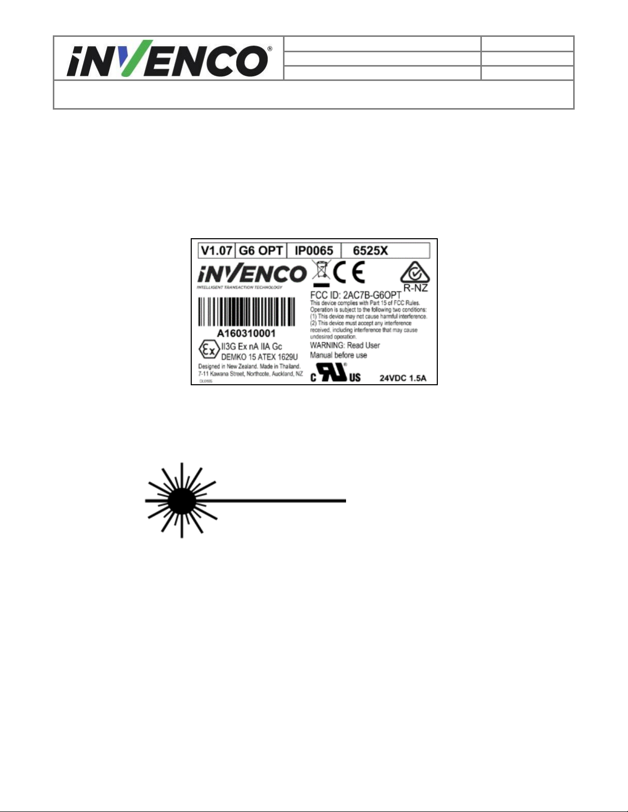
3.1.7 Approvals.........................................................................................................9
3.1.8 Laser Warning .................................................................................................9
3.2 Computer Programs and Documentation................................................................9
4 Disassembly Procedure...............................................................................................10
5 Pre-Installation Procedure............................................................................................40
6 Installation Procedure..................................................................................................41
6.1 Wiring Completion.................................................................................................58
7 First Power-Up.............................................................................................................59

4
Document Number
DCV-00402
Date Released
Jun. 2019
Revision Number/Security level
R02 S2
Retrofit G6+InvencoLink Wayne Vista 3V (US) Installation Guide
1 Introduction
The documentation provides some basic guidelines for installing the Optic 5 / G6 Outdoor Payment
Terminal (OPT).
This Retro-Fit Kit can be installed into either Side A or Side B of a Wayne Vista 3V dispenser;
•For a single-sided installation, or if this Kit will be installed into Side A (i.e. the first side
installed) of a double-sided installation, it requires the pre-installation of UL Listed by Report
Retrofit Kit Part Number 6009-0008-8801 (InvencoLink Converter) before installation into the
dispenser. The process is covered in §4.2 Pre-Installation Procedure of this instruction, by reference
to the instructions in that Kit.
•For a double-sided installation, two of these Kits are required.
1.1 Tools Required
The following tools are required to mount the G6 OPT:
•Torx T25 security screwdriver
•Short Philips #1 screwdriver
•Philips #1 screwdriver with >5” shaft
•Flat 5mm screwdriver
•Small adjustable spanner
•Side cutters
•Cable (zip) ties
•Pliers
•¼” Socket or Nut Driver
•3mm Hex Key
•3” wide jaw Vice Grips
•Standard Vice Grips
•7/32” Socket or Nut Driver
•Flat File
•Disposable drop cloths (eg large
kitchen cloths)
•Magnets
•Neodymium magnets
•Small plastic bag
•Nail polish
•Hacksaw
WARNING
Do NOT use power tools if working on a fuel station
forecourt.
Any spark could cause an explosion.

5
Document Number
DCV-00402
Date Released
Jun. 2019
Revision Number/Security level
R02 S2
Retrofit G6+InvencoLink Wayne Vista 3V (US) Installation Guide
1.2 Installation Kit Contents
Unpack the Retro-Fit Kit and check that all of the parts listed below are present.
G6 OPT, Mounted on RFK Door (MP0551):
PSU plate with cables (EZ0408):
Sheet metal insulating cover assembly (MZ0147)
Hacksaw guide decal (DL0296):
Fastener Kit (FK0013):
Comprising:
4
MS0154 #8-32 x 3/8” machine screws
3
MS0145 8g x 3/8” hex-head screws
1
MF0046 Self-Adhesive, locking cable clip
Cable Kit (IA0031):
Comprising:
EK0137
Ovation Pump to PSU
Adaptor, 1.0m
EK0127
Wayne Pump to InvencoLink,
1.0m
EK0131
Cat-5e, Flexible, 2.5m,
YELLOW
EK0129
Cat-5e, Flexible, 2.5m, RED

6
Document Number
DCV-00402
Date Released
Jun. 2019
Revision Number/Security level
R02 S2
Retrofit G6+InvencoLink Wayne Vista 3V (US) Installation Guide
2 Safety & Compliance Information
This section introduces the hazards and safety precautions associated with installing, inspecting,
maintaining or servicing G6 OPT. Before proceeding, check the relevant hazard and safety information.
Fire, explosion or electrical shock could occur and cause death or serious injury if these safe service
procedures are not followed.
2.1 Preliminary Precautions
You are working in a potentially dangerous environment of flammable fuels, vapour, and high voltage.
Only trained or authorized individuals knowledgeable in the related procedures should install, inspect,
maintain or service this equipment.
2.2 Emergency Total Electrical Shut-Off
Locate the forecourt emergency fuel shut-off valves and electrical isolation breakers. Understand how to
use these, should they be required. Locate the switch or circuit breakers that shut-off all power to all
fuelling equipment and dispensing devices.
2.3 Total Electrical Shut-Off Before Access
Any procedure requiring access to electrical components or the electronics of a pump/dispenser requires
total electrical shut-off of that unit. Understand the function and location of this switch or circuit breaker
before inspecting, installing, maintaining, or servicing the G6/Optic 5 OPT.
2.4 Evacuation, Barricading and Shut-Off
Any procedures requiring accessing a pump/dispenser head requires the following three actions:
•An evacuation of all unauthorized persons and vehicles
•Using safety tape or cones as barricades to the effected units
•A total electrical shut-off of the affected unit(s)
2.5 Read the Manual
Read, understand and follow this manual and any other labels or related materials supplied with the
equipment. If you do not understand a procedure, call an Invenco Authorized Service Centre or Invenco
Service Officer. It is imperative to your safety and the safety of others to understand the procedures
before beginning work.

7
Document Number
DCV-00402
Date Released
Jun. 2019
Revision Number/Security level
R02 S2
Retrofit G6+InvencoLink Wayne Vista 3V (US) Installation Guide
2.6 Follow the Regulations
Regulations in OSHR (Occupational Safety and Health Regulations), national, state and local codes,
including customer requirements must be followed. Failure to install, inspect, maintain or service this
equipment in accordance with these codes, regulations and standards may lead to legal citations with
penalties and may affect the safe use and operation of the equipment.
2.7 Replacement Parts
Use only genuine Invenco replacement parts and retrofit kits on your installation. Using parts other than
genuine Invenco replacement parts could create a safety hazard and violate local regulations.
3 Safety Symbols and Terminology
This safety alert symbol is used in this manual and on warning labels to alert you to a precaution
which must be followed to prevent potential personal safety hazard. Obey safety directives that
follow this symbol to avoid possible injury or death.
Signal Words
These signal words used in this manual and on warning labels tell you the seriousness of particular safety
hazards. The precautions below must be followed to prevent death, injury or damage to the equipment:
DANGER: Alerts you to a hazard or unsafe practice which will result in death or
serious injury.
WARNING: Alerts you to a hazard or unsafe practice that could result in death or
serious injury.
CAUTION: Designates a hazard or unsafe practice which may result in minor
injury, property or equipment damage.
Working With Fuels and Electrical Energy
3.1 Prevent Explosions and Fires
Fuels and their vapors may explode or burn if ignited. Spilled or leaking fuels cause vapors. Even filling
customer tanks will cause potentially explosive vapors in the vicinity of dispenser or island.

8
Document Number
DCV-00402
Date Released
Jun. 2019
Revision Number/Security level
R02 S2
Retrofit G6+InvencoLink Wayne Vista 3V (US) Installation Guide
3.1.1 No Open Flames
Open flames from matches, lighters, welding torches or other sources can ignite fuels and
their vapors.
3.1.2 No Sparks - No Smoking
Sparks from starting vehicles, starting or using power tools, burning cigarettes, cigars or
pipes can also ignite fuels and their vapour. Static electricity, including an electrostatic
charge on your body, can cause a spark sufficient to ignite fuels and their vapors. After
getting out of a vehicle, touch the metal of your vehicle to discharge any electrostatic
charge before you approach the dispenser island.
3.1.3 Working Alone
It is highly recommended that someone who is capable of rendering first aid be present during servicing.
Be familiar with Cardiopulmonary Resuscitation (CPR) methods if you are working with or around high
voltages. This information is available from the First Aid training providers. Always advise the station
personnel about where you will be working, and caution them not to activate power while you are working
on the equipment. Use the OSHA Tag-out/Lockout procedures. If you are not familiar with this
requirement, refer to information in the relevant manual and OSHA documentation.
3.1.4 Working with Electricity Safety
Ensure that you use safe and established practices in working with electrical devices. Poorly wired
devices may cause a fire, explosion or electrical shock. Ensure that grounding connections are properly
made. Take care that sealing devices and compounds are in place. Ensure that you do not pinch wires
when replacing covers. Follow OSHA Tag-out/Lockout requirements. Station employees and service
contractors need to understand and comply with this program completely to ensure safety while
equipment is down.
Follow all applicable requirements in NFPA 30, 30A and 70, and those of the Local Authority Having
Jurisdiction for electrical wiring.
3.1.5 Hazardous Materials
Some materials present inside electronic enclosures may present a health hazard if not handled correctly.
Be sure to clean hands after handling equipment. Do not place any equipment in mouth.
3.1.6 In an Emergency
Compile the following information in case of emergency:
•Location of accident (e.g. address, front/back of building, etc).
•Nature of accident (e.g. possible heart attack, struck by a vehicle, burns, etc).
•Age of victim (e.g. baby, teenager, middle-age, elderly).
•Whether or not victim has received first aid (e.g. stopped bleeding by application of pressure etc).
•Whether or not victim has vomited (e.g. if swallowed or inhaled something etc).

9
Document Number
DCV-00402
Date Released
Jun. 2019
Revision Number/Security level
R02 S2
Retrofit G6+InvencoLink Wayne Vista 3V (US) Installation Guide
IMPORTANT: Oxygen may be needed at scene if gasoline has been ingested or inhaled. Seek medical
advice immediately.
3.1.7 Approvals
Invenco develops and maintains its hardware and software products using industry-standard quality
processes, and is audited by various bodies.
The Invenco G6 OPT has a UL File Reference of MH61528 and carries a label similar to this:
3.1.8 Laser Warning
Some models of the G6 OPT incorporate a barcode reader. The barcode reader incorporates a laser
aiming system. The Laser has a Class 2 output power to IEC 60825-1:2007 / ANSI Z136.1
CAUTION
LASER RADIATION
DO NOT STARE INTO BEAM
1mW MAX OUTPUT at 635-670nm
CLASS 2 LASER PRODUCT4
3.2 Computer Programs and Documentation
All Invenco Group Ltd. computer programs (including software on discs and within memory chips) and
documentation are copyrighted by, and shall remain the property of, Invenco Group Ltd. Such computer
programs and documents may also contain trade secret information. The duplication, disclosure,
modification, or unauthorized use of computer programs or documentation is strictly prohibited, unless
otherwise licensed by Invenco Group Ltd.

10
Document Number
DCV-00402
Date Released
Jun. 2019
Revision Number/Security level
R02 S2
Retrofit G6+InvencoLink Wayne Vista 3V (US) Installation Guide
4 Disassembly Procedure
PRECAUTION:
•Please ensure all safety procedures are followed per requirement by the customer before
installing the retrofit kit.
•Remove power to Pump and follow the OSHA Lock-out/Tag-out procedures.
•This installation will require a panel replacement. The panel will be removed from the door and
replaced with a pre-built panel with the OPT pre-fitted.
Before installation of the equipment can take place, the existing electronic payment assembly
must be removed from the dispenser. This section covers the removal of these components
including:
•The Wayne Graphic Display Assembly
•The Printer
•The Printer Bracket
•The Water Catch Tray
•The Q-CAT Board (or the dual CAT board)
•Various Cable Assemblies
1. At the main disconnect panel, disconnect all power to the dispenser and the pump servicing the
dispenser. Tag all disconnected breakers to prevent others from reconnecting power.
2. Identify the Side A of the dispenser.
Note: For the purposes of this manual, Side A of the dispenser refers to the side with the
manufacturer’s label/Serial Number Plate.
3. Identify whether the pump is a “Wide Frame” or “Narrow Frame” version from the pictures below –
some steps below vary depending which version you have:
Use a Wayne Security Key to unscrew the two security bolts at the top left and top right of the
electronics head bezel. (Fig. 4.3)
Failure to turn off the unit during installation of the kit may cause injury or bodily harm from electrical shock.
Ensure that all power to the unit is switched off before opening the door of the unit and during kit installation.
WARNING

11
Document Number
DCV-00402
Date Released
Jun. 2019
Revision Number/Security level
R02 S2
Retrofit G6+InvencoLink Wayne Vista 3V (US) Installation Guide
Fig. 4.3 –Wide Frame (top) - Side A of Electronics Bezel - Narrow Frame (bottom)
4. Lower the electronics head bezel by pulling the top forward until it fully rests on the suspension
cables.
5. Locate the Graphic Display Assembly or Single Line Display (Fig 4.5):
Security Bolts

12
Document Number
DCV-00402
Date Released
Jun. 2019
Revision Number/Security level
R02 S2
Retrofit G6+InvencoLink Wayne Vista 3V (US) Installation Guide
Fig. 4.5 –Electronics Bezel in fully lowered position
6. For the Graphic Display Assembly:
Unplug the 8-pin display cable and the two-wire ribbon cable that are connected to the Graphic
Display Assembly (Fig 4.6):
Graphics
Display
Assembly
Single Line
Display
Assembly

13
Document Number
DCV-00402
Date Released
Jun. 2019
Revision Number/Security level
R02 S2
Retrofit G6+InvencoLink Wayne Vista 3V (US) Installation Guide
Fig. 4.6 –Location of both Graphics Display cables that will need unplugged
7. For the Single Line Display:
Unplug the 40-pin display cable and the two-wire grey cable that are connected to the Single Line
Display Assembly (Fig 4.7):
Fig 4.7 –Location of both Single Line Display cables that will need unplugged
Two-Wire
Ribbon Cable
8-pin Display
Cable
40-pin
Display
Cable
Two-Wire
Grey Cable

14
Document Number
DCV-00402
Date Released
Jun. 2019
Revision Number/Security level
R02 S2
Retrofit G6+InvencoLink Wayne Vista 3V (US) Installation Guide
The remaining cables are attached to peripheral components that will be removed along with the
Display Assembly later in the disassembly process.
8. For the Graphic Display Assembly:
Locate and remove the (3) ¼” head mounting screws located along the bottom of the Graphic
Display Assembly. (Fig 4.8a)
Fig. 4.8a –Location of the 3 screws that need removal
Note: There may be a variant design for the Card Reader Rain Catcher. The process for
removing the Graphic Display Assembly is identical to the one in Step 8, with the
exception that the rain catch has TWO screws fastening it instead of ONE. However,
only one of these screws will need to be removed. A 5” long screwdriver will be
needed to reach the screw. Use Fig 4.8b as a visual guide.
Mounting Screws
(One located below card reader)

15
Document Number
DCV-00402
Date Released
Jun. 2019
Revision Number/Security level
R02 S2
Retrofit G6+InvencoLink Wayne Vista 3V (US) Installation Guide
Fig. 4.8b –Location of the screw that needs removal
9. Remove the ¼” head ground strap screw from the earth plate on the dispenser door. Retain the
screw for later use:
Fig. 4.9 –Location of the ground strap screw
10.Remove the Display Assembly from the electronics head bezel by lifting the bottom of it up and
out. Set the assembly aside to be discarded. (Fig 4.10b)
Note: For Narrow Frame Dispensers, you may need to remove one of the Totalizer Window
screws in order to make clearance when removing the Display Assembly. Remove this
screw and retain it. It will be re-installed later during the Installation Procedure. (Fig
4.10a)
This screw may
remain in place
Remove this
screw
Variant
rain catcher
Remove this
screw

16
Document Number
DCV-00402
Date Released
Jun. 2019
Revision Number/Security level
R02 S2
Retrofit G6+InvencoLink Wayne Vista 3V (US) Installation Guide
Fig. 4.10a –Remove Totalizer Window Screw (Narrow Frame only)
Fig. 4.10b –Grab the card reader and remove the assembly
Remove and retain
this screw

17
Document Number
DCV-00402
Date Released
Jun. 2019
Revision Number/Security level
R02 S2
Retrofit G6+InvencoLink Wayne Vista 3V (US) Installation Guide
11.Remove the Q-CAT boards or Dual CAT board if present.
11.1 Q-CAT boards
a) Identify and locate the Q-CAT boards. It is fitted on the right-hand side wall per each side. If not
present, follow procedures for removing the Dual CAT board instead (step 11.2).
Fig. 4.11.1a –Location of the Q-CAT board
b) Disconnect any cables connected to the Q-CAT Board. The Purple/Brown cable is used for
communications. It must be marked and retained for later use.
Fig. 4.11.1b –Location of the Q-CAT board

18
Document Number
DCV-00402
Date Released
Jun. 2019
Revision Number/Security level
R02 S2
Retrofit G6+InvencoLink Wayne Vista 3V (US) Installation Guide
c) This board is attached by 6 Philips head screws. Undo the screws and remove and discard the
Board.
d) Fig. 4.11.1c –Remove the screws

19
Document Number
DCV-00402
Date Released
Jun. 2019
Revision Number/Security level
R02 S2
Retrofit G6+InvencoLink Wayne Vista 3V (US) Installation Guide
11.2 Dual CAT board
a) Identify and locate the Dual CAT board. It is fitted on the printer mounting bracket.
Fig. 4.11.2a –Location of the Dual-CAT board
b) Disconnect any cables connected to the dual-CAT Board. The Purple/Brown cable is used for
communications. It must be marked and retained for later use.
Fig. 4.11.2b –Disconnect and retain the purple/brown cable
Table of contents
Other NCR Network Hardware manuals
Popular Network Hardware manuals by other brands

QNAP
QNAP TS 83XU Series user guide

Elspec
Elspec G4500 Series Quick reference guide

Buffalo
Buffalo WLA2-G54 Quick setup guide

Atlantis Land
Atlantis Land DiskMaster NAS G303S manual

LaCie
LaCie 4big Rack Office Quick install guide

Matrix Switch Corporation
Matrix Switch Corporation MSC-HD44DES product manual