Emerson Network Power NetSure 501 A41-S1 User manual

NetSure 701 A41, NetSure 501 A41, NetSure 501 A91
Subrack Power system User Manual
Version V1.0
Revision date August 29, 2012
BOM 31012653
Emerson Network Power provides customers with technical support. Users may contact the nearest
Emerson local sales office or service center.
Copyright © 2012 by Emerson Network Power Co., Ltd.
All rights reserved. The contents in this document are subject to change without notice.
Emerson Network Power Co., Ltd.
Address: No.1 Kefa Rd., Science & Industry Park, Nanshan District 518057, Shenzhen China
Homepage: www.emersonnetworkpower.com.cn
E-mail: support@emersonnetwork.com.cn

Safety Precautions
To reduce the chance of accident, please read the safety precautions very carefully before operation. The
"Caution, Notice, Warning, Danger" in this book do not represent all the safety points to be observed, and are
only supplement to various safety points. Therefore, the installation and operation personnel must be strictly
trained and master the correct operations and all the safety points before actual operation.
When operating Emerson products, the safety rules in the industry, the general safety points and special safety
instructions specified in this book must be strictly observed.
Electrical Safety
I. Hazardous voltage
Danger
Some components of the power system carry hazardous voltage in operation. Direct contact or indirect contact through
moist objects with these components will result in fatal injury.
Safety rules in the industry must be observed when installing the power system. The installation personnel must
be licensed to operate high voltage and AC power.
In operation, the installation personnel are not allowed to wear conductive objects such as watches, bracelets,
bangles, rings.
When water or moisture is found on the Subrack, turn off the power immediately. In moist environment,
precautions must be taken to keep moisture out of the power system.
"Prohibit" warning label must be attached to the switches and buttons that are not permitted to operate during
installation.
Danger
High voltage operation may cause fire and electric shock. The connection and wiring of AC cables must be in compliance
with the local rules and regulations. Only those who are licensed to operate high voltage and AC power can perform high
voltage operations.
II. Tools
Warning
In high voltage and AC operation, special tools must be used. No common or self-carried tools should be used.
III. Thunderstorm
Danger
Never operate on high voltage, AC, iron tower or mast in the thunderstorm.
In thunderstorms, a strong electromagnetic field will be generated in the air. Therefore the equipment should be
well earthed in time to avoid damage by lightning strikes.

IV. ESD
Notice
The static electricity generated by the human body will damage the static sensitive elements on PCBs, such as large-scale
ICs. Before touching any plug-in board, PCB or IC chip, ESD wrist strap must be worn to prevent body static from
damaging the sensitive components. The other end of the ESD wrist strap must be well earthed.
V. Short circuit
Danger
During operation, never short the positive and negative poles of the DC distribution unit of the system or the non-grounding
pole and the earth. The power system is a constant voltage DC power equipment, short circuit will result in equipment
burning and endanger human safety.
Check carefully the polarity of the cable and connection terminal when performing DC live operations.
As the operation space in the DC distribution unit is very tight, please carefully select the operation space.
Never wear a watch, bracelet, bangle, ring, or other conductive objects during operation.
Insulated tools must be used.
In live operation, keep the arm muscle tense, so that when tool connection is loosened, the free movement of
the human body and tool is reduced to a minimum.
VI. Dangerous energy
Warning
240VA, hazardous energy, keep off, no bridge connection. This converter contains outputs exceed 240VA, when installing
into end system care must be taken that the output and appropriate wire may not be touched.
Battery
Danger
Before any operation on battery, read carefully the safety precautions for battery transportation and the correct battery
connection method.
Non-standard operation on the battery will cause danger. In operation, precautions should be taken to prevent
battery short circuit and overflow of electrolyte. The overflow of electrolyte will erode the metal objects and PCBs,
thus causing equipment damage and short circuit of PCBs.
Before any operation on battery, pay attention to the following points:
Remove the watch, bracelet, bangle, ring, and other metal objects on the wrist.
Use special insulated tools.
Use eye protection device, and take preventive measures.
Wear rubber gloves and apron to guard against electrolyte overflow.
In battery transportation, the electrode of the battery should always be kept facing upward. Never put the battery
upside down or slanted.

BLVD
The system has battery low voltage disconnection (BLVD) function. BLVD means when the mains fail and
batteries supply power, the monitoring module cuts the load off when the battery voltage drops down to below
43.2V to prevent over-discharge. The BLVD voltage is settable. Refer to 4.2.3 Battery Selection for setting
method.
The factory setting is enabling BLVD, which means that if power outage lasts for a long time or the power system
fails, there might be BLVD. Users should classify the loads and connect the priority loads to BLVD routes. For
vital loads, users can disable BLVD of these loads to insure reliability of the power supply.
The method of disabling BLVD is:
Set “BLVD Enable” item of the monitoring module to “N”. Refer to 4.2.3
错误
错误错误
错误!
!!
!未找到引用源
未找到引用源未找到引用源
未找到引用源。
。。
。
for setting
method.
Notice
The advantage of enabling BLVD is protecting the batteries from over-discharge when the battery voltage is low. The
disadvantage of enabling BLVD is that when the battery voltage drops down to a certain value, all the loads (including
non-priority loads and priority loads) will be cut off due to battery disconnection.
The advantage of software disabling BLVD is prolonging the power supply of priority loads. The disadvantage is that
software disabling cannot prevent unwanted power failure due to misoperation or power system failure.
Others
I. Sharp object
Warning
When moving equipment by hand, protective gloves should be worn to avoid injury by sharp object.
II. Cable connection
Notice
Please verify the compliance of the cable and cable label with the actual installation prior to cable connection.
III. Binding the signal lines
Notice
The signal lines should be bound separately from heavy current and high voltage lines, with binding interval of at least
150mm.

Contents
Chapter 1 Overview ............................................................................................................................................................1
1.1 Model Information.................................................................................................................................................1
1.2 Composition And Configuration............................................................................................................................1
1.3 Features................................................................................................................................................................4
Chapter 2 Installation Instruction.........................................................................................................................................5
2.1 Safety Regulations................................................................................................................................................5
2.2 Preparation...........................................................................................................................................................5
2.3 Mechanical Installation..........................................................................................................................................6
2.4 Electrical Installation.............................................................................................................................................9
2.4.1 Power System Cabling Method .................................................................................................................9
2.4.2 Connecting AC Input Cables ...................................................................................................................10
2.4.3 Connecting Load Cables .........................................................................................................................11
2.4.4 Connecting Battery Cables......................................................................................................................11
2.4.5 Connecting Signal Cables .......................................................................................................................12
Chapter 3 Installation Testing............................................................................................................................................16
3.1 Installation Check And Startup............................................................................................................................16
3.2 Basic Settings.....................................................................................................................................................16
3.3 Alarm Check And System Operation Status Check............................................................................................17
3.4 Final Steps..........................................................................................................................................................18
Chapter 4 Use Of Monitoring Module M221S、M221S.....................................................................................................19
4.1 Control Keypad And Indicator.............................................................................................................................19
4.1.1 Front Panel..............................................................................................................................................19
4.1.2 Indicator Function....................................................................................................................................19
4.1.3 Control Keypad Function.........................................................................................................................19
4.2 LCD Menu Tree ..................................................................................................................................................20
4.2.1 Status ......................................................................................................................................................20
4.2.2 Settings....................................................................................................................................................21
4.2.3 Manual.....................................................................................................................................................28
4.2.4 ECO.........................................................................................................................................................28
4.2.5 Quick Setting...........................................................................................................................................28
4.2.6 Controller Setting.....................................................................................................................................29
4.3 WEB Interface Operation....................................................................................................................................30
4.3.1 Setting Up The Internet Explorer Web Browser.......................................................................................30
4.3.2 Logging Into The Controller.....................................................................................................................31
4.3.3 Homepage Introduction ...........................................................................................................................32
4.4 WEB Bootloader Interface Operation..................................................................................................................36
4.5 Serial Bootloader Interface Operation.................................................................................................................37

Chapter 5 Use Of Monitoring Module M820B....................................................................................................................41
5.1 Operation Panel..................................................................................................................................................41
5.2 First Screen.........................................................................................................................................................42
5.3 Default Main Screen ...........................................................................................................................................42
5.4 Overall Menu Structure.......................................................................................................................................43
5.5 Main Menu..........................................................................................................................................................43
5.6 Status..................................................................................................................................................................44
5.7 Manual................................................................................................................................................................46
5.7.1 Settings....................................................................................................................................................47
5.7.2 Power System Setting .............................................................................................................................55
5.7.3 Rectifier Setting.......................................................................................................................................57
5.7.4 Battery Setting.........................................................................................................................................57
5.7.5 Parameter Settings Of BattFuseUnit .......................................................................................................59
5.7.6 Parameter Settings Of DC.......................................................................................................................59
5.7.7 Parameter Setting Of LVD.......................................................................................................................59
5.7.8 AC Parameter Settings............................................................................................................................60
5.7.9 Communication Parameter Settings........................................................................................................60
5.7.10 Controller Parameter Settings ...............................................................................................................60
5.8 Energy Saving Setting ........................................................................................................................................60
5.9 Quick Settings.....................................................................................................................................................61
5.10 Access M820B Through Web...........................................................................................................................61
5.10.1 Login......................................................................................................................................................62
5.10.2 Homepage Introduction .........................................................................................................................63
5.10.3 Device Information.................................................................................................................................64
5.10.4 Data Browse, Control And Parameter Setting Of Rectifier.....................................................................64
5.10.5 Data Browse, Control And Parameter Setting Of Battery ......................................................................67
5.10.6 Alarms ...................................................................................................................................................69
5.10.7 Maintenance..........................................................................................................................................70
5.10.8 Configurations .......................................................................................................................................78
5.10.9 Query.....................................................................................................................................................83
5.11 Access ACU+ Through NMS ............................................................................................................................85
5.11.1 NMS Supported By SNMP Agent..........................................................................................................85
5.11.2 MIB Installation......................................................................................................................................85
5.11.3 Access ACU+ Through NMS.................................................................................................................86
5.11.4 ESR Configure.......................................................................................................................................87
Chapter 6 Alarm Handling.................................................................................................................................................88
6.1 Handling Alarms..................................................................................................................................................88
6.2 Handling Rectifier Fault.......................................................................................................................................89

Appendix 1 Technical And Engineering Data....................................................................................................................91
Appendix 2 Installation Instruction Of Battery Rack ..........................................................................................................95
1. Installation Instruction Of Two-Layer And Four-Layer Battery Rack.....................................................................95
2. Installation Instruction Of Three-Layer Battery Rack.............................................................................................97
3. Fixing The Battery Rack........................................................................................................................................98
Appendix 3 Wiring Diagram...............................................................................................................................................99
Appendix 4 Shematic Diagram........................................................................................................................................107
Appendix 5 Glossary.......................................................................................................................................................115


Chapter 1 Overview 1
NetSure 701 A41, NetSure 501 A41, NetSure 501 A91 Subrack Power system User Manual
Chapter 1 Overview
This chapter introduces model description, composition and configuration, and features.
The “power system” in this manual refers to the NetSure NetSure 701 A41, NetSure 501 A41, NetSure 501 A91
series 19 subrack power system.
1.1 Model Information
Take NetSure 501 A41-S1 power system as an example, the model description is given in Figure 1-1.
NetSure 501 A 4
Region. A: Asia-Pacific region
Output power of the rectifier. 501: 1740W ~2000W. 701: 2900W ~5000W
rand name of the power supply system
1
Version
The number of the rectifier in the typical power supply system: 4. If the number ranges between 0 ~ 9,
the character is represented by a number. If the number is larger than 9, the character isrepresented
by a letter, for example, A represents the number 10, represents the number 11,and so on
S 1
Cabinet type: Subrack
Cabinet configuration
Figure 1-1Model information
1.2 Composition And Configuration
System composition
The system consists of power distribution parts, rectifiers and monitoring module. The rectifier model is
R48-1800, R48-2900U or R48-3200 and the model of the monitoring module is M221S, M222S or M820B. The
internal structures of the systems are shown in Figure 1-2 to Figure 1-6.
Figure 1-2 NetSure 501A41- S1/S2 system structure

2 Chapter 1 Overview
NetSure 701 A41, NetSure 501 A41, NetSure 501 A91 Subrack Power system User Manual
Dummy panel
Load MC
Rectifier
Monitoring module
attery MC
Positive terminals
Controller
AC input MC
Figure 1-3 NetSure 501A91-S1 system structure
Figure 1-4 NetSure 701A41 –S2/S4 system structure
Figure 1-5 NetSure 701A41-S1/S3/S5 system structure
Figure 1-6 NetSure 701A41-S5 system structure
System configuration
The configurations of the power system are described in Table 1-1.

Chapter 1 Overview 3
NetSure 701 A41, NetSure 501 A41, NetSure 501 A91 Subrack Power system User Manual
Table 1-1 Configuration of fixed- configuration system
Item NetSure 501 A41-S1
NetSure 501 A41-S2
NetSure 501 A91-S1
NetSure 701 A41-S1
NetSure 701 A41-S2
NetSure 701 A41-S3
NetSure 701 A41-S4
NetSure 701 A41-S5
Contorller Model:
M221S/M222S Model:
M820B Model:
M221S/M222S Model:
M221S/M222S Model:
M221S/M222S Model:
M221S/M222S Model:
M820B Model:
M221S/M222S
Rectifier
Model:
R48-1800A/R48-2000/
R48-2000e
Standard
configuration:
4 pieces
Model:
R48-1800A/R48-2000/
R48-2000e
Standard
configuration:4 pieces
Model:
R48-1800A/R48-2000
/R48-2000e
Standard
configuration:5
pieces
Model:
R48-2900U/R48-300
0e/R48-3200/R48-35
00e/R48-4000e
Standard
configuration:3
pieces
Model:
R48-2900U/
R48-3000e
R48- 3200
R48-3500e
R48-4000e
Standard
configuration:4
pieces
Model:
R48-2900U/
R48-3000e
R48- 3200
R48-3500e
R48-4000e
Standard
configuration:4
pieces
Model:
R48-2900U/
R48-3000e
R48- 3200
R48-3500e
R48-4000e
Standard
configuration:4
pieces
Model:
R48-2900U/
R48-3000e
R48- 3200
R48-3500e
R48-4000e
Standard
configuration:4个
AC power
distribution L+N+PE/ 220Vac L+N+PE/220Vac 3P+N+PE/380Vac
3P+N+PE/380Vac
L+N+PE/380Vac 3P+N+PE/ 220Vac
3P+N+PE/ 380Vac
L+N+PE/ 220Vac
DC power
distribution
BLVD load route:
2 × 16A/1P,
MCB
LLVD load route:
2 × 63A/1P,
2 × 32A/1P
MCB
BLVD load route:
2 × 10A/1P,
2 × 32A/1PMCB
LLVD load route:
2 × 63A/1P,
2 × 32A/1P
MCB
BLVD load route:
5 × 63A/1P,
5 × 32A/1P,
8 × 10A/1P
MCB
LLVD load route:
Not configured
BLVD load route:
1 × 10A/1P
MCB
LLVD load route:
4 × 40A/1P
MCB
BLVD load route:
4 × 63A/1P,
6 × 32A/1P,
2 × 10A/1P
MCB
LLVD load route:
Not configured
BLVD load route:
2 × 32A/1P,
2 × 16A/1P
MCB
LLVD load route:
2×63A/1P,
4×32A/1P,
2×16A/1P MCB
BLVD load route:
2 × 63A/1P
4 × 32A/1P,
4 × 10A/1P
MCB
LLVD load route:
2×100A/1P
2×63A/1P,
2×32A/1P MCB
BLVD load route:
2 × 32A/1P,
2 × 16A/1P
MCB
LLVD load route:
2×63A/1P, 4×
32A/1P MCB
Battery MCB 2 × 63A/1P 2 × 125A/1P 2 × 125A/1P 2 × 125A/1P 2 × 125A/1P 2 × 125A/1P 2 × 125A/1P 2 × 125A/1P
AC SPD 1 piece Optional Optional Optional Optional 1 piece
Optional 1 piece
DC SPD 1 piece Optional Optional Optional Optional 1 piece
Optional 1 piece
Max.size (mm) 483 × 360 × 222 483 × 360 × 222 483 × 360 × 400 483 × 360 × 267 483 × 360 × 267 483 × 360 × 267 483 × 360 × 400 483 × 360 × 267
BLVD contorller
mode Contorller power-off Contorller power-on Contorller power-on Contorller power-on Contorller power-on Contorller power-off Contorller power-on Contorller power-off
Weight ≤25kg ≤25kg ≤25kg ≤25kg ≤25kg ≤25kg ≤25kg ≤25kg
Notes:
1. Temperature sensor and connected cables, remote monitoring unit, battery rack.
2. The way of outage for control is cutting off the battery, disconnecting the monitor and storage battery, monitor dropping out and communication broken up.

4 Chapter 1 Overview
NetSure 701 A41, NetSure 501 A41, NetSure 501 A91 Subrack Power system User Manual
1.3 Features
The rectifier uses the active Power Factor Compensation (PFC) technology, raising the power factor to 0.99.
Wide AC input voltage range: 85V ~ 290V (NetSure 701 A41) or 85Vac ~ 300Vac (NetSure 501 A41 & NetSure
501 A91).
The rectifier uses soft switching technology, raising the system rated efficiency to 91%, and the efficient systems
can be as high as 95%.
Ultra-low radiation. With advanced EMC design, the rectifier meets international standards such as CE and
NEBS. Both the conducted and radiated interference reach Class B.
The rectifier safety design complies with UL, CE and NEBS standards.
High power density.
Rectifiers are hot pluggable. It takes less than 1min to replace a rectifier.
Two over-voltage protection methods are optional: hardware protection and software protection. The latter one
also has two optional modes: lock-out at the first over-voltage and lock-out at the second over-voltage.
Perfect battery management: The management functions include the LLVD (optional), BLVD, temperature
compensation, auto voltage regulation, stepless current limiting, battery capacity calculation and on-line battery
test, etc.
M221S and M222S support historical alarm record up to 200 and historical record up to 1000. And M820B
supports historical alarm record up to 3000 and historical record up to 60000
10 sets of battery test data records.
Network design: Providing multiple communication ports (such as RS232, modem and dry contacts), which
enables flexible networking and remote monitoring. M820B support the USB communication interface.
Perfect lightning protection at AC side and DC side.
Complete fault protection and fault alarm functions.
NetSure 701 A41-S3, NetSure 701 A41-S5 and NetSure 501A41-S1 adopt the way of outage for control, This
way effectively prevents the storage battery from deeply discharging after system battery protection drops out
and hence prevents the unattended outdoors and indoors server rooms from the damage due to the deep
discharge.

Chapter 2 Installation Instruction 5
NetSure 701 A41, NetSure 501 A41, NetSure 501 A91 Subrack Power system User Manual
Chapter 2 Installation Instruction
2.1 Safety Regulations
Certain components in this power system have hazardous voltage and current. Always follow the instructions below:
1. Only the adequately trained personnel with satisfactory knowledge of the power system can carry out the
installation. The most recent revision of these safety rules and local safety rules in force shall be adhered to during
the installation.
2. All external circuits that are below 48V and connected to the power system must comply with the requirements of
SELV as defined in IEC 60950.
3. Make sure that the power (mains and battery) to the system is cut off before any operations can be carried out
within the system subrack.
4. The power subracks shall be kept locked and placed in a locked room. The key keeper should be the one
responsible for the power system.
5. The wiring of the power distribution cables should be arranged carefully so that the cables are kept away from the
maintenance personnel.
2.2 Preparation
Unpacking inspection
The equipment should be unpacked and inspected after it arrives at the installation site. The inspection shall be done
by representatives of both the user and Emerson Network Power Co., Ltd.To inspect the equipment, you should open
the packing case, take out the packing list and check against the packing list that the equipment is correct and
complete. Make sure that the equipment is delivered intact.
Cables
The cable design should meet relevant industry standards.
It is recommended to use the RVVZ cables as AC cables. The cable should reach at least +70°C temperature
durability. With cable length shorter than 30 meters, the Cross-Sectional Area (CSA) calculation should be based on
the current density of 3.5A/mm
2
. The suggested CSA value is no less than the Table 2-1.
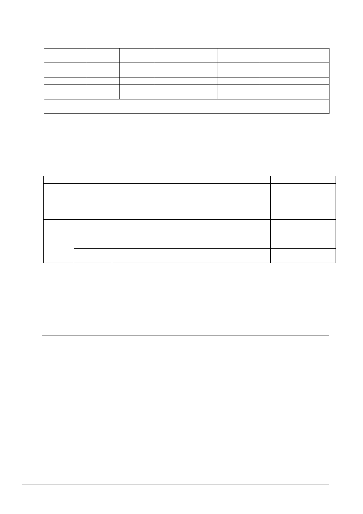
Table 2-1 Load cable CSA selection
AC MCB rated current Max. battery current Min. cable CSA Max. cable length
125A 105A 35mm
2
50mm
2
100A 80A 25mm
2
50mm
2
63A 50A 16mm
2
25mm
2
The CSA of DC cable depends on the current flowing through the cable and the allowable voltage drop. To select the
battery cable CSA, see Table 2-2. Select the DC load cable CSA according to the Table 2-3.
Table 2-2 Battery cable CSA selection
Battery MCB rated current
Max. battery current
Min. cable CSA
Max. cable length (volt drop: 0.5V, with max. CSA)
125A 105A 35mm
2
6 m
63A 50A 16 mm
2
5 m
Note:
1. The specs are applicable at ambient temperature of 25°C. If the temperature is higher or lower than this, the CSA of the cable
should be increased.
2. The battery cable should reach at least +90°C heat durability. It is recommended to use double-insulated copper-core flame
retardant cable as battery cable
6 Chapter 2 Installation Instruction
NetSure 701 A41, NetSure 501 A41, NetSure 501 A91 Subrack Power system User Manual
Table 2-3 DC load cable selection
Load route rated
current Max. output
current Min. cable
CSA Max. cable length (volt
drop:
0.5V, with min. CSA) Max. cable CSA
Max. cable length (volt drop:
0.5V, with max. CSA)
100A 80A 25mm
2
14m 50mm
2
20m
63A 50A 16mm
2
9m 25mm
2
14m
32A 25A 10mm
2
11m 25mm
2
29m
16A 12A 6mm
2
14m 25mm
2
48m
10A 8A 6mm
2
23m 25mm
2
98m
Note: The specs are applicable at ambient temperature of 25°C. If the temperature is higher than this, the CSA of the cable should
be increased
To prevent the air switching capacity is too large, the load overload does not work. Recommended the capacity of the
air switching is up to 1.5 ~ 2 times of the load peak.
The CSA of the system grounding cables should be consistent with the largest power distribution cables. The CSA
value is no less than 25mm
2
.
AC and DC power distribution interface definition see Table 2-4.
Table 2-4 AC and DC power distribution interface definition
Connector name Connector specifications Wiring instructions
AC power
distribution
AC input MCB
H type terminal, max. cable CSA 35mm
2
(Single-phase power input)
H type terminal, max. cable CSA 25mm
2
(Three -phase power input) AC power line
Grounding
busbar One M8 bolt, OT type wiring terminal, max. cable CSA 35mm
2
Connected to the
grounding bar of the
equipment room
DC power
distribution
Battery output
MCB H type terminal, max. cable CSA 25mm
2
(63A and below)
H type terminal, max. cable CSA 50mm
2
(capacity above 63A) Connected to the battery
port
Negative
output MCB H type terminal, max. cable CSA 25mm
2
(63A and below)
H type terminal, max. cable CSA 50mm
2
(capacity above 63A) Connected to the users load
port
Positive
busbar Terminal subrack terminal:cable CSA ≤50mm
2
Connected to the users load
port
2.3 Mechanical Installation
Note
1. The cabinet or rack the subrack power supply system installed in must provide fireproof and electric protection casing, or
install in cement or other difficult to burn, at the same time and other combustible materials to keep enough distance.
2. For the convenience of maintenance, users should maintain a clearance of 800mm at the front of the power supply system.
3. Subrack cannot be installed against the wall, it must leave enough space for heat dissipation.
Installed on battery bracket
1. Fix the subrack power system to the battery bracket through the connectors with M6 bolts, as shown in Figure 2-1.

Chapter 2 Installation Instruction 7
NetSure 701 A41, NetSure 501 A41, NetSure 501 A91 Subrack Power system User Manual
M6 screw
Connector
Subrack
power system
attery
bracket
M6 screw
Connector
Figure 2-1 Cabinet and rack installation
Installed in cabient
Insert the subrack power system to the matching cabinet, as shown in Figure 2-2.
电源插框
Subrack power
system
Figure 2-2 Installed in the cabinet system
The engineering graphics of the s
ubrack
power system as shown in Figure 2-3 to Figure 2-8.

8 Chapter 2 Installation Instruction
NetSure 701 A41, NetSure 501 A41, NetSure 501 A91 Subrack Power system User Manual
Figure 2-3 Installation size of NetSure 501 A41 (unit: mm)
445
Figure 2-4 Installation size of NetSure 501 A91 (unit: mm)
Figure 2-5 Installation size of NetSure 701 A41-S1 (unit: mm)
Figure 2-6 Installation size of NetSure 701 A41-S2/S3 (unit: mm)

Chapter 2 Installation Instruction 9
NetSure 701 A41, NetSure 501 A41, NetSure 501 A91 Subrack Power system User Manual
Figure 2-7 Installation size of NetSure 701 A41- S4 (unit: mm)
265.0
438.5
482
.
6
Figure 2-8 Installation size of NetSure 701 A41-S5 (unit: mm)
Note
1. Tighten the captive screw of the MFU and DU Panel by the cross head screwdriver when there is no operation.
2. Also tighten the handle of the 501 modules by the cross head screwdriver.
3. Please plug in the new modules or installing a new panel after removing the rectifier module.
2.4 Electrical Installation
2.4.1 Power System Cabling Method
Cabling from the top of the power system
DU unit and MFU unit are available for the system top cover cabling.
For DU unit cabling: Cabling from the cable outlet area and then fixed to the cable-bundling plate and the top edge.
As shown in Figure 2-9.

10 Chapter 2 Installation Instruction
NetSure 701 A41, NetSure 501 A41, NetSure 501 A91 Subrack Power system User Manual
Cable outlet area
Cable-bundling plate
Cable outlet area
Figure 2-9 Cable entry Illustration of the DU unit
The MFU unit cabling is shown in 2-10.
Figure 2-10 Cable entry Illustration of the MFU unit
Cabling from side of the power system
Use a cross head screwdriver to remove two screws which fix the cabling panel at side of cabling area, then the cable
can be led out from the cabling area, as shown in Figure 2-11.
出线板
(出线空间
)
螺钉
Figure 2-11 Side cable cabling Illustration
2.4.2 Connecting AC Input Cables
Danger
1. Switch off all MCBs before the electrical connection.
2. Only the qualified personnel can do the mains cable connection.
Take the NetSure 701 A41 power supply system as an example, the position of the terminals are shown in
Figure 2-12.

Chapter 2 Installation Instruction 11
NetSure 701 A41, NetSure 501 A41, NetSure 501 A91 Subrack Power system User Manual
Figure 2-12 Illustration of the connection terminal
注意
注意注意
注意
若用户选用插框的交流输入采用的是端子形式,无过流和短路保护功能,则需要在插框前级配过流和接地保护器件,具
体保护器件规格的选择可以咨询艾默生网络能源有限公司当地的技术支持。
2.4.3 Connecting Load Cables
Connect the negative cable of the load to the upper terminal of load MCB. Connect the positive cable of the load to
the DC positive busbar, as shown in Figure 2-13.
Figure 2-13 Illustration of the load cable connection terminal
2.4.4 Connecting Battery Cables
Note
1. The batteries may have dangerous current. Before connecting the battery cables, the corresponding battery input MCBs or the
battery cell connector must be disconnected to avoid live state of the power system after installation.
2. Be careful not to reverse connect the battery. Otherwise, both the battery and the power system will be damaged!
1. Connect one end of the negative battery cable to the upper terminal of battery MCBs. Connect one end of the
positive battery cable to the DC positive bus bar.
2. Connect copper lugs to the other end of the battery cables. Bind the connecting parts with insulating tape, and put
them beside the battery. Connect the cables to the battery when the DC distribution unit is to be tested. As shown in
Figure 2-14.
attery MC
Positive terminal
Figure 2-14 Illustration of the battery connection terminal

12 Chapter 2 Installation Instruction
NetSure 701 A41, NetSure 501 A41, NetSure 501 A91 Subrack Power system User Manual
2.4.5 Connecting Signal Cables
There are two user interface board of the power system can optional, respectively the W2453X1 user interface board
and IB2 user interface board. The W2453X1 user interface board is used together with the M221S monitoring unit or
M222S monitoring unit only; and the IB2 user interface board is used together with the M820B monitoring unit only.
W2453X1 user interface board cable connection
Take the NetSure 501 A41 power supply system as an example, the position of the user connector board (W2453X1)
is shown in Figure 2-15.
Figure 2-15 W2453X1 user interface board Illustration
At most two user connector boards are allowed in the power supply system. Standard cabinet is only configured with
one user connector board.
With one user connector board configured, the power supply system provides three external digital signal input
interfaces: DI2, DI3, DI4 (DI1 is used for DC SPD alarm. If no DC SPD is configured in the power supply system, DI1
is available) and four dry contact alarm output interfaces: DO1, DO2, DO3, DO4. With two user connector boards
configured, the power supply system provides additional four dry contact alarm output interfaces: DO5, DO6, DO7,
and DO8.
This manual suits for next models
7
Table of contents
Popular Power Supply manuals by other brands


Gallagher
Gallagher M700 instructions

Skyrc
Skyrc eFuel 1200WATTS instruction manual

Stanford Research Systems
Stanford Research Systems PS355 Operation and service manual

LEGRAND
LEGRAND WIREMOLD 1022306R2 0119 installation instructions

Nemtek
Nemtek MERLIN 4 Installer manual

Daintree
Daintree GE current Tetra GEPS24-100U-GLX installation guide