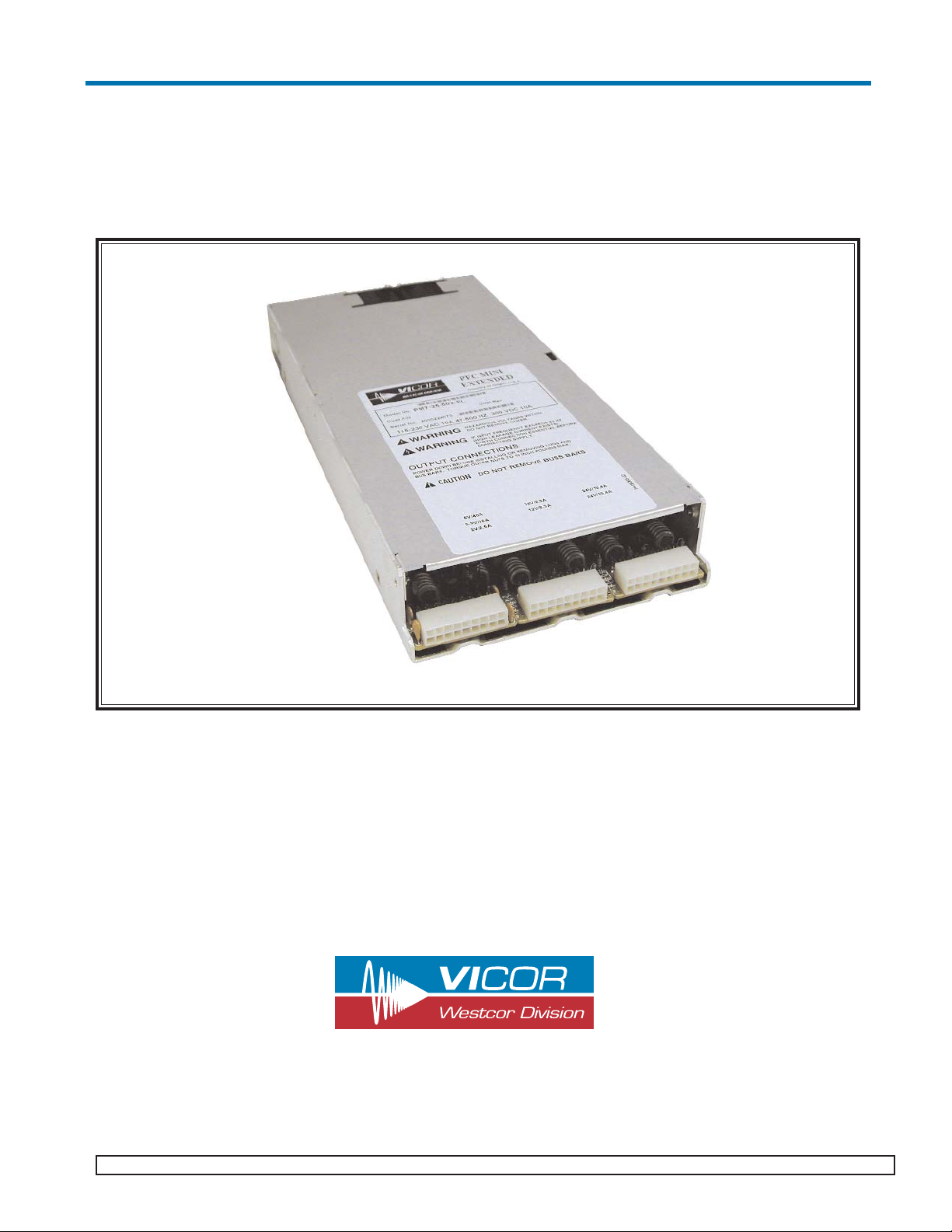
VICOR PFC Mini-EL Instructions for use

PFC Mini-EL™
Power Factor Corrected AC-DC Switcher
PFC Mini-EL Design Guide
Design Guide
and
“Quick Install” Instructions
www.vicorpower.com
Rev. 12/2003 Vicor 800-735-6200 Westcor Division 408-522-5280 Applications Engineering 800-927-9474

TABLE OF CONTENTS
Overview of Product...........................................................................................................................3
Part Numbering...................................................................................................................................3
Mechanical Considerations.................................................................................................................4
PFC Mini-EL Do’s and Don’ts............................................................................................................4
Technical Description..........................................................................................................................5
PFC Mini-EL Configuration Layout...................................................................................................6
Quick Install Instructions....................................................................................................................8
Mechanical Drawings..........................................................................................................................10
Output Connectors...............................................................................................................................11
Interface Connections..........................................................................................................................12
Using Batmod......................................................................................................................................16
7 Output PFC Mini-EL.......................................................................................................................16
Output Power Derating.......................................................................................................................17
Specifications......................................................................................................................................18
Current Share Board............................................................................................................................20
Pg 2 Vicor 800-735-6200 Westcor Division 408-522-5280 Applications Engineering 800-927-9474 Rev. 12/2003
PFC Mini-EL Design Guide

PFC Mini-EL™
Power Factor Corrected AC-DC Switcher
Overview
The PFC Mini-EL is an extremely low profile switching power supply that combines the advantages of power fac-
tor correction and high power density. It can provide up to 6 isolated outputs (3 slots) and each slot accommodates
the following Vicor DC-DC Converters.
1st Generation: 1 Full Size (VI-200) or 2 Junior modules (VI-J00)
2nd Generation: 1 Maxi, 2 Minis (Micros cannot be used)
The use of these converters give the PFC Mini-EL the inherent power flexibility typical of all Vicor products.
Accepting input voltages of 85 Vac to 264 Vac, and 100 to 380 Vdc, the PFC Mini-EL can provide up to 1,500
Watts in a package size of 1.72" H (43,6mm) x 6" W (152,4mm) x 13.2" L (335,3mm). The PFC Mini-EL is facto-
ry configured to meet user requirements.
A special 7 output PFC Mini is available in four models. See page 16 for more details.
Standard Features
• Power Factor Correction: 0.99 at 115 Vac; 0.95 at 230 Vac
• Universal Input: 85-264 Vac, 47-500 Hz, or 100-380 Vdc
• Power Output: 1,500W at 230 Vac; 800W at 115 Vac
• Up to 6 isolated outputs (3 slots)
• Fan cooled
• Full power to 45°C; half power at 65°C
• Conducted EMI: 1st Generation (VI-200, VI-J00) 2nd Generation (Maxi, Mini)
FCC Class B FCC Class A
EN 55022 Class B EN 55022 Class A
(certain configurations meet EN55022 Class B.)
• Low ripple: 50mVp-p max. 15V & less; 150mVp-p max. >15V to 24V; 1%Vout p-p max above 24V
• Harmonic Distortion complies with EN61000-3-2
• AC Power OK status signal
• Autosense (for more information, see page 8 and page 12)
• Output overcurrent protection on all outputs
• Output overvoltage protection and Output overtemperature limiting (not applicable when using VI-J00)
• Ride-through (holdup) time: >20 ms at 1,200W load (nominal line)
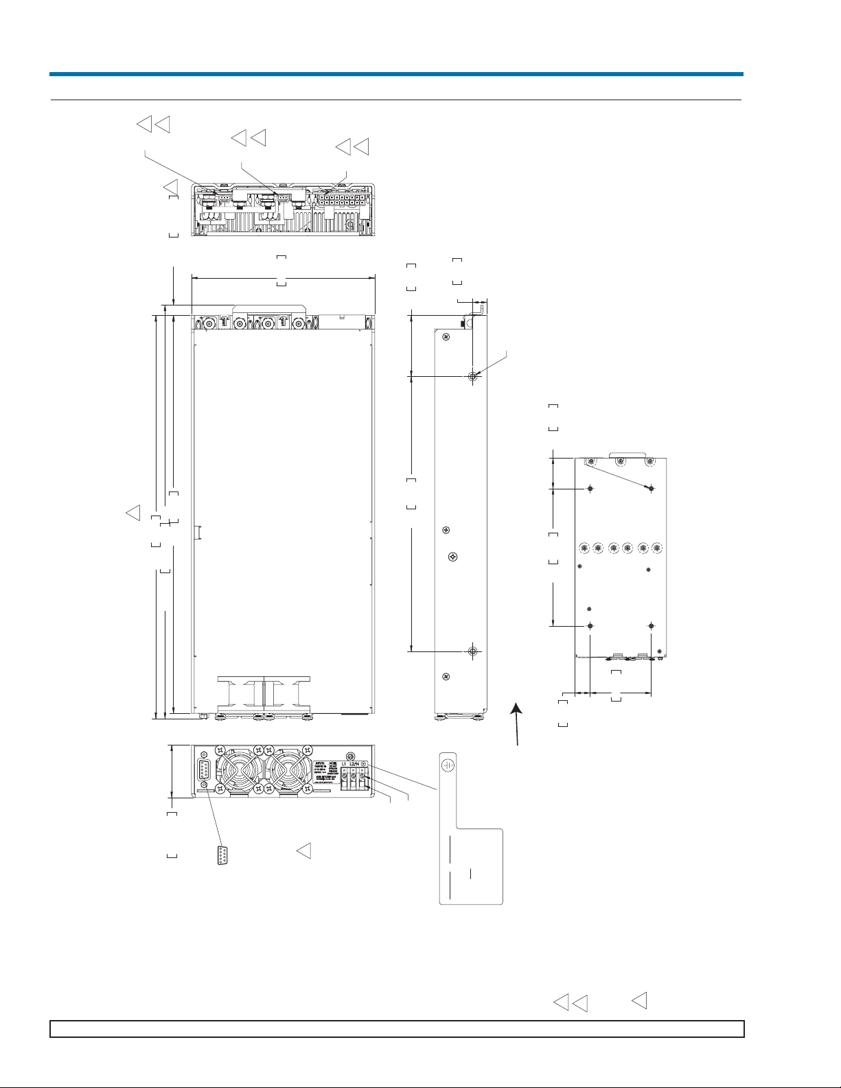
• Size: 1.72" H (43,6mm) x 6" W (152,4mm) x 13.2" L (335,3mm)
• Safety Agency Approvals: CE Marking, CTÜVUS
Optional Features
• Extended temperature range output converters
• Current Share Board - See page 20
• BatMOD current sources available (see page 16 for more information)
• Connector kits available (#19-130047 and # 19-130050)
Part Numbering
PFC Mini-EL PMx1-x2 x3-xxx -EL x1Number of outputs
e.g. PM4-22-501-EL x2Number of 1st Gen VI-200 & VI-J00 modules
x3Number of 2nd Gen Maxi and Mini modules
xxx Sequential number assigned by Westcor
EL Extended length
Rev. 12/2003 Vicor 800-735-6200 Westcor Division 408-522-5280 Applications Engineering 800-927-9474 Pg. 3
PFC Mini-EL Design Guide

Mechanical Considerations
The PFC Mini-EL can be mounted on either of two surfaces using standard 8-32 (4 mm) size screws. Maximum
allowable torque is 4.4 in. lbs., and the maximum penetration is 0.16 in. (4mm).
When selecting a mounting location and orientation, the unit should be positioned so air flow is not restricted.
Maintain a 2" (5,1cm) minimum clearance at both ends of the PFC Mini-EL, and route all cables so airflow is not
obstructed. The power supply draws air in at the fan side/AC input side and exhausts air out the load side. If air-
flow ducting is used, avoid sharp turns that could create back pressure. The fans move approximately 20 CFM of
air.
Avoid excessive bending of output power cables after they are connected to the output terminals. For high-current
outputs, use cable ties to support heavy cables and minimize mechanical stress on connectors. Be careful not to
short-out to neighboring outputs. The maximum torque recommended on output nuts is 10 in. lbs.
Avoid applications in which the unit is exposed to excessive shock or vibration levels. In such applications, a shock
absorbing mount design is required.
PFC Mini-EL Do’s and Don’ts
• Use twisted pair 20-22 AWG wire when installing Remote Sense.
•To prevent damage to supply, verify polarity of remote sense connection before turning supply on.
• Always turn the power supply off, before disconnecting input or output wires.
• When using the remote sense feature, the +Out and -Out load wires should never be disconnected while the
supply is operating. Failing to do so could damage the power supply.
• Do not restrict airflow to the unit. The cooling fan draws air into the unit and forces it out at the output power
terminals.
• Run the output (+/–) power cables next to each other to minimize inductance.
• Do not attempt to repair or modify the power supply in any manner. Contact Westcor’s Repair Service.
• Insert proper fault protection at power supply input terminals (i.e., a fuse).
• Use proper size wires to avoid overheating and excessive voltage drop.
Pg 4 Vicor 800-735-6200 Westcor Division 408-522-5280 Applications Engineering 800-927-9474 Rev. 12/2003
PFC Mini-EL Design Guide

Technical Description
The PFC Mini-EL consists of an off-line single phase, power-factor-corrected front end, EMI filter, cooling fan,
customer interface, associated housekeeping circuits, low noise filters and a selection of Vicor’s DC-DC convert-
ers.
Input AC mains voltage is applied to a terminal block. The input current is passed through an EMI filter designed
to meet conducted noise limit “B” specifications in FCC Part 15 and EN55022, Class B (with 1st Gen modules. If
2nd Gen modules are used, it meets FCC Class A and EN 55022 Class A. Certain configurations meet Class B).
At start-up, inrush current is limited by a PTC thermistor. The PTC is shunted out shortly after initial power-up by
a DC bus voltage sense circuit driving a relay. After rectification, the input voltage is put through a boost converter
that keeps the AC input current sinusoidal and synchronized with the input AC voltage (in compliance with
EN61000-3-2). The boost converter delivers a regulated input to the hold-up capacitors and a high voltage back-
plane. The backplane supplies power to the DC-DC converters that provide the desired low voltage regulated out-
puts.
Voltage conversion is achieved by Vicor’s family of Zero-Current-Switching (ZCS) DC-DC converters. These are
forward converters in which the main switching element switches at zero current. This patented topology has a
number of unique attributes: low switching losses; high frequency operation, resulting in reduced size for magnet-
ics and capacitors; excellent line and load regulation; wide adjustment range for output; low EMI/RFI emission
and high efficiencies.
At initial power-up, the PFC Mini-EL outputs are disabled to limit the inrush current and to allow the DC bus
potential to settle out to the correct operating level. A low-power flyback converter operating with PWM current-
mode control converts the high voltage DC bus into regulated low voltage to power the internal housekeeping cir-
cuits and DC cooling fans.
The internal housekeeping Vcc comes up within 2 s after the application of input power. Once the high voltage bus
is within operating limits, the AC Power OK signal asserts to a TTL "1," indicating the input power is OK, and
enables the power outputs. An auxiliary Vcc output of 5 Vdc sourcing up to 0.3A is provided for peripheral use.
An output Enable/Disable function is provided by using an optocoupler to control Vicor’s DC-DC converters. If
the Enable/Disable control pin is pulled low, the optocoupler turns on and disables the output. The nominal delay
associated for an output to come up when measured from release of the Enable/Disable pin is 5-10 ms. The
General Shutdown function controls all outputs simultaneously and works in a similar manner.
Rev. 12/2003 Vicor 800-735-6200 Westcor Division 408-522-5280 Applications Engineering 800-927-9474 Pg. 5
PFC Mini-EL Design Guide
Line Filter Rectifier Soft Start
Circuit Boost Converter
PFC Control
E/D Control
Low Noise
Output Card #1
Low Noise
Output Card #2
Low Noise
Output Card #3
Fan Isolated
Housekeeping
Power
Customer
Interface
Power
Output
Power
Output
Power
Output
Input
High Voltage
Bus
Enable/Disable Control
Current
Sample
Waveform
Sample
Figure 1. PFC Mini-EL Architecture

PFC Mini-EL Configuration Layout
Shown above are two sample PFC Mini-EL configuration layouts. The PFC Mini-EL has three
slots and each slot accomodates either full or half brick modules. Quarter bricks cannot be used.
Pg 6 Vicor 800-735-6200 Westcor Division 408-522-5280 Applications Engineering 800-927-9474 Rev. 12/2003
PFC Mini-EL Design Guide
Fan
AC input Fan
S2-M1S1-M1
Slot 1 Slot 2 Slot 3
Fan
AC input Fan
S3-M2
S3-M1
S2-M1S1-M1
Slot 1 Slot 2 Slot 3
S3-M1

PFC Mini-EL Configuration Layout
E/D = Enable/Disable
Rev. 12/2003 Vicor 800-735-6200 Westcor Division 408-522-5280 Applications Engineering 800-927-9474 Pg. 7
PFC Mini-EL Design Guide
Output #1
VI-J60-CY
E/D#3
Output #2
VI-J63-CW
E/D#3
V375A5C400AL1
E/D#2
V375A5C400AL1
E/D#1
SLOT#3SLOT#2SLOT#1
VI-J63CW1004.224.03 (M2)
VI-J60 CY50105.03 (M1)
V375A5C400AL12
V375A5C400AL1800805.01
ModulesWATTSAMPSVOLTSSLOT#
VI- CW1004.224.03 (M2)
VI- CY50105.03 (M1)
V375A5C400AL12
V375A5C400AL1800805.01
ModulesWATTSAMPSVOLTSSLOT#
Configuration Example:

PFC Mini-EL “Quick Install” Instructions (See pg 10 for mechanical drawings)
Mounting the PFC Mini-EL
* Mount the PFC Mini-EL on either of two sides.
* Use #8-32 or 4mm mounting screws. Maximum penetration should not exceed 0.16" (4mm).
* Maintain 2" (5,1cm) clearance at both ends of power supply for airflow.
Input Connections
Input Power MBJ1
* Apply input AC power to terminal block MBJ1 using a pressure screw
terminal.
* Strip length of AC power conductors to be .35 inches.
* Maximum torque is 4.4 lb-in.
*Place a fuse or circuit breaker in the input line for safety require-
ments.
* The connector manufacturer recommends the wires not be tinned. A fer-
rule can be used to prevent fraying.
Output Connections
Power Connections
Installing single output ring lugs and/or bus bars on output studs:
* The right stud is Positive and the left stud is the Return on single output
cards.
* Remove the top nut and place ring lug over output stud.
* Do not remove the lower nut next to the PCB.
* Replace and tighten the nut to a torque of 10 inch pounds. Do Not
Over-Tighten Nuts.
Installing power connectors on dual output cards (18 pin connectors):
* SxJ1-11, SxJ1-10, SxJ1-11 are Positive for output #1, while pins SxJ1-2,
SxJ1-3, SxJ1-12 are the Return. SxJ1-7, S3J1-8 and SxJ1-16 are Positive for
output #2, while pins SxJ1-9, SxJ1-17 and SxJ1-18 are the Return.
* Use Molex mating receptacle #39-01-2140 with #39-00-0039 terminals.
* Attach 18-24 AWG stranded wire using Molex tool #11-01-0197.
1Where x refers to the slot number.
Sense Connections
The PFC Mini-EL is equipped with a feature called Autosense. If Remote
Sense connections are not made or needed, no Local Sense selection is necessary
- simply hook up the output and the PFC Mini-EL will automatically operate in
Local Sense. If remote sense connections are made, the PFC Mini-EL will oper-
ate in a Remote Sense mode.
Sense Connections on single output card
* If Remote Sense is desired, remove jumpers MBJ1 and J3, located behind the
sense connector.
* Connector pin SxJ2-2 is the +Sense and SxJ2-3 is the -Sense.
* Use Molex mating receptacle #50-57-9403 with #16-02-0103 terminals.
* Attach terminals to 20-22 AWG stranded twisted pair wire using Molex tool #
11-01-0208.
* Attach opposite end of sense lines to point where regulation is desired.
*Verify that sense lines are not cross-connected.
Pg 8 Vicor 800-735-6200 Westcor Division 408-522-5280 Applications Engineering 800-927-9474 Rev. 12/2003
PFC Mini-EL Design Guide
L1
47 TO 500 Hz
300VDC ---
115-230 VAC 10A
EARTH GND
WITHOUT
OPERATE
DO NOT
INPUTS: NOTE:
L2/N
MSJ1-2 L2-NEUTRAL
MBJ1-3 L1
MBJ1-1 EARTH GROUND
INPUT CONNECTIONS
LABEL NO: 94-00047 REV B
NOTE: SET SCREW MAX
TORQUE = 4.4 IN. LBS.
Output Return
SxJ2
Output
SxJ1 Dual Output connector
T
T
+S
12
3
45
67
8
9
10
1112
13
14
15161718
+
-
-
-S
+
+-
++-
+S
-S+-
-
M1 Output
M2 Output
Locking Key
Pin 1 Identifier
Remove jumpers for
Remote Sense

Sense Connections on dual output cards
* If Remote Sense is desired, remove jumpers on MBJ1 and J3, located on
either side of the output connector.
* Connector pin SxJ1-4 is the +Sense and SxJ1-5 is the -Sense for output #1.
SxJ1-13 is the +Sense and SxJ1-15 is the -Sense for output #2.
* Use Molex mating receptacle #39-01-2180 with #39-00-0039 terminals.
* Attach 18-24 AWG stranded twisted pair wire using Molex tool #11-01-0197
.
Trim Connections
Trim Connections on single output cards:
* SxJ2-1 provides Trim access.
* Use Molex mating receptacle #50-57-9403 with #16-02-0103 terminals.
* Attach 20-22 AWG stranded wire using Molex tool #11-01-0208.
Trim Connections on dual output cards:
* SxJ1-14 provides Trim access for output #1, and SxJ1-6 provides Trim access
for output #2.
* Use Molex mating receptacle #39-01-21 with #39-00-0039 terminals.
* Attach 18-24 AWG stranded wire using Molex tool #11-01-0197.
Current Trim Connections when using BatMods:
* SxJ2-1 provides Current Trim access.
* Use Molex mating receptacle #50-57-9403 with #16-02-0103 terminals.
* Attach 22-24 AWG stranded wire using Molex tool #11-01-0208.
Interface Connections
* J3-1 to 3 are Enable/Disable for cards 1-3, respectively.
* J3-4 is Signal Ground, J3-5 is +5V, J3-6 is AC Power OK, and J3-7 is General
Shutdown.
* Use mating receptable AMP P/N 205204-4 with terminals AMP P/N 66506-9.
* Attach terminals to 18-24 AWG stranded wire.
Rev. 12/2003 Vicor 800-735-6200 Westcor Division 408-522-5280 Applications Engineering 800-927-9474 Pg. 9
PFC Mini-EL Design Guide
Remove jumpers for
Remote Sense on
Output # 1
Remove jumpers for
Remote Sense on
Output # 2
Connector J2
1
2
3
Trim Connector
Trim Pin Access
+Sense
-Sense
Pin
SxJ2
1
10
9
18
SxJ1 Dual Output connector
Pin 1 Identifier
Locking Key
2
3
4
56
7
8
11
12
131415
16
17
1
2
3
BatMod Current Source Connections
I
trim
V
trim
I
mon
Pin
SxJ2
J3-9 SPARE
J3 INTERFACE PIN OUT
J3-1
J3-2
J3-3
J3-4
J3-5
J3-6
J3-7
J3-8
E/D-1
E/D-2
E/D-3
SIGNAL GROUND
VCC +5V 300mA
ACOK AC POWER OK
GSD GENERAL SHUTDOWN
SPARE
J3 INTERFACE CONNECTION
MATING HDWR:
HOUSING: AMP P/N 205204-4
SCREW LOCK: AMP P/N 205980-4
TERMINALS: AMP P/N 66506-9
CRIMP TOOL: AMP 58448-3

PFC Mini-EL Mechanical Drawings
Pg 10 Vicor 800-735-6200 Westcor Division 408-522-5280 Applications Engineering 800-927-9474 Rev. 12/2003
PFC Mini-EL Design Guide
13.03 330.96
13.20 335.33
6.00 152.40
.34 ±.02 8.64 ±0.51
13.54 ±.02 343.97 ±0.51
2
2
1.72 ±.02 43.69 ±0.51
J3-1 E/D-1
J3-2 E/D-2
J3-3 E/D-3
J3-4 SIGNAL GROUND
J3-5 VCC +5V 300mA
J3-6 ACOK AC POWER OK
J3-7 GSD GENERAL SHUTDOWN
J3-8 SPARE
J3-9 SPARE
MATING HDWR: (AMP P/N: OR EQUIVALENT)
HOUSING: AMP P/N: 205204-4
TERMINALS: AMP P/N: 66506-9
SCREW LOCK: AMP P/N: 205980-4
CRIMP TOOL: AMP 58448-3
3
J3 INTERFACE PIN OUT
J3 INTERFACE CONNECTION
MBJ1 INPUT CONNECTIONS
MBJ1-1 EARTH GROUND
MBJ1-2 L2 / NEUTRAL
MBJ1-3 L1
CLAMPING SCREWS
14 AWG WIRE
S1J1
S2J1
S3J1
2.00 50.809.00 228.60
.47 11.94
CUSTOMER MOUNTING HOLES:
4X #8-32 X .156 or M4 X 4mm MAX LG.
FROM OUTSIDE OF POWER SUPPLY
9.00 228.60 2.00 50.80
1.00 25.40
4.00 101.60
CUSTOMER MOUNTING HOLES:
4X #8-32 X .156 or M4 X 4mm MAX LG.
FROM OUTSIDE OF POWER SUPPLY
BOTTOM VIEW
SCALE: 1:2
5 1
9 6
L1
47 TO 500 Hz
300VDC ---
115-230 VAC 10A
EARTH GND
WITHOUT
OPERATE
DO NOT
INPUTS: NOTE:
L2/N
LABEL NO: 94-00047 REV B
NOTE: SET SCREW MAX
TORQUE = 4.4 IN. LBS.
2
4
3
1. INTERPRET DRAWING PER ANSI Y 14.5-1994
WITH OPTIONAL BUS BAR
A COMPLETE SET OF MATING CONNECTORS CAN BE
PURCHASED FROM WESTCOR BY SPECIFYING
CONNECTOR KIT P/N: 19-130047. A KIT CONTAINING
40 EACH OF THE HI POWER 12 AMP 16 AWG CRIMP
PINS IS P/N: 19-130050.
REF DESIGNATION LEGEND
MB = MOTHER BOARD
S1 = (SLOT 1) DAUGHTERBOARD MODULES E/D 1
S2 = (SLOT 2) DAUGHTERBOARD MODULES E/D 2
S3 = (SLOTE 3) DAUGHTERBOARD MODULES E/D 3
Air Flow
SEE PAGE 11 FOR DETAILED OUTPUT
CONNECTION INFORMATION
3
4
3
4
3
4

Output Connectors for PFC Mini-EL
Rev. 12/2003 Vicor 800-735-6200 Westcor Division 408-522-5280 Applications Engineering 800-927-9474 Pg. 11
PFC Mini-EL Design Guide
2
3
4
5
6
7
8
11
12
13
14
15
16
17
110
918
1 +V OUT M1
2 -V OUT M1
3 -V OUT M1
4 + SENSE M1
5 - SENSE M1
6 TRIM M2
7 +V OUT M2
8 +V OUT M2
9 -V OUT M2
10 +V OUT M1
11 +V OUT M1
12 -V OUT M1
13 + SENSE M2
14 TRIM M1
15 - SENSE M2
16 +V OUT M2
17 - V OUT M2
18 - V OUT M2
MATING CONNECTOR:
18 PIN HOUSING: MOLEX (39-01-2180)
TERMINAL FEM CRIMP 18-24 AWG: MOLEX (39-00-0039)
USE CRIMP TOOL: MOLEX (11-01-0197)
FOR HIGH OUTPUT CURRENTS (>9A/PIN)
TERMINAL FEM CRIMP 16AWG: MOLEX (44476-3112)
USE CRIMP TOOL: MOLEX (11-01-0199)
PIN DESCRIPTION PIN DESCRIPTION
10-32 OUTPUT STUDS
TRIM
3
SxJ2 REMOTE SENSE/TRIM
PIN CONNECTOR
1
2
- SENSE
+ SENSE
MATING CONNECTOR:
HOUSING: MOLEX P/N 50-57-9403
TERMINALS: MOLEX P/N 16-02-0103
USE CRIMP TOOL: MOLEX P/N 11-01-0208
B. DUAL OUTPUT SLOT - 18 Pin Housing
A
. SINGLE OUTPUT SLOT
SxJ1 (18 PIN OUTPUT, REMOTE SENSE
AND TRIM PIN CONNECTOR)
-V OUT
+V OUT
M1 Output
M2 Output
OPTIONAL CONNECTOR KIT FOR PFC Mini-EL (PART # 19-130047. Available for purchase from Westcor)
ITEM QTY DESCRIPTION VENDOR # 1 PART NO.
1 3 HOUSING 3 POS .100 CTR W/LATCH MOLEX 50-57-9403
2 10 TERM FEM CRIMP 22-24AWG SEL GOLD MOLEX 16-02-0103
** CRIMP TOOL FOR ITEM 2 MOLEX 11-01-0208
3 1 HOUSING FEMALE D-SUB 09 PIN AMP 205204-4
3 10 TERM MALE CRIMP 22-24 AWG TIN AMP 66506-9
3 1 SCREW LOCK MALE (1 PAIR) AMP 205980-4
** CRIMP TOOL FOR ITEMS 3 AMP 58448-3
4 3 HOUSING 18 POS .165 CTR W/LATCH MOLEX 39-01-2180
5 60 TERM FEM CRIMP 18-24 AWG SEL GOLD MOLEX 39-00-0039
** CRIMP TOOL FOR ITEM 5 MOLEX 11-01-0197
** ITEMS FOR REF ONLY (NOT INCLUDED IN KIT)
PART # FOR OPTIONAL HIGH OUTPUT CURRENT PINS CONNECTOR KIT IS 19-130050.

Interface Connections
Chassis Input Power Terminals (MBJ1)
Input AC power is applied to terminal block MBJ1 using a pressure screw terminal that accepts a maximum wire
size of 14 AWG. The insulation should be stripped 0.35 inches and the maximum torque applied to the screws
should not exceed 4.4 lb-in. The connector manufacturer recommends the wires not be tinned. A ferrule (Phoenix
P/N 32-00-58-0, provided in optional connector kit) can be used to prevent fraying. MBJ1-1 (GND) is Earth
Ground for safety; MBJ1-2 (L2) and MBJ1-3 (L1) are the other "hot" connections.
A fault clearing device, such as a fuse or circuit breaker, with a maximum 15A rating at the power supply input is
required for safety agency compliance. It should be sized to handle the start-up inrush current of 30A at 115 Vac
and 60A at 230 Vac.
Output Power Connections
There are two types of output power terminals available in the PFC Mini-EL. Outputs from full-sized converters
are terminated in two 10-32 plated steel bolts. The positive polarity of the output is the right bolt when viewed
from the output end. Outputs from half-sized converters terminate in a Molex connector. Each power output is iso-
lated, so outputs of positive or negative polarity can be configured through proper selection of the output reference
terminal.
In order to minimize parasitic cable inductance and reduce EMI, the output power cables should be routed in close
proximity to one another, and large current loops should be avoided. To avoid excessive voltage drop, do not
undersize power cables, especially for high current outputs. Excessive cable inductance coupled with large capaci-
tive loading can introduce instability in switching power supplies. This problem can be avoided with proper system
design. Consult Vicor’s Applications Engineering Department for assistance with applications that use long cable
lengths and excessive load capacitance.
+Sense/–Sense (SxJ2/SxJ1) (Not applicable when using BatMod current source.)
The PFC Mini-El is equipped with Autosense. If Remote Sense connections are not made or needed, no Local
Sense selection is necessary - simply hook up the output and the PFC Mini-EL will automatically operate in Local
Sense. If remote sense connections are made, the PFC Mini-EL will operate in a Remote Sense mode.
When Local Sense is used, the power supply will regulate the output at the output terminals. The voltage appearing
at the load may drop slightly due to voltage drop in the power cables. If it is necessary to compensate for voltage
Pg 12 Vicor 800-735-6200 Westcor Division 408-522-5280 Applications Engineering 800-927-9474 Rev. 12/2003
PFC Mini-EL Design Guide
L1
47 TO 500 Hz
300VDC ---
115-230 VAC 10A
EARTH GND
WITHOUT
OPERATE
DO NOT
INPUTS: NOTE:
L2/N
MSJ1-2 L2-NEUTRAL
MBJ1-3 L1
MBJ1-1 EARTH GROUND
INPUT CONNECTIONS
LABEL NO: 94-00047 REV B
NOTE: SET SCREW MAX
TORQUE = 4.4 IN. LBS.
Output Return
SxJ2
Output
1
10
9
18
23
456
7
8
11
12
13
14
15
16
17
18 Pin DUAL MINI AND JR. MODULE OUTPUT CONNECTIONS
SxJ1-15.
SxJ1-6.
SxJ1-7. SxJ1-16.
PIN DESCRIPTION
SxJ1-1.
PIN DESCRIPTION
SxJ1-2.
SxJ1-3.
SxJ1-4.
SxJ1-5.
SxJ1-10.
SxJ1-11.
SxJ1-14.
SxJ1-12.
SxJ1-13.
SxJ1-9. SxJ1-18.
SxJ1-8. SxJ1-17.
+OUTPUT M1 +OUTPUT M1
+OUTPUT M1
-OUTPUT M1
-OUTPUT M1 -OUTPUT M1
-OUTPUT M2
-OUTPUT M2
-OUTPUT M2
+OUTPUT M2
+OUTPUT M2
+OUTPUT M2
TRIM M1
TRIM M2
-SENSE M1
-SENSE M2
+SENSE M1 +SENSE M2
Figure 2. Input Power Terminal MBJ1
Figure 3. Power Connections for Single
Output
Figure 4. Power connections for Dual Output

drop along the output power cables, the output can be trimmed up or configured for Remote Sense. Use stranded
twisted pair 20-22 AWG wire for the Remote Sense lines. Remote Sense can compensate for a voltage drop of up
to 0.5V, or 0.25V on each leg.
The Sense connector for a single output board is a 3 pin connector providing the +Sense connection on SxJ2-2 and
the -Sense connection on SxJ2-3. The Sense connector for a dual output board is a 18 pin connector that also pro-
vides the output and trim connections. +Sense and -Sense for the first output are located on SxJ1-4 and SxJ1-5,
respectively. +Sense and -Sense for the second output are located on SxJ1-13 and SxJ1-15, respectively.
External Trim (SxJ2/SxJ1) (Not applicable when using BatMod current source)
OUTPUT MODULE Vref RTH
VI-200/VI-J00 ≥3.3V 2.5V 10kΩ
VI-200/VI-J00 <3.3V 0.97V 3.88kΩ
2nd Generation (Predefined) 1.23V 1kΩ
2nd Generation (User Defined) 1.23V Consult Factory
Table 1. Module Internal Reference Voltages and Thevenin Resistances.
The output voltage can be trimmed using an optional factory installed Trim potentiometer or with the Trim pin. The Trim
potentiometer is located next to the output connectors. If external trim is used, the Trim pin at SxJ2 is referenced to the -
Sense pin and can be used for external control of the output voltage. For dual output cards, the Trim pins are available at
SxJ1-14 and SxJ1-6 for outputs 1 and 2, respectively. A 10% increase to the trim pin voltage will result in a 10% increase in
output voltage. Reducing the trim pin voltage by 10% will result in a 10% decrease in output voltage.
Note: Converters are sometimes pretrimmed at the factory if a nonstandard output voltage is requested. If a nonstandard
voltage is requested, the resistor calculations will differ from those below. Consult the factory for assistance.
Rev. 12/2003 Vicor 800-735-6200 Westcor Division 408-522-5280 Applications Engineering 800-927-9474 Pg. 13
PFC Mini-EL Design Guide
Load
+Out
+Sense
-Sense
-Out
Use 20-22 AWG Twisted Pair Wires
Figure 5. Remote Sense
(Remote Sense)
Load
+P +Out
SxJ2-2 +Sense
SxJ2-3 -Sense
-P -Out
Use 20-22 AWG Twisted Pair Wires
R5
V
Ref
SxJ2-1
R6
R8
R7
To Error
Amplifier
R4
R3
R2
R1
+
+
V2
V1
-
-
RTH
Use 20-22 AWG
Twisted Pair Wires
Figure 6. External Trim

Example:
±±10% trim adjust on a 12V nominal output.
Figure 6 shows a typical variable trim circuit. Using a 10k trimpot (R7), the resistor values for R6 and R8 can be
calculated as follows:
V1= Vref + 10% = 2.75V Given: Vref = 2.5V (see Table 1)
IR5 = (2.75V - Vref)/RTH = (2.75V - 2.5V)/10kΩ= 25µA Given: RTH = 10kΩ(see Table 1)
Setting the bottom limit:
VR6 = 2.5V - 10% = 2.25V
And since IR5 = IR6 = 25µA,
R6 = VR6/IR6= 2.25V/25µA = 90kΩ
V2= V1+ VR6 = 2.75V + 2.25V = 5V
IR7 = V2/R7 = 5V/10kΩ= 500µA
IR8 = IR7 + IR6 = 525µA
VR8 = (Vnom +10%) - V2= 13.2V - 5V = 8.2V Given: Vnom = 12V
R8 = VR8/IR8 = 8.2V/525µA = 15.62kΩ
Consult Applications Engineering when trimming outputs below 5V.
Signal Ground (J3-4)
Signal Ground on J3-4 is an isolated secondary ground reference for all J3 interfacing signals. This is not the same
as Earth Ground on input power connector MBJ1.
Enable/Disable (J3-1 to J3-3)
The Enable/Disable control pins allow outputs to be sequenced either on or off. J3-1 through J3-3 are the control
pins for output cards 1 through 3, respectively. For 2-output cards, both outputs are enabled or disabled with a sin-
gle control. The Enable/Disable pins should be pulled low to less than 0.7V with respect to Signal Ground to dis-
able the outputs. They will source 4mA maximum. These pins should be open circuited or allowed to exceed 4.5V
when enabled. Do not apply more than 5V to these inputs.
Enable/Disable control of 2nd Generation Module Arrays
When using the Enable/Disable function on an output that consists of two or more 2nd Gen modules, it is neces-
sary to connect the E/D pins of the corresponding module locations together such that both modules are command-
ed to turn ON or OFF simultaneously.
Pg 14 Vicor 800-735-6200 Westcor Division 408-522-5280 Applications Engineering 800-927-9474 Rev. 12/2003
PFC Mini-EL Design Guide
PFC Mini
4
7
Signal Ground
General Shutdown
Enable/Disable Output 1
J3
1
0
TTL "1" (OFF)
TTL "0" (ON)
A TTL "1" applied to the base of the transistor turns
output OFF. Pin 1 (or Pin 7 for GSD) is pulled Low
with respect to Signal Ground.
5Vcc
1
Enable/Disable Control
Figure 7. Enable/Disable and General Shutdown

Example: S1 and S2 has been configured as a single output parallel array (see Fig. 8)
In order to disable the 48V output, E/D 1 and E/D 2 should be shorted together as shown in Fig. 8. With E/D 1
and 2 connected together, a single switch can then be used to remotely enable and disable the output.
**Note: For single output 2nd Gen power supply configurations, the simplest method of remotely enabling and
disabling the output is to use the General Shutdown (GSD) function.
General Shutdown /GSD (J3-7)
The GSD control pin on J3-7 allows simultaneous shutdown of all outputs. This pin must be pulled down to less
than 0.7V, and will source 4mA maximum to shut down all outputs. The GSD pin should be open circuited or
allowed to exceed 4.5V when not in use, or when the outputs are to be enabled. Do not apply more than 5V to this
input at any time. Normal open circuit voltage is 1.5 to 3V with respect to Signal Ground.
AC OK (J3-6)
AC OK is an active high TTL compatible signal and provides a status indication of the AC input power. It is on pin
J3-6 and is capable of sinking 16 mA maximum. This signal switches to a TTL "1" when the high voltage bus
exceeds low-line condition during turn-on. Upon loss of input power, the bus voltage will drop, causing the AC
OK signal to go low. A minimum of 3 ms holdup time is provided for a 1,200W load following the loss of the AC
OK signal.
Auxiliary Vcc +5V/0.3A (J3-5)
The Vcc on J3-5 is an auxiliary 5V regulated power source. It is +5 Vdc +/–5% with respect to Signal Ground and
can supply 300 mA maximum. It is short-circuit-proof, but if shorted, all outputs will shut down through the
Enable/Disable circuitry.
Rev. 12/2003 Vicor 800-735-6200 Westcor Division 408-522-5280 Applications Engineering 800-927-9474 Pg. 15
PFC Mini-EL Design Guide
Load
V375A48C600A
V373A48C600A
V375A5C400A
1
2
3
4
5
6
7
8
9
1
2
3
1
2
3
1
2
3
J3
J1
S1
S2
S3
Figure 8. Enable/Disable Control of 2nd Gen Module Arrays
10K
Signal Ground
AC Power OK
+5V
J3
2.49K
PN2222
Pin 4
Pin 6
Figure 9. AC OK

Using a BatMod Current Source in the PFC Mini-EL
The BatMod is a programmable current source that can also be used as a constant voltage converter. It has three
control signals that can be found on SxJ2. All three are referenced to the -Out pin. Current Trim (SxJ2-1) is an
input signal with an analog voltage of one to five volts that can adjust the sourced current rating from 0 to 100%.
Voltage must be applied to the Current Trim input for the module to provide power. The Voltage Trim (SxJ2-
2) is an input signal that can be set for a maximum voltage with a fixed resistor, or adjusted by using an external
voltage source. A source voltage referenced to the -Out of 1.25 to 2.5V for a 50% to 100% of rated voltage adjust-
ment. Leaving the Voltage Trim open will set the trim limit to maximum. The Current Monitor (SxJ2-3) is an out-
put signal that indicates the amount of current being sourced. It is a linear voltage/current relationship in which one
volt corresponds to 0% of sourced current, and five volts corresponds to 100% of sourced current.
Single Output Power Supplies (Arrays)
Westcor’s standard configuration for single output power supplies is to set the left module (as seen from looking at
the power supply output) as the controlling module of the array.
Special 7 Output PFC Mini-EL
A special 7 output PFC Mini-EL is available in four models. See table below for more information.
Pg 16 Vicor 800-735-6200 Westcor Division 408-522-5280 Applications Engineering 800-927-9474 Rev. 12/2003
PFC Mini-EL Design Guide
78M05 Auxiliary Vcc
J3-5
0.1 µF
Signal Ground
J3
J3-4
+5V/300 mA
Figure 10. Auxiliary Vcc
PM7-43-01-EL PM7-25-02-EL PM7-25-03-EL PM7-07-04-EL
MAXIMUM CURRENT
- 2.0 3 3 3 3
-5.2 16 16 16 16
± 5.0 40 40 40 40
± 12.0 8.3 8.3 20.8 20.8
± 12.0 8.3 8.3 20.8 20.8
± 24.0 4.2 10.4 4.2 10.4
± 24.0 4.2 10.4 4.2 10.4
O
U
T
P
U
T
V
O
L
T
A
G
E
Maximum
Output
Power
690W 790W 990W 1,290W

PFC Mini-EL Output Power vs. Input Voltage
Rev. 12/2003 Vicor 800-735-6200 Westcor Division 408-522-5280 Applications Engineering 800-927-9474 Pg. 17
PFC Mini-EL Design Guide
PFC M ini
Output Power vs. AC Input Voltage
0
200
400
600
800
1000
1200
1400
1600
85 105 125 145 165 185 205 225 245 265
AC Input Voltage
Output Power
200 Vac
638W
PFC M ini
Output Power vs. DC Input Voltage
0
200
400
600
800
1000
1200
1400
1600
100 120 140 160 180 200 220 240 260 280 300 320 340 360 380
DC Input Voltage
Output Power
750W

Specifications (Typical at 25°C, nominal line and 75% load, unless otherwise specified)
GENERAL
Number of Outputs 1-6
Efficiency > 80%
Safety Approvals cTÜVus, CE MARKING
Maximum Output Power 600W, 115/230 Vac (VI-200/VI-J00 Modules) +
800W, 115 Vac (1st and 2nd Generation Modules) +
1,200W, 230 Vac (2nd Generation Modules <= 12V)
1,500W, 230 Vac (Selected 2nd Generation Modules)
+ Note: Not to exceed an input current of 10A
INPUT
Input 85-264 Vac, 47-500Hz
100-380 Vdc
Line/Load Regulation Ist Gen: ± 0.2% max.10% to full load
± 0.5% max. No load to 10% load
Line Regulation* 2nd Gen:± 0.20% max. to 0.3% max LL to HL, Full Load
Inrush Current* 33A pk @ 115 Vac
65A pk @ 230 Vac
Ride Through Time 20 ms at 1,200W load
Conducted EMI 1st Gen 2nd Generation
FCC Class B FCC Class A
EN 55022 Class B EN 55022 Class A
(some configurations may meet Class B)
Power Factor 0.99 (115 Vac 800W load): 0.95 (230 Vac 1,200W load)
Transient Burst Immunity EN 61000-4-4, Level 3, Performance Criteria B
Surge Immunity EN 61000-4-5 Installation Class 3, Performance Criteria B
Dielectric Withstand Primary to Chassis GND = 2,121 Vdc
Primary to Secondary = 4,242 Vdc
Secondary to Chassis GND = 750 Vdc
* See Vicor module specifications. A preload may be necessary for modules trimmed down below 90% of normal
output voltage.
OUTPUT
VI-200/VI-J00 Modules
Parameter MIN. TYP. MAX. UNITS NOTES
Setpoint Accuracy* 0.5 1 % of Vnom
Load/line Regulation ± 0.2 % 10% to full load
Load/line Regulation ± 0.5 % No load to 10% load
Temperature Regulation 0.01 0.02 %/°C Over rated temp.
Long Term Drift 0.02 %/K hours
Output Ripple & Noise:
15V and below 50 mV p-p
> 15V to 24V 150 mV p-p
>24V 1.0 % Vout
Voltage Trim Range
1st Gen Slots 50-110 % V out ± 10% on 10-15 Vout
Total Remote Sense Compensation 0.5 Volts Autosense. See pg.6 & 11
OVP Set Point1115 125 135 %Vout Recycle Power
Current Limit 105 115 125 % of I max Auto Recovery
Short Circuit Current 20 (1052) 130 %
Overtemperature Limiting Not available on VI-J00
* For special and adjustable voltages, maximum setpoint accuracy is 2% of Vnom.
1131% Nominal for Booster Modules. No OVP for VI-J00
2 VI-J00 modules only.
Pg 18 Vicor 800-735-6200 Westcor Division 408-522-5280 Applications Engineering 800-927-9474 Rev. 12/2003
PFC Mini-EL Design Guide

OUTPUT (CONT’D.)
2nd Generation Modules (Maxi and Mini modules only)
Parameter MIN. TYP. MAX. UNITS NOTES
Setpoint Accuracy* ±0.5 ±1 % of VNOM
Load Regulation ±0.1 % of VNOM See module design guide for
exact specifications.
Temperature Regulation 0.002 0.005 %/°C -20 to 100°C
Long Term Drift 0.02 %/K hours
Output Ripple and noise:
15V and below 50 mV p-p
> 15V to 24V 150 mV p-p
>24V 1.0 % Vout
Voltage Trim Range
2nd Gen Slots 10-110 % Vout Preload may be required.
Total Remote Sense Compensation 0.5 Volts Autosense. See pg.6 & 11
OVP Set Point 112 135 % of Vout Recycle power
Current Limit 115 135 % of I max Auto Recovery
Overtemperature Limiting 100 115 2nd Gen OTL is non-latching
* For special, adjustable voltages and 48Vdc outputs, maximum setpoint accuracy is 2% of Vnom.
Note: See individual module datasheets for specific module specifications.
ENVIRONMENTAL
Storage Temperature -40°C to +85°C
Operating Temperature
Full Power -20 to +45°C*
Half Power -20 to +65°C
* 45°C is the maximum operating temperature. If one is using a 2nd Gen module less than 24V output and more than 500
Watts, the maximum operating temperature is 40°C.
Specific temperature data on all module configurations can be obtained by contacting Applications Engineering.
Altitude Derate 2.6% total output power for each 1,000 ft to a maximum
operating altitude of 15,000 ft. Non-operating storage maximum
altitude is 40K.
75% maximum load
Humidity 0 to 95% non condensing
Product Weight 6.0 lbs. (2,7 kg)
Dimensions 1.72" H (43,6mm) x 6.0" W (152,4mm) x 13.2" L (335,3mm)
Warranty* 2 years limited warranty. See vicorpower.com for complete warranty
statement.
* Opening, repairing or modifying the unit will void the warranty. If you have any problem with the power supply,
please contact Customer Service at 1-800-797-5678. If the unit needs to be returned for inspection/analysis, an
RMA number will be issued. All units must have a RMA number prior to return.
Rev. 12/2003 Vicor 800-735-6200 Westcor Division 408-522-5280 Applications Engineering 800-927-9474 Pg. 19
PFC Mini-EL Design Guide

Pg 20 Vicor 800-735-6200 Westcor Division 408-522-5280 Applications Engineering 800-927-9474 Rev. 12/2003
PFC Mini-EL Design Guide
"Current sharing" also known as Load Sharing,
is the ability to divide the output current even-
ly across all active power supplies. This great-
ly reduces stresses on each power supply and
allows them to run cooler, resulting in higher
reliability. Standard "current sharing" tech-
niques typically utilize shunt resistors or Hall
Effect devices to measure the current from
each power supply. Power shunt resistors con-
tinually dissipate power and require cooling
especially when dealing with high output cur-
rents of >100Amps. Hall Effect devices meas-
ure magnetic fields generated by current flow-
ing through a conductor and, although they dis-
sipate no power, they tend to be large and
expensive.
First developed by Westcor Engineering for
paralleling MegaPAC supplies, the Box-to-
Box Current Share Board or CSB allows two
or more Vicor power supplies to current share
by utilizing the inherent voltage drop produced
in the negative output return cable. This elim-
inates the need for additional shunt resistors or
expensive Hall Effect devices and provides a
simple 5 wire connection method to achieve a
+/-1mV accuracy between the Negative Output
power rails. This accuracy translates to a 1%
current sharing if there is a total of 100mV
conductional voltage drop in the negative
return path.
Constructed as a current source to drive the
Trim pin of a Vicor module, the design uses an
accurate comparator circuit to monitor the
power returns. In addition, the circuit is unidi-
rectional and can only trim an output voltage
up. The benefit is that only the supply that is
supporting less current is adjusted up. This
action balances the currents to the load by
matching the output voltages of the supplies.
In the case of one supply failing, the circuit
will attempt to trim the failed supply only.
This will leave the remaining functional supply
alone to provide power to the load at its nomi-
nal voltage. Thus the circuit also offers simple
redundancy. In addition, because CSB func-
tions as a current source, the Trim outputs (T1
and T2) of the CSB can be placed in parallel to
create a summing node. This allows current
sharing between more than two supplies by
paralleling the T2 output of one CSB circuit
with the T1 output of the next CSB.
Please note: The CSB is not intended for use in Hotswap Applications.
Requirements:
1. For proper operation, the power supplies being paralleled should be
enabled at the same time.
2. -Out conductors must be of equal length and wire gauge. Separate -Out
conductors must be used from each supply to the load, or the use of a "Y"
connection to a common point must be used as shown in figure 1. Each
leg of the "Y" must have a minimum of a few millivolts of drop in order
for proper operation. 50mV to 100mV of drop will provide from 5% to 1%
accuracy.
3. -V1 and -V2 for all Box-to-Box circuits must be connected directly at
the negative output power studs or terminals to achieve accurate current
sharing.
4. D* can be added if redundancy is needed. If redundancy is not required,
D* can be replaced with direct wire connections.
5. When using D*, the Power input should be connected on the cathode
side of the paralleling diodes as shown above.
6. Terminate Sense Leads either locally or remotely as shown in figure 1.
7. For paralleling more than 2 supplies consult factory for assistance.
CURRENT SHARE BOARD - Optional Feature
Figure 1. CSB Interconnect Example
Power Supply 1
24V@1kW
+OUT
+S
-OUT
-S
TRIM
Power Supply 2
24V@1kW
+OUT
+S
-OUT
-S
TRIM
T1
-V1
T2
-V2
Power
+VOUT
-VOUT
D*
D*
CSB02
Black
White
Brown
Yellow
Red
Table of contents
Other VICOR Power Supply manuals