Emerson Smart Wireless THUM Adapter User manual

Quick Start Guide
00825-0100-4075, Rev FA
June 2016
Emerson™ Smart Wireless THUM™
Adapter

June 2016
2
Quick Start Guide
NOTICE
This guide provides basic guidelines for the Emerson Smart Wireless THUM Adapter. It does not provide
instructions for detailed configuration, diagnostics, maintenance, service, troubleshooting, or installations.
Refer to the THUM Adapter Reference Manual (document number 00809-0100-4075) for more instruction.
The manual and this guide are also available electronically on www.rosemount.com.
This device complies with Part 15 of the FCC Rules. Operation is subject to the following conditions. This
device may not cause harmful interference. This device must accept any interference received, including
interference that may cause undesired operation.
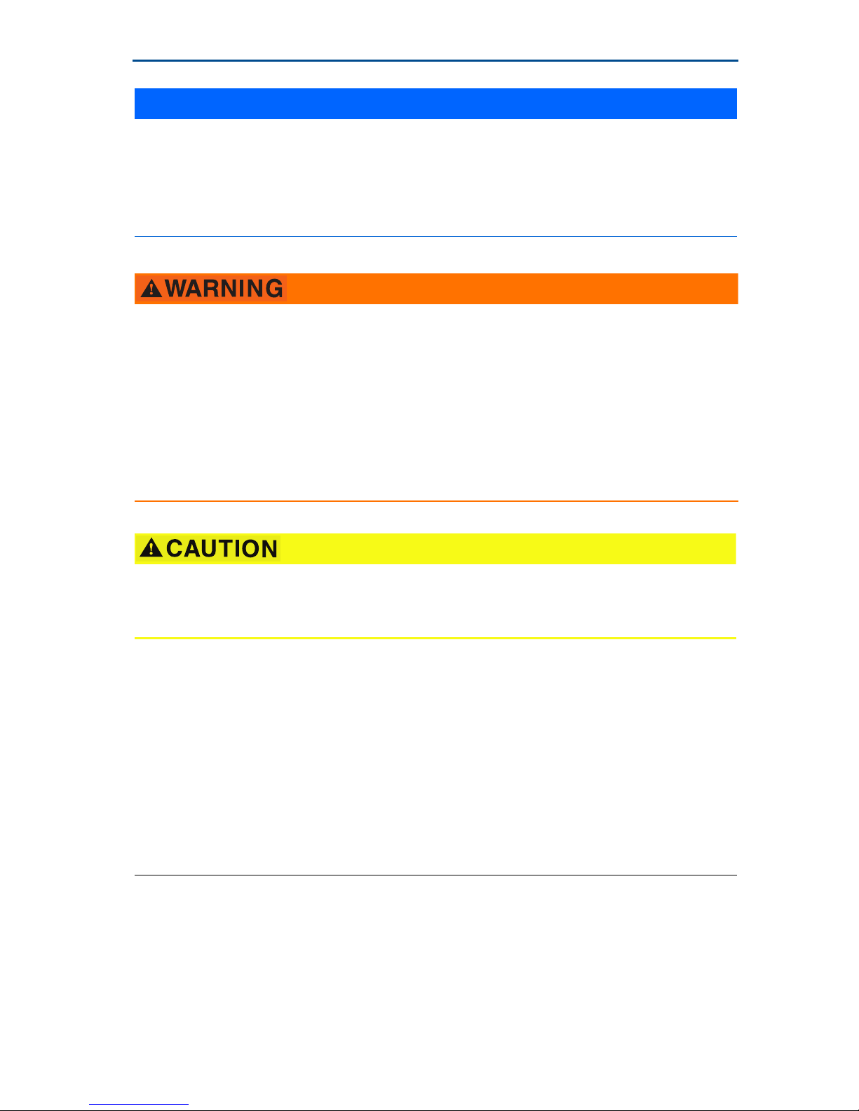
Explosions could result in death or serious injury.
Installation of this transmitter in an explosive environment must be in accordance with the appropriate local,
national, and international standards, codes, and practices. Review the Product Certifications section for any
restrictions associated with a safe installation.
Before connecting a Field Communicator in an explosive atmosphere, ensure the instruments are installed
in accordance with intrinsically safe or non-incendive field wiring practices.
Electrical shock can result in death or serious injury.
Avoid contact with the leads and terminals. High voltage that may be present on leads can cause electrical
shock.
This device must be installed to ensure a minimum antenna separation distance of 7.87-in. (20 cm) from all
persons.
During normal operation, or in fault condition, the THUM Adapter will cause a 2.5 V drop in the connected
loop. It is important to ensure that the power supply can provide at least 2.5 V more than the minimum
operating voltage of the wired device to make sure it works properly with the THUM Adapter installed. To
determine the minimum operating voltage for the wired device, review the wired device operation and
installation manual.
Contents
Wireless considerations . . . . . . . . . . . . . . . . . . . 3
Bench top configuration . . . . . . . . . . . . . . . . . . . 5
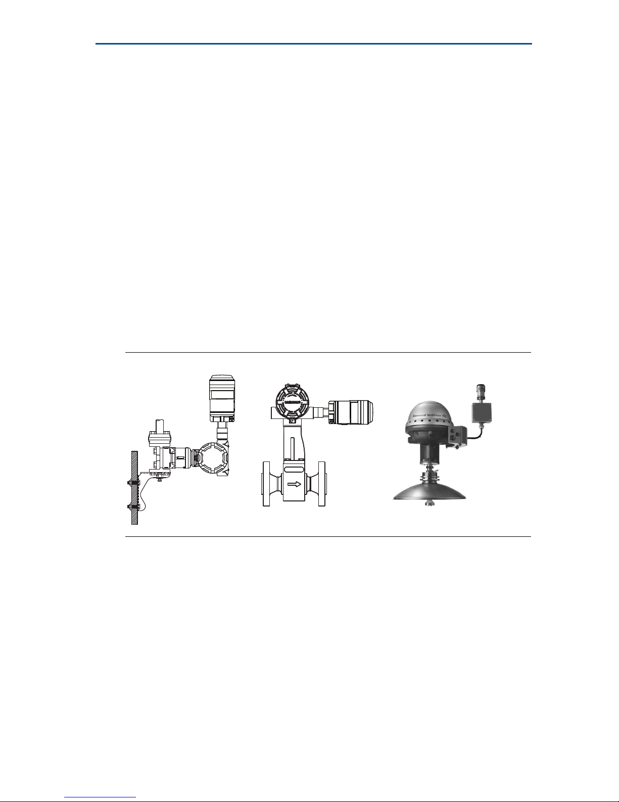
Physical installation . . . . . . . . . . . . . . . . . . . . . . . 6
Direct mount . . . . . . . . . . . . . . . . . . . . . . . . . . . . 6
Remote mount . . . . . . . . . . . . . . . . . . . . . . . . . . . 7
Device network configuration . . . . . . . . . . . . . 20
AMS Wireless Configurator . . . . . . . . . . . . . . . 20
Field Communicator . . . . . . . . . . . . . . . . . . . . . 21
Loop current test . . . . . . . . . . . . . . . . . . . . . . . . 21
Verify operation . . . . . . . . . . . . . . . . . . . . . . . . . 23
Reference information . . . . . . . . . . . . . . . . . . . 24
Product Certifications . . . . . . . . . . . . . . . . . . . . 25

Quick Start Guide
3
June 2016
1.0 Wireless considerations
1.1 Power up sequence
Power should not be applied to any wireless device until the Smart Wireless
Gateway (“Gateway”) is installed and functioning properly. Wireless devices
should also be powered up in order of proximity from the Gateway, beginning
with the closest. This will result in a simpler and faster network installation. Enable
Active Advertising on the Gateway to ensure that new devices join the network
faster. For more information see the Smart Wireless Gateway Manual (document
number 00809-0200-4420).
1.2 THUM Adapter position
THUM Adapter should be positioned vertically straight up, and should be
approximately 3 ft. (1 m) from any large structure, building or conductive surface
to allow for clear communication to other devices. If the THUM Adapter is
mounted horizontally wireless communication range may be decreased. The
THUM Adapter should not be mounted vertically straight down. See THUM
Adapter reference manual (document number 00809-0100-4075) for more
information.
Figure 1. THUM Adapter Position
1.3 Conduit entry
When installing the THUM Adapter into the conduit entry of a wired device, use
an approved thread sealant. Thread sealant provides a water tight seal. The
thread sealant also provides lubrication to ensure easy removal of the THUM
Adapter.
1.4 M20 conduit adapter
When using the M20 Conduit Adapter on the THUM Adapter, use an approved
thread sealant and tighten wrench tight to the THUM Adapter. When installing
the M20 conduit adapter into a conduit, tighten to 32.5 N-m/25 ft-lb to ensure
water tight seal.

June 2016
4
Quick Start Guide
Field Communicator connections
In order for the Field Communicator to interface with the THUM Adapter, the
wired device must be powered. The Field Communicator must be put into poll
mode and should use the THUM Adapter address of 63.
1.5 Power supply
Minimum loop load of 250 Ohms.
The THUM Adapter communicates via and derives power from a standard
4–20 mA/HART®loop. The THUM Adapter causes a small voltage drop on the
loop which is linear from 2.25 V at 3.5 mA to 1.2 V at 25 mA. Under fault
conditions, the maximum voltage drop is 2.5 V. The THUM Adapter will not
affect the 4–20 mA signal under normal or fault conditions as long as the loop
has at least a 2.5 V margin at the maximum loop current (25 mA for a typical
4–20 mA/HART device).
Limit the power supply to 0.5 Amps maximum and voltage to 55 Vdc.
1.6 Load resistor
If required, add a load resistor as shown in Figure 8 on page 10, Figure 12 on
page 13, and Figure 16 on page 15. The resistor should be adequately rated for
the application (1W minimum) and be compatible with the supplied splice
connector which accepts wire sizes from 14 to 22 AWG.
1.7 Loop
To ensure proper operation, the THUM Adapter should not be installed on a HART
loop with other active HART masters. HART masters that are active periodically,
such as a field communicator can be used on a loop with a THUM Adapter.
Loop current THUM Adapter voltage drop
3.5 mA 2.25 V
25 mA 1.2 V

Quick Start Guide
5
June 2016
2.0 Bench top configuration
When performing bench top configuration it is suggested that you connect the
THUM Adapter to a wired device. If this is not possible, the following wiring
diagrams can be used. For bench top configuration, ensure the power supply
used is limited to 0.5 Amps maximum.
Figure 2. THUM Adapter Only, Powered by a Current Source
Figure 3. THUM Adapter Only, Powered by a 24 V Power Supply with 1200
Ohm Resistor to Limit Current to 20 mA
A. THUM Adapter C. 20 mA current source
B. Ground D. HART Modem
A. THUM Adapter C. 20 V power supply
B. Ground D. HART Modem
A
Green
Red
Black
White
Yellow
B
C
D
+
-
Green
Red
Black
White
Yellow
A
B
C
+
-
D

June 2016
6
Quick Start Guide
3.0 Physical installation
The THUM Adapter can be installed in one of two configurations:
1. Direct mount: The THUM Adapter is connected directly to the conduit entry
of the wired device.
2. Remote mount: The THUM Adapter is mounted separate from the wired
device housing and then connected to the wired device using conduit or other
suitable means.
Figure 4. Direct Mount
4.0 Direct mount
1. Install the HART device according to standard installation practices and the
manufacturer’s instructions, being sure to use an approved thread sealant on
all connections.
2. Attach the THUM Adapter to the wired device as shown in Figure 4 on page 6.
3. Connect the THUM Adapter to the HART wired device using the wiring
diagrams below. See Figure 21 on page 19, Figure 8 on page 10, Figure 10 on
page 11, and Figure 12 on page 13 on the following pages.
4. Close the housing cover on the HART wired device, so that metal touches
metal, but do not over tighten to prevent damaging the unit.
Note
Two splice connectors are included with the THUM Adapter. The first is a two connection
splice. The second is a three connection splice for use with a resistor, if there is not enough
resistance in the loop. Both of these splice connectors can accept 14 to 22 gauge wire. See
wired device reference manual for information on the required loop resistance.

Quick Start Guide
7
June 2016
5.0 Remote mount
Figure 5. Remote Mount
1. Install the HART device according to standard installation practices and the
manufacturer’s instructions, being sure to use an approved thread sealant on
all connections.
2. The THUM Adapter should be mounted as shown in Figure 5 on page 7.
3. Ground the Remote Mount Kit per local practices.
4. Connect the THUM Adapter to the wired device using standard practices. Wire
running from the THUM Adapter to the wired device should be shielded or in
conduit when installed in electrically noisy environments.
5. Connect the THUM Adapter to the HART wired device using the wiring
diagrams below. See Figure 21 on page 19, Figure 8 on page 10, Figure 10 on
page 11, and Figure 12 on page 13 on the following pages.
6. Close the housing cover on the HART wired device, so that metal touches
metal, but do not over tighten to prevent damaging the unit.
Note
Two splice connectors are included with the THUM Adapter. The first is a two connection
splice. The second is a three connection splice for use with a resistor, if there is not enough
resistance in the loop. Both of these splice connectors can accept 14 to 22 gauge wire. See
wired device reference manual for information on the required loop resistance.

June 2016
8
Quick Start Guide
5.1 Wiring diagrams
The following is a list of the figure titles and page numbers for each direct mount
and remote mount wiring diagram:
Figure 6 - “Direct Mount Wiring Diagram for 2-Wire Device” on page 9
Figure 7 - “Remote Mount Wiring Diagram for 2-Wire Device” on page 10
Figure 8 - “Direct Mount Wiring Diagram for 2-Wire Device with Resistor” on
page 10
Figure 9 - “Remote Mount Wiring Diagram for 2-Wire Device with Resistor” on
page 11
Figure 10 - “Direct Mount Wiring Diagram for 4-Wire Passive Device” on page 11
Figure 11 - “Remote Mount Wiring Diagram for 4-Wire Passive Device” on
page 12
Figure 12 - “Direct Mount Wiring Diagram for 4-Wire Passive Device with
Resistor” on page 13
Figure 13 - “Remote Mount Wiring Diagram for 4-Wire Passive Device with
Resistor” on page 13
Figure 14 - “Direct Mount Wiring Diagram for 4-Wire Active Device” on page 14
Figure 15 - “Remote Mount Wiring Diagram for 4-Wire Active Device” on page 15
Figure 16 - “Direct Mount Wiring Diagram for 4-Wire Active Device with
Resistor” on page 15
Figure 17 - “Remote Mount Wiring Diagram for 4-Wire Active Device with
Resistor” on page 16
Figure 18 - “Direct Mount Wiring Diagram for 4-Wire Active Device with No 4–20
mA Loop” on page 17
Figure 19 - “Remote Mount Wiring Diagram for 4-Wire Active Device with No
4–20 mA Loop” on page 18
Figure 20 - “THUM Adapter only, Powered by a 24 V Power Supply with 1200
Ohm resistor to limit current to 20 mA” on page 19
Figure 21 - “THUM Adapter only, Powered by a 24 V Power Supply with 1200
Ohm resistor to limit current to 20 mA” on page 19

Quick Start Guide
9
June 2016
Figure 6. Direct Mount Wiring Diagram for 2-Wire Device
Note
In order for the THUM Adapter to function properly there must be at least 250 Ohms
resistance in the loop. If the 4–20 mA loop does not have the required resistance, wire a
resistor as shown in Figure 8 on page 10, Figure 12 on page 13, or Figure 16 on page 15 as
applicable.
A. THUM Adapter D. Splice connector
B. Wired device E. Load resistor ≥250 Ω
C. Ground F. Power supply
A
Green
Red
Black
White
Yellow
4 -20 mA Loop +
4 -20 mA Loop -
B
C
D
E
F
- PWR/COMM
+ PWR/COMM

June 2016
10
Quick Start Guide
Figure 7. Remote Mount Wiring Diagram for 2-Wire Device
Figure 8. Direct Mount Wiring Diagram for 2-Wire Device with Resistor
A. THUM Adapter D. Shield wire
B. Remote mount housing E. Load resistor ≥250 Ω
C. Ground F. Power supply
A. THUM Adapter D. Splice connector
B. Wired device E. Load resistor ≥250 Ω
C. Ground F. Power supply
A
B
Green
C
Red
Black
White
Yellow
D
+ COMM
- COMM To Wired Device
4 -20 mA Loop +
4 -20 mA Loop -
E
F
A
Green
Red
Black
White
Yellow
4 -20 mA Loop - F
B
C
E
D
- PWR/COMM
+ PWR/COMM
4 -20 mA Loop +

Quick Start Guide
11
June 2016
Figure 9. Remote Mount Wiring Diagram for 2-Wire Device with Resistor
Figure 10. Direct Mount Wiring Diagram for 4-Wire Passive Device
A. THUM Adapter D. Shield wire
B. Remote mount housing E. Load resistor ≥250 Ω
C. Ground F. Power supply
A. THUM Adapter D. Splice connector
B. Wired device E. Load resistor ≥250 Ω
C. Ground F. Power supply
A
B
C
Green
White
Yellow
Red
Black
D
E
+ COMM
- COMM To Wired Device
4 - 20 mA Loop +
4 - 20 mA Loop - +
-F
A
Green
Red
Black
White
Yellow
B
C
COMM +
COMM -
Power -
Power +
D
E
4 - 20 mA Loop +
4 -20 mA Loop - F

June 2016
12
Quick Start Guide
Note
A passive loop exists when the wired device is not supplying power to the 4–20 mA loop. It
is important to verify if the wired device is operating in active or passive mode.
Figure 11. Remote Mount Wiring Diagram for 4-Wire Passive Device
A. THUM Adapter D. Shield wire
B. Remote mount housing E. Load resistor ≥250 Ω
C. Ground F. Power supply
A
B
Green
C
D
+ COMM
- COMM
4 -20 mA Loop +
4 -20 mA Loop -
To Wired Device
E
F
+
-

Quick Start Guide
13
June 2016
Figure 12. Direct Mount Wiring Diagram for 4-Wire Passive Device with
Resistor
Figure 13. Remote Mount Wiring Diagram for 4-Wire Passive Device with
Resistor
A. THUM Adapter D. Splice connector
B. Wired device E. Load resistor ≥250 Ω
C. Ground F. Power supply
A. THUM Adapter D. Shield wire
B. Remote mount housing E. Load resistor ≥250 Ω
C. Ground F. Power supply
A
Green
Red
Black
White
Yellow
B
C
COMM +
COMM -
Power +
Power -
4 - 20 mA Loop +
4 -20 mA Loop -
D
E
+
-F
Green
A
C
B
D
+ COMM
- COMM
To Wired Device
4 - 20 mA Loop +
4 - 20 mA Loop -
E
+
-F

June 2016
14
Quick Start Guide
Figure 14. Direct Mount Wiring Diagram for 4-Wire Active Device
Note
An active loop exists when the wired device is supplying the power to the 4–20 mA loop. It
is important to verify if the wired device is operating in active or passive mode.
A. THUM Adapter D. Splice connector
B. Wired device E. Load resistor ≥250 Ω
C. Ground F. Input card
A
Green
Yellow
White
Black
Red
B
COMM +
COMM -
Power +
Power -
C
D
E
F
+
-

Quick Start Guide
15
June 2016
Figure 15. Remote Mount Wiring Diagram for 4-Wire Active Device
Figure 16. Direct Mount Wiring Diagram for 4-Wire Active Device with
Resistor
A. THUM Adapter D. Shield wire
B. Remote mount housing E. Load resistor ≥250 Ω
C. Ground F. Input card
A. THUM Adapter F. Splice connector
B. Wired device G. Load resistor ≥250 Ω
C. Ground H. Input card
A
B
Green
C
D
+ COMM
- COMM
To Wired Device
4-20 mA Loop +
4-20 mA Loop -
E
F
AB
C
D
E
F
+
_
Green
Yellow
White
Black
Red
Comm +
Comm -
Power +
Power -

June 2016
16
Quick Start Guide
Figure 17. Remote Mount Wiring Diagram for 4-Wire Active Device with
Resistor
A. THUM Adapter E. Load resistor ≥250 Ω
B. Remote mount housing F. Input card
C. Ground G. To wired device
D. Shield wire
A
B
C
D
E
E
F
4 - 20 mA Loop +
4 - 20 mA Loop -
COMM +
COMM - G

Quick Start Guide
17
June 2016
Figure 18. Direct Mount Wiring Diagram for 4-Wire Active Device with No
4–20 mA Loop
A. THUM Adapter D. Splice connector
B. Wired device E. Load resistor ≥250 Ω
C. Ground
Green
Yellow
White
Black
Red
AB
C
COMM +
COMM -
Power -
Power +
D
E

June 2016
18
Quick Start Guide
Figure 19. Remote Mount Wiring Diagram for 4-Wire Active Device with No
4–20 mA Loop
A. THUM Adapter C. Ground
B. Remote mount housing D. Load Resistor ≥250 Ω
A
Green
C
B
D
Red
Black
White
Yellow
+ COMM
- COMM To Wired Device

Quick Start Guide
19
June 2016
Figure 20. THUM Adapter Only, Powered by a 24 V Power Supply with 1200
Ohm Resistor to Limit Current to 20 mA
Figure 21. THUM Adapter Only, Powered by a 24 V Power Supply with 1200
Ohm Resistor to Limit Current to 20 mA
A. THUM Adapter D. 250 ΩResistor
B. Junction Box E. 1200 Ohm Resistor Required
C. Ground F. 24 V Power Supply
A. THUM Adapter D. 250 ΩResistor
B. Remote Mount Housing E. 1200 Ohm Resistor Required
C. Ground F. 24 V Power Supply
A
Green
Red
Black
White
Yellow
B
C
DE
F
+
-
B
A
D
C
E-
F
+
Green
White
Black
Red
Yellow

June 2016
20
Quick Start Guide
6.0 Device network configuration
In order to communicate with the Smart Wireless Gateway, and ultimately the
Information System, the transmitter must be configured to communicate with
the wireless network. This step is the wireless equivalent of connecting wires
from a transmitter to the information system. Using a Field Communicator or
AMS® Wireless Configurator, enter the Network ID and Join Key so that they
match the Network ID and Join Key of the gateway and other devices in the
network. If the Network ID and Join Key are not identical, the THUM Adapter will
not communicate with the network. The Network ID and Join Key may be
obtained from the Smart Wireless Gateway on the Setup>Network>Settings page
on the web server, shown in Figure 22 on page 20.
Figure 22. Gateway Network Settings
7.0 AMS Wireless Configurator
Right click on the THUM Adapter and select Configure. When the menu opens,
select Join Device to Network and follow the method to enter the Network ID and
Join Key.
Other manuals for Smart Wireless THUM Adapter
4
Table of contents
Other Emerson Adapter manuals

Emerson
Emerson THUM User manual

Emerson
Emerson Rosemount 326 User manual

Emerson
Emerson Rosemount 775THUM User manual

Emerson
Emerson Smart Wireless THUM Adapter User manual

Emerson
Emerson CFDC Series User manual

Emerson
Emerson RTM-ATCA-F125 Quick start guide

Emerson
Emerson Smart Wireless THUM Adapter User manual

Emerson
Emerson LIEBERT MULTILINK IRACKMLADPT User manual

Emerson
Emerson Smart Wireless THUM Adapter User manual

Emerson
Emerson Smart Wireless THUM Adapter User manual