Emerson 781S User manual

Quick Start Guide
00825-0700-4410, Rev AF
July2023
Emerson Wireless 781S Smart
Antenna

Safety messages
NOTICE
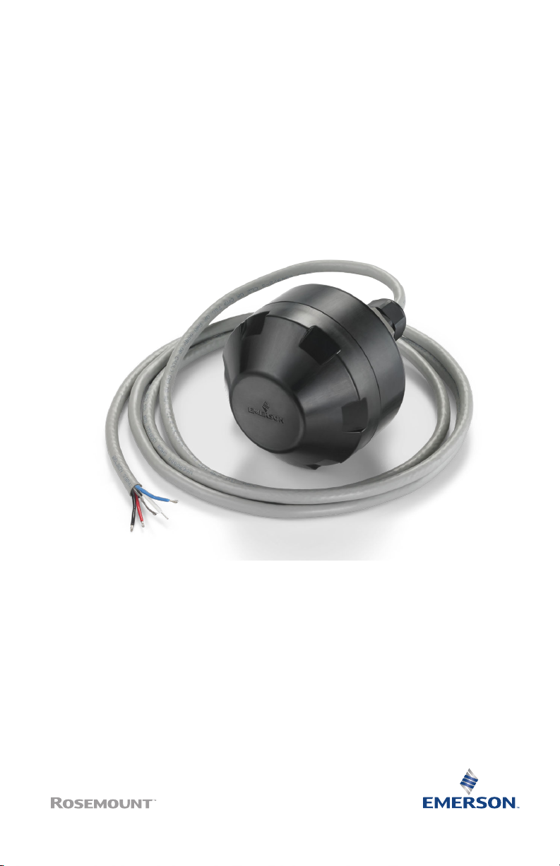
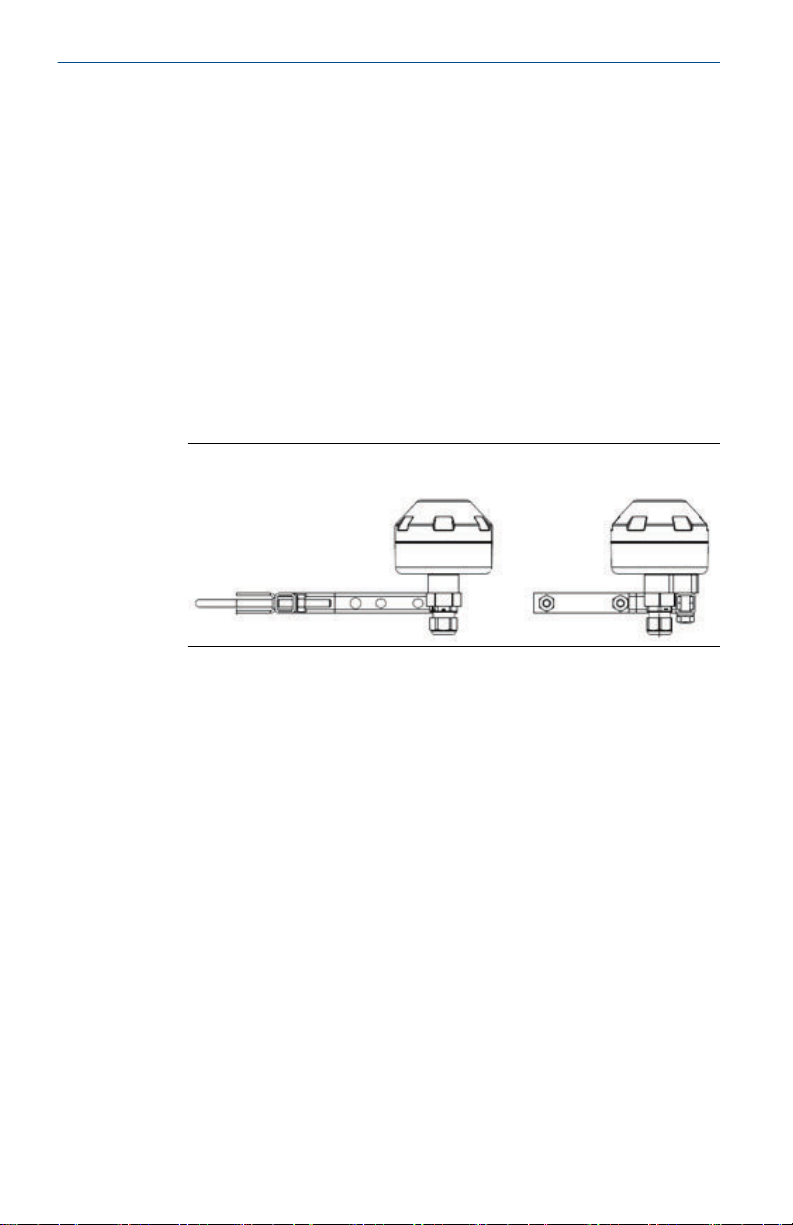
This guide provides basic guidelines for the Emerson Wireless 781S Smart Antenna. It does
not provide instructions for diagnostics, maintenance, service, or troubleshooting. Refer to
the Emerson Wireless 1410S Gateway and 781S Smart Antenna Reference Manual for more
information and instructions. The manuals and this guide are available electronically on
Emerson.com.
WARNING
Failure to follow these installation guidelines could result in death or serious injury.
Ensure only qualified personnel perform the installation.
WARNING
Explosions could result in death or serious injury.
Installation of the transmitters in a hazardous environment must be in accordance with the
appropriate local, national, and international standards, codes, and practices. Kindly review
the Product Certifications section for any restrictions associated with a safe installation.
WARNING
Electrical shock could cause death or serious injury.
Avoid contact with the leads and terminals. High voltage that may be present on leads can
cause electrical shock.
WARNING
Physical access
Unauthorized personnel may potentially cause significant damage to and/or
misconfiguration of end users’ equipment. This could be intentional or unintentional and
needs to be protected against.
Physical security is an important part of any security program and fundamental in protecting
your system. Restrict physical access by unauthorized personnel to protect end users’ assets.
This is true for all systems used within the facility.
NOTICE
This device complies with Part 15 of the Federal Communication Commission (FCC)
Rules. Operation is subject to the following conditions:
This device may not cause harmful interference.
This device must accept any interference received, including interference that may cause
undesired operation.
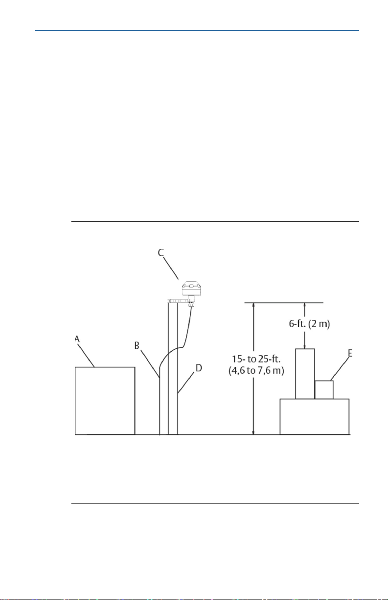
This device must be installed to ensure a minimum antenna separation distance of 8 in. (20
cm) from all persons.
Quick Start Guide July2023
2 Emerson.com

Contents
Wireless planning.........................................................................................................................5
Intended use.................................................................................................................................7
Physical installation..................................................................................................................... 8
Best practices............................................................................................................................. 11
Verify operation..........................................................................................................................12
Product certifications................................................................................................................ 13
Reference data........................................................................................................................... 24
July2023 Quick Start Guide
Quick Start Guide 3

Quick Start Guide July2023
4 Emerson.com

1 Wireless planning
1.1 Power up sequence
For a simpler and faster network installation, first install the Emerson
Wireless Smart Antenna and wireless inputs and outputs and make
sure they are functioning properly. Next, power up wireless field
devices in order of proximity from the antenna, beginning with the
closest.
1.2 Antenna location
Mount the antenna in a location that allows convenient access to the
host system network (wireless inputs/outputs) as well as the wireless
field device network.
Figure 1-1: Antenna mounting location
A. Control room
B. RS-485 cable
C. Emerson Wireless 781S Smart Antenna
D. Mast or pipe
E. Infrastructure
July2023 Quick Start Guide
Quick Start Guide 5

1.3 Antenna position
Position the Emerson 781S Smart Antenna vertically and
approximately 3 ft (1 m) from large structures, buildings, or
conductive surfaces to allow for clear communication to other
devices.
If installing multiple antennas, it is important that the antennas have
3 ft (1 m) of horizontal separation from one another.
Figure 1-2: Antenna position
Quick Start Guide July2023
6 Emerson.com

2 Intended use
2.1 System architecture
The smart antenna must be used in conjunction with a network
manager or network gateway.
The smart antenna then functions as a translator between the wired
network and a wireless field network.
Figure 2-1: Example system architecture
July2023 Quick Start Guide
Quick Start Guide 7

3 Physical installation
3.1 Mount the antenna to a pipe
Procedure
1. Insert U-bolt around 2-in. pipe or mast, through the saddle,
through the L-shaped bracket, and through the washer plate.
2. Use a ½-in. socket-head wrench to fasten the nuts to the U-
bolt.
3. Secure the antenna to the L-shaped bracket with a 5/16-in.
threaded bolt.
4. Use a 5/16-in. wrench to tighten the screw into the housing.
Figure 3-1: Mounting
3.2 Connect to power and data
The Emerson 781S is completely prewired and only needs to be
connected and powered on the Gateway end. The housing is
permanently sealed on the Emerson 781S.
Prerequisites
If operating with more than one antenna, it is important the antenna
is always connected to the antenna terminal connection 1 port.
Procedure
1. Connect the positive power lead to the “+” power terminal and
the negative power lead to the “–” terminal.
2. Connect the data + lead to the “A (+)” terminal and the data –
lead to the “B (–)” terminal.
3. Connect the grounding wire to the Gateway’s shield
connection.
Quick Start Guide July2023
8 Emerson.com

4. If connecting multiple antennas, repeat this process for
terminal connection 2.
Figure 3-2: Wiring guide
A. Power
B. Data
Red Positive
Blk (Black) Negative
Wht (White) RS-485 comm A
Blu (Blue) RS-485 comm B
Figure 3-3: Emerson Wireless 781S
A. Power output
July2023 Quick Start Guide
Quick Start Guide 9

B. RS-485 comm
Quick Start Guide July2023
10 Emerson.com

4 Best practices
Twisted shielded pair cable is generally used to wire the serial
connection to the Gateway.
Install the Smart Antenna in a central location of the wireless field
network so that it has the most direct connections to wireless devices
as possible.
July2023 Quick Start Guide
Quick Start Guide 11

5 Verify operation
5.1 Verify antenna's operation through Gateway
The antenna has no exterior lights or LCD displays. Therefore, once
it is powered up through the Gateway, you must verify its operation
through the Gateway end of the connection.
5.2 Power up sequence
The second and third LEDs in the Emerson 1410S correlate to the first
and second terminal connections. These lights should be green when
the antenna is connected properly.
5.3 Normal operation
You can assess the operation of the WirelessHART® Smart Antenna
within the Gateway user interface.
To see the connection, allow the link to be seen as a field device. To
verify operation, attempt to connect to a device.
Quick Start Guide July2023
12 Emerson.com

6 Product certifications
Rev 2.5
6.1 European Directive Information
A copy of the EU Declaration of Conformity can be found at the
end of the Quick Start Guide. The most recent revision of the EU
Declaration of Conformity can be found at Emerson.com.
6.2 Telecommunications compliance
All wireless devices require certification to ensure they adhere to
regulations regarding the use of the RF spectrum. Nearly every
country requires this type of product certification.
Emerson is working with governmental agencies around the world
to supply fully compliant products and remove the risk of violating
country directives or laws governing wireless device usage.
6.3 FCC and IC
This device complies with Part 15 of the FCC Rules. Operation
is subject to the following conditions: This device may not cause
harmful interference; this device must accept any interference
received, including interference that may cause undesired operation.
This device must be installed to ensure a minimum antenna
separation distance of 20 cm from all persons.
This device complies with Industry Canada license-exempt RSS-247.
Operation is subject to the following two conditions: (1) this
device may not cause interference, and (2) this device must accept
any interference, including interference that may cause undesired
operation of the device.
Changes or modification to the equipment not expressly approved by
Emerson could void the user's authority to operate the equipment.
Cet appareil est conforme à la Partie 15 de la réglementation
FCC. Son fonctionnement est soumis aux conditions suivantes: Cet
appareil ne doit pas causer d'interférences nuisibles. Cet appareil
doit accepter toute interférence reçue, incluant toute interférence
pouvant causer un fonctionnement indésirable. Cet appareil doit
être installé pour assurer une distance minimum de l'antenne de
séparation de 20 cm de toute personne.
Cet appareil est conforme à la norme RSS-247 Industrie
Canada exempt de licence. Son fonctionnement est soumis
aux deux conditions suivantes: (1) cet appareil ne doit pas
provoquer d'interférences et (2) cet appareil doit accepter toute
July2023 Quick Start Guide
Quick Start Guide 13

interférence, y compris les interférences pouvant causer un mauvais
fonctionnement du dispositif.
Les changements ou les modifications apportés à l'équipement qui
n'est pas expressément approuvé par Emerson pourraient annuler
l'autorité de l'utilisateur à utiliser cet équipement.
6.4 Ordinary location certification
As standard, the transmitter has been examined and tested to
determine that the design meets the basic electrical, mechanical,
and fire protection requirements by a Nationally Recognized Test
Laboratory (NRTL) as accredited by the Federal Occupational Safety
and Health Administration (OSHA).
6.5 Installing equipment in North America
The US National Electrical Code® (NEC) and the Canadian Electrical
Code (CEC) permit the use of Division marked equipment in Zones
and Zone marked equipment in Divisions. The markings must be
suitable for the area classification, gas, and temperature class. This
information is clearly defined in the respective codes.
6.6 USA
I5 USA Intrinsic Safety
Certificate 80011679
Markings Class I, II, III Division 1 Groups A, B, C, D, E, F, G T4; Class
I, II, III Division 2, Groups A, B, C, D, F, G T4 T4 (-40 °C ≤
Ta ≤ +70 °C); Class I Zone 0, AEx ia IIC T4 Ga; Class I Zone
2, AEx ic IIC T4 Gc
Standards FM 3600: 2011, FM 3610: 2018, FM 3611: 2018, ANSI/UL
60079-0: 2019, ANSI/UL 60079-11: 2014
Warnings/Conditions of Acceptability
1. Installed as per Control drawing 01410-1300 for Hazardous
and Non-Hazardous areas.
2. Must be installed with a resistive barrier.
3. The plastic enclosure may constitute a potential electrostatic
ignition risk and must not be rubbed or cleaned with a dry
cloth.
4. The measured capacitance between the equipment enclosure
and metallic conduit adapter is 21pF. This must be considered
only when the Model 781S is integrated into a system where
the process connection is not grounded.
Quick Start Guide July2023
14 Emerson.com

6.7 Canada
I6 Canada Intrinsic Safety
Certificate 80011679
Markings Class I, II, III Division 1 Groups A, B, C, D, E, F, G T4; Class
I, II, III Division 2, Groups A, B, C, D, F, G T4 T4 (-40 °C ≤
Ta ≤ +70 °C); Ex ia IIC T4 Ga; Ex ic IIC T4 Gc
Standards CAN/CSA C22.2 No 60079-0: 2019, CAN/CSA C22.2 No.
60079-11: 2014, CSA C22.2 No.213 – 2017, CSA C22.2 No.
94.2-15
Warnings
1. Installed as per Control drawing 01410-1300 for Hazardous
and Non-Hazardous areas.
2. Must be installed with a resistive barrier.
3. The plastic enclosure may constitute a potential electrostatic
ignition risk and must not be rubbed or cleaned with a dry
cloth.
4. The measured capacitance between the equipment enclosure
and metallic conduit adapter is 21pF. This must be considered
only when the Model 781S is integrated into a system where
the process connection is not grounded.
6.8 Europe
I1 ATEX/UKEX Intrinsic Safety
Certificate CSAE 21UKEX2710X, CSANe 21ATEX2301X
Markings Ex ia IIC T4 Ga (-40 °C ≤ Ta ≤ +70 °C)
Standards EN IEC 60079-0: 2018, EN 60079-11: 2012
Special Conditions for Safe Use (X):
1. Must be installed with a resistive barrier.
2. The plastic enclosure may constitute a potential electrostatic
ignition risk and must not be rubbed or cleaned with a dry
cloth.
3. The measured capacitance between the equipment enclosure
and metallic conduit adapter is 21pF. This must be considered
only when the Model 781S is integrated into a system where
the process connection is not grounded.
July2023 Quick Start Guide
Quick Start Guide 15

ATEX/UKEX Intrinsic Safety
Certificate CSAE 21UKEX4711X, CSANe 21ATEX4302X
Markings Ex ic IIC T4 Gc (-40 °C ≤ Ta ≤ +70 °C)
Standards EN IEC 60079-0: 2018, EN 60079-11: 2012
Special Conditions for Safe Use (X):
1. Must be installed with a resistive barrier.
2. The plastic enclosure may constitute a potential electrostatic
ignition risk and must not be rubbed or cleaned with a dry
cloth.
3. The measured capacitance between the equipment enclosure
and metallic conduit adapter is 21pF. This must be considered
only when the Model 781S is integrated into a system where
the process connection is not grounded.
6.9 International
I7 IECEx Intrinsic Safety
Certificate IECEx CSA 21.0052X
Markings Ex ia IIC T4 Ga (–40 °C ≤ Ta ≤ +70 °C), Ex ic IIC T4 Gc (–40
°C ≤ Ta ≤ +70 °C)
Standards IEC 60079-0: 2017, IEC 60079-11: 2011
Special Conditions for Safe Use (X):
1. Must be installed with a Resistive barrier.
2. The plastic enclosure may constitute a potential electrostatic
ignition risk and must not be rubbed or cleaned with a dry
cloth.
3. The measured capacitance between the equipment enclosure
and metallic conduit adapter is 21pF. This must be considered
only when the Model 781S is integrated into a system where
the process connection is not grounded.
6.10 Brazil
I2 INMETRO Intrinsic Safety
Certificate UL-BR 20.1568X
Markings Ex ia IIC T4 Ga (-40 °C ≤ Ta ≤ +70 °C), Ex ic IIC T4 Gc (-40
°C ≤ Ta ≤ +70 °C)
Quick Start Guide July2023
16 Emerson.com

Standards ABNT NBR IEC 60079-0: 2013, ABNT NBR IEC 60079-11:
2013
Special Conditions for Safe Use (X)
See certificate.
6.11 Japan
I4 CML Intrinsic Safety
Certificate CML20JPN2401X
Markings Ex ia IIC T4 Ga (-40 °C ≤ Ta ≤ +70 °C), Ex ic IIC T4 Gc (-40
°C ≤ Ta ≤ +70 °C)
Special Conditions for Safe Use (X)
See certificate.
6.12 Eurasian conformity
IM Intrinsic Safety
Certificate ТОО Т-Стандарт ЕАЭС KZ 7500525.01.01.00739
Markings 0Ex ia IIC T4 Ga X, 2Ex ic IIC T4 Gc X; (-40 °C ≤ Ta ≤ +70
°C)
Special Conditions for Safe Use (X)
See certificate.
6.13 China
I3 Nepsi Intrinsic Safety
Certificate GYJ21.1109X
Markings Ex ia IIC T4 Ga, Ex ic IIC T4 Gc (-40 °C ≤ Ta ≤ +70 °C)
Special Conditions for Safe Use (X)
See certificate.
6.14 Korea
IP KTL Intrinsic Safety
Certificate 21-KA4BO-0489X
Markings Ex ia IIC T4 Ga (-40 °C ≤ Ta ≤ +70 °C)
July2023 Quick Start Guide
Quick Start Guide 17

Certificate 21-KA4BO-0490X
Markings Ex ic IIC T4 Gc (-40 °C ≤ Ta ≤ +70 °C)
Special Conditions for Safe Use (X)
See certificate.
6.15 Combinations
KD Combination of I1, I5, and I6
KL Combination of I1, I5, I6, and I7
Quick Start Guide July2023
18 Emerson.com

6.16 Declaration of Conformity
Emerson Wireless 781SA Smart Antenna
July2023 Quick Start Guide
Quick Start Guide 19

Quick Start Guide July2023
20 Emerson.com
Other manuals for 781S
2
Table of contents
Other Emerson Antenna manuals
Popular Antenna manuals by other brands

Advanced Navigation
Advanced Navigation Poseidon Reference manual

Poynting
Poynting PowerfulSignal PUCK-12 user guide

MFJ
MFJ MFJ-1784 instruction manual

Televes
Televes Evoca 130990 installation manual

KVH Industries
KVH Industries TracVision M9 Replacement instructions

Spectracom
Spectracom 8230AJ installation guide

ViaSat
ViaSat 8010 Series Site Preparation Manual

Shively Labs
Shively Labs 6812B Instruction Manual Installation, Operation, & Maintenance

Belden
Belden Hirschmann BAT-ANT-N-6G-IP65 Mounting instruction

Steren
Steren ANT-9017 instruction manual

ZCG
ZCG Yagi Y200 Series installation guide

l-com
l-com HG2409Y quick start guide