Emerson Copeland Scroll User manual

Copeland Scroll™
ZXV Variable speed condensing unit for refrigeration applications
User manual

Emerson is pleased to offer the ZXV/
ZXLV variable speed condensing units
from ZX platform, especially designed for
refrigeration applications.
ZXV condensing
unit
Overall, ZX platform CDU (ZX and ZXB
medium temperature, ZXL low temperature,
ZXD/ZXLD digital modulated capacity
medium temperature and low temperature,
ZXV/ZXLV variable speed medium
temperature and low temperature
refrigeration) has been highly successful in
the Asian market and enjoys proven success
with its energy savings and customer-
friendly electronic features.

Table of contents
Disclaimer 04
Features and benefits 05
Nomenclature 05
Bill of material 05
Physical layout of the unit 06
ZXV Product specification 08
Qualified refrigerants and oils 08
Operating envelopes 08
Performance data 09
Technical data 11
CoreSense™ controller 12
Network wiring 17
Installation 19
Condensing unit handling 19
Electrical connection 19
Refrigeration piping installation 20
Liquid line insulation 20
Brazing recommendations 20
Location and fixing 21
Start up and operation 21
Vacuuming 21
Charging procedure 21
Check before starting & during operation 22
ZXV do’s and don’ts 22
Alarm codes 23
Wiring diagrams 27
Temperature sensor resistance 27
Contact lists 32

4
Disclaimer
Thank you for purchasing the ZXV condensing unit from
Emerson. ZX platform CDUs are the best in class within the
capacity and operating range available in the market. ZX CDU
is designed to operate reliably and to deliver high operating
efficiencies in medium and low temperature refrigeration
applications. It also provides constant monitoring of the
compressor operating conditions and displays the running
or fault conditions of the CDU. ZX platform CDUs have to be
installed by following the industry trade practices for its safe
and reliable operation. It is assumed that the CDU is selected,
installed and serviced only by professionals. The user manual
does not cover good industry practices which are essential on
a refrigeration equipment installation. No responsibility can be
accepted for damage caused by inexperienced or inadequately
trained site technicians or improper installation design.
If in doubt, please consult your local sales office, quoting unit
model and serial number as shown on each unit nameplate. In
case of any ambiguity, the wiring diagram supplied with each
unit takes precedence over the diagram in this manual.
Introduction to ZX platform CDU
ZX and ZXB medium temperature, ZXL low temperature, ZXD/
ZXLD digital modulated capacity medium temperature and low
temperature, ZXV/ZXLV variable speed medium temperature
and low temperature series have been highly successful in the
Asian market and enjoys proven success with its energy savings
and customer-friendly electronic features. ZX platform CDUs
have been applied by several well-known end-users and chain
retailers throughout Asia. The ZX platform is also gaining wider
acceptance in the global market and specific variants have been
developed and exported to the US, European and Middle East
markets.
Receiving your unit
All units are shipped with a holding charge of dry nitrogen
inside at a low but positive pressure. Suitable labeling is
prominently displayed on both the unit and the packaging.
Service connectors are provided on the CDU service valve for
the convenient checking of the integrity of the holding charge.
Caution! It is very important to check that this holding
pressure exists at the time you receive each unit from us or our
authorized representatives. Please inform us or our authorized
representative if the holding charge is non-existent. Failure to do
so could void the claim for other related system faults at a later
period.
Transit damage is essentially an insurance claim and is not covered
under manufacturing defect. It is also advisable to inspect the
rest of the unit for obvious physical damage and inform us or our
authorized representative in case any is discovered.
ZX platform condensing unit was designed based
on three factors demanded by industry users
Intelligent Store™solution - A most innovative approach
to enterprise facility management, Intelligent Store by Emerson
architecture integrates hardware and services, to provide
retailers a single view into their entire network of facilities
and understanding what facilities actually cost to operate and
maintain.
The Intelligent Store architecture transforms data from store
equipment and controls into actionable insights. Designed to
deliver value in both new and existing stores, Emerson aims to
help the retailers:
• Make better decisions on recourse investment for
greatest impact
• Gain accurate feedback and customized service for your
specific needs
• Reduce operational costs and boosting profitability
Energy efficiency -Utilizing Copeland Scroll™ compressor
technology, variable speed fan motor, large capacity condenser
coil and advanced control algorithms, energy consumption
is significantly reduced. End-users can save more than 20%
on annual energy costs compared to than using hermetic
reciprocating units.
Reliability - Combining the proven reliability of Copeland
Scroll compressors with advanced electronic controllers and
diagnostics, equipment reliability is greatly enhanced. Fault code
alerts and fault code retrieval capabilities provide information
to help improve speed and accuracy of system diagnostics.
Integrated electronics provide protection against over-current,
over-heating, incorrect phase rotation, compressor cycling, high
pressure resets, low pressure cut-outs. It can also send out a
warning message to an operator when there is a liquid floodback,
which can prevent critical damage on the unit.
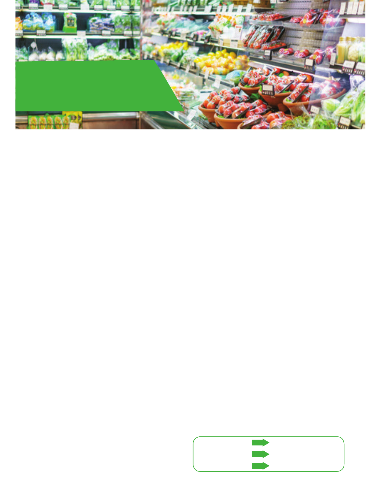
Intelligent store
Highest efficiency
Reliability
Better decision making
Lower energy bills
Lower maintenance cost
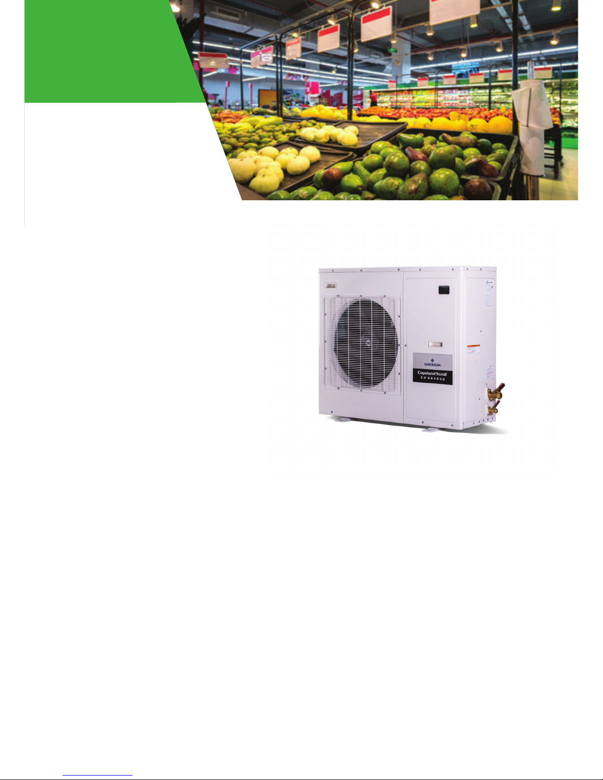
ZXV condensing unit
for refrigeration applications

5
ZX, ZXB and ZXL Family
Proprietary electronic algorithms present advantage on
diagnose, communication, and protection purposes. They
are also fundamental to control fan speed, optimizing energy
performance for local seasonal ambient temperatures
ZXD, ZXLD, ZXV Family
Capacity modulation digital and
variable speed to control precise
room or showcase temperature
Good harmonic with 3 AC chokes
Drive assembly
• High reliability with good cooling
• Easy service with quick connectors
Figure 1. ZXV CDU features
Design features:
• With real time monitoring of compressor
operating conditions
• Compressor reverse rotation
• Compressor over current
• Compressor internal motor protector trip
• Discharge gas over heat
• Over voltage
• Under voltage
• High pressure cut out
• Low pressure cut out (only on MT series)
• Refrigerant flood back
• Compressor minimum off time
• Internal thermal sensor failure
• Intelligent Store solution:
Communication and retail store
monitoring
ZXV nomenclature
Bill of material
Z X V 0 9 0 B P -4 X K 551
Condensing platform
V = Medium temp variable speed
LV = Low temp variable speed
Maximum capacity*
B = Next generation
P = R410A, POE oil
E = R404A, POE oil
Compressor motor code
K = 3 phase, 380-460V, 60Hz
D = 3 phase, 380-400V, 50Hz
Bill of material
451 = Chassis with hinged door
551 = Chassis with front panel
Base model Electrical code Bill of material
ZXV BOM ZXV ZXLV
451, 551 451, 551
Liquid line filter drier
Moisture indicator
Oil separator
Accumulator
Suction pressure transducer
Fixed hp switch
Fixed lp switch
CoreSense™ & Intelligent Store
Fan speed control
Circuit breaker
Sound jacket
Optimized condenser coil for
maximum heat transfer
Variable speed fan motor and high
efficiency fan blade
Copeland Scroll compressor technology
High efficiency, ultra quiet, high reliability
Enhanced vapor injection
• Improved efficiency
• Combined DLT protection
Note: *Maximum capacity condition of evap temp/amb temp/return gas temp
Medium temp -10°C/40°C/18.3°C
Low temp -32°C/40°C/5°C

6
Physical layout of the unit
The following figures give an introduction to the physical layout of the ZXV CDU
Variable speed driver
Capacitor board
EMI Filter board
CoreSense™
Humidity indicator
Choke
Variable speed driver
Oil separator
Liquid receiver
Liquid filter drier
Plate heat exchanger
Suction and liquid service valve
Suction pressure transducer
Compressor oil sight glass
Receiver out service valve
Figure 2. ZXV CDU layout
Figure 3. Drive assembly layout

7
Capacitor board
Contactor Customer connection
terminal block
Transformer
CoreSense™
Figure 5. CoreSense™ controller
Figure 4. Control box layout
H-K:
Hot-key
connection
port
EV:
EXV connection
port
485:
RS485
connection
port
VNR:
Remote display
connection
port
D13:
LP Switch
connection
port
A12-A17:
Temp sensor
connection
ports
Al1:
Pressure
transducer
connection
ports
Supply:
Power supply connection
port (24VAC from
transformer)
Current
transformer holes
User interface
R-S-T:
Voltage
measurement
connector
TO1:
Triac output 1
(Fan motor
connecter)
TO2:
Triac output
2 (Digital valve
connecter)
Neutral:
Common terminal
connector (TFD/PFJ/TF7:
neutral;TF5: common
terminal)
Dl1:
Unit on/off
control
D04:
Crankcase
heater
connector
C2:
HP Switch
input
connection
D03:
Driver power supply contactor output
connector
D01/D02/C1:
Reserved connector
D05:
Alarm dry contact
output connector
Power isolation switch

8
ZXV product specication
Qualified refrigerants and oils
Medium temperature
Low temperature
Refrigerant Oil
R410A/R404A Emkarate RL 32 3 MAF / Mobil EAL Artic 22 CC
Oils are pre-charged in both compressor and oil separator.
Operating envelopes
Ambient temperature (0C)Ambient temperature (0C)
Ambient temperature (0C)
48
43
10
48
43
10
48
43
10
Evaporating temperature (0C)
ZXV R410A
Return gas temp 18.3°C
ZXLV R404A
Return gas temp 5°C
ZXV R404A
Return gas temp 18.3°C
Limited running (1)
Limited running (1)
Limited running (1)
-15
-40
-20
Note: (1) Continue run but with speed limitation
-10
-30
-15-5
-20
-100
-10
-510 55
0
0
ZXV090BP

9
Model
Ambient
tempera-
ture (°C)
Evaporating temperature (°C)
-15 -10 -5 0 5 10
Min Nor Max Min Nor Max Min Nor Max Min Nor Max Min Nor Max Min Nor Max
ZXV075BP
Capacity (kW)
27 2.93 5.01 7.50 3.57 5.96 8.67 4.18 6.86 10.04 4.84 7.55 10.82 5.40 8.31 11.57 6.00 8.93 12.62
32 2.83 4.84 7.12 3.48 5.74 8.49 4.05 6.63 9.73 4.74 7.29 10.70 5.25 8.03 11.29 5.85 8.65 12.27
38 2.73 4.70 7.19 3.39 5.54 8.51 3.87 6.44 9.78 4.53 7.18 10.89 5.10 7.83 11.35 5.70 8.45 12.18
43 2.65 4.57 6.92 3.27 5.33 8.12 3.76 6.23 9.51 4.35 7.00 10.62 4.95 7.55 11.08 5.55 8.24 11.82
Power (kW)
27 1.22 2.00 3.33 1.27 2.14 3.52 1.25 2.23 3.76 1.28 2.43 4.08 1.29 2.51 4.31 1.30 2.64 4.56
32 1.36 2.22 3.64 1.42 2.32 3.87 1.42 2.47 4.12 1.45 2.70 4.53 1.50 2.82 4.90 1.55 2.94 5.15
38 1.56 2.50 4.34 1.64 2.74 4.77 1.65 2.80 5.07 1.68 2.97 5.43 1.76 3.07 5.70 1.82 3.25 5.97
43 1.77 2.87 4.98 1.84 3.11 5.42 1.88 3.14 5.61 1.88 3.37 5.88 1.91 3.56 6.15 1.96 3.68 6.42
ZXV090BP
Capacity (kW)
27 2.93 7.30 8.44 3.57 8.68 9.75 4.18 9.99 11.29 4.84 11.00 12.18 5.40 12.10 13.01 8.00 13.00 14.20
32 2.83 7.04 8.01 3.48 8.36 9.55 4.05 9.66 10.95 4.74 10.62 12.03 5.25 11.70 12.70 7.80 12.60 13.80
38 2.73 6.84 7.79 3.39 8.06 9.22 3.87 9.37 10.60 4.53 10.46 11.80 5.10 11.40 12.30 7.60 12.30 13.20
43 2.65 6.65 7.50 3.27 7.76 8.80 3.76 9.08 10.30 4.35 10.20 11.50
Power (kW)
27 1.22 3.26 3.94 1.27 3.49 4.17 1.25 3.63 4.46 1.28 3.97 4.83 1.29 4.10 5.10 1.30 4.30 5.40
32 1.36 3.62 4.32 1.42 3.78 4.58 1.42 4.03 4.88 1.45 4.40 5.37 1.50 4.60 5.80 1.55 4.80 6.10
38 1.56 4.07 4.80 1.64 4.46 5.27 1.65 4.57 5.60 1.68 4.84 6.00 1.76 5.00 6.30 1.82 5.30 6.60
43 1.77 4.68 5.50 1.84 5.08 6.00 1.88 5.12 6.20 1.88 5.50 6.50
R410A
Note:
• The rating condition is based on a return gas temperature of 18.3°C.
• Power includes condenser fan.
• Ambient 38°C and 43°C are typical design conditions for unit selection.
Performance data

10
Model
Ambient
tem-
perature
(°C)
Evaporating temperature (°C)
-20 -15 -10 -5 0 5
Min Nor Max Min Nor Max Min Nor Max Min Nor Max Min Nor Max Min Nor Max
ZXV065BE
Capacity (kW)
27 1.81 4.66 5.94 2.23 5.46 6.85 2.70 6.47 8.23 3.20 7.49 8.23 3.76 8.32 10.11 4.32 8.78 10.06
32 1.67 4.41 5.68 2.13 5.29 6.62 2.58 6.20 7.87 3.09 7.22 7.87 3.63 8.03 9.75 4.18 8.48 9.74
38 1.57 4.16 5.31 1.93 4.97 6.36 2.41 5.89 7.48 2.98 6.88 7.48 3.48 7.48 9.09 3.99 7.76 8.89
43 1.44 3.88 5.05 1.86 4.77 6.14 2.27 5.55 6.75 2.84 6.53 6.75 3.25 7.04 8.64 3.66 7.25 8.49
Power (kW)
27 0.88 2.16 2.96 0.87 2.31 3.18 0.87 2.35 3.35 0.89 2.55 3.56 0.91 2.70 3.80 0.92 2.91 4.24
32 0.98 2.38 3.24 0.99 2.54 3.44 0.99 2.59 3.64 0.99 2.81 3.95 1.02 3.00 4.28 1.04 3.25 4.85
38 1.13 2.70 3.62 1.13 2.86 3.87 1.13 2.89 4.11 1.14 3.14 4.41 1.18 3.35 4.75 1.22 3.62 5.35
43 1.24 3.03 4.04 1.26 3.19 4.30 1.29 3.24 4.57 1.29 3.50 4.86 1.31 3.66 5.15 1.33 3.91 5.71
ZXV085BE
Capacity (kW)
27 2.29 5.91 7.53 2.83 6.91 8.68 3.42 8.20 10.42 4.05 9.49 10.42 4.76 10.54 12.80 5.47 11.12 12.74
32 2.11 5.59 7.20 2.70 6.70 8.38 3.27 7.85 9.97 3.91 9.15 9.97 4.60 10.17 12.35 5.29 10.74 12.34
38 1.99 5.28 6.73 2.45 6.30 8.06 3.05 7.47 9.47 3.77 8.72 9.47 4.41 9.48 11.52 5.05 9.84 11.26
43 1.83 4.92 6.40 2.35 6.04 7.78 2.88 7.03 8.55 3.60 8.27 8.55 4.12 8.92 10.94 4.64 9.19 10.75
Power (kW)
27 1.12 2.83 3.99 1.10 3.02 4.29 1.10 3.08 4.52 1.13 3.33 4.80 1.15 3.53 5.12 1.17 3.79 5.71
32 1.24 3.11 4.37 1.25 3.32 4.63 1.26 3.39 4.90 1.26 3.68 5.32 1.29 3.92 5.77 1.32 4.24 6.53
38 1.43 3.53 4.88 1.43 3.74 5.22 1.43 3.78 5.54 1.45 4.10 5.94 1.50 4.37 6.40 1.55 4.73 7.20
43 1.57 3.96 5.44 1.60 4.17 5.79 1.64 4.24 6.16 1.64 4.57 6.55 1.66 4.79 6.94 1.68 5.10 7.70
R404A
Note:
• The rating condition is based on a return gas temperature of 18.3°C.
• Power includes condenser fan.
• Ambient 38°C and 43°C are typical design conditions for unit selection.
Performance data

11
Note:
• The rating condition is based on a return gas temperature of 5°C.
• Power includes condenser fan.
• Ambient 38°C and 43°C are typical design conditions for unit selection.
Model
Am-
bient
temp
(°C)
Evaporating temperature (°C)
-40 -35 -30 -25 -20 -15 -10 -5 0
Min Nor Max Min Nor Max Min Nor Max Min Nor Max Min Nor Max Min Nor Max Min Nor Max Min Nor Max Min Nor Max
ZXLV
030BE
Capacity (kW)
27 0.79 1.86 2.50 0.94 2.40 3.16 1.21 2.93 3.87 1.45 3.84 5.02 1.75 4.52 5.77 2.17 5.29 6.65 2.62 6.28 7.98 3.10 7.26 9.11 3.65 8.07 9.80
32 0.73 1.82 2.38 0.92 2.30 3.01 1.15 2.86 3.70 1.39 3.69 4.82 1.62 4.28 5.51 2.07 5.13 6.42 2.50 6.01 7.63 2.99 7.00 8.75 3.52 7.78 9.46
38 0.71 1.72 2.27 0.87 2.22 2.89 1.10 2.67 3.61 1.36 3.55 4.63 1.52 4.04 5.15 1.88 4.82 6.17 2.34 5.72 7.25 2.89 6.67 8.37 3.38 7.26 8.82
43 0.66 1.65 2.17 0.84 2.11 2.74 1.06 2.60 3.39 1.29 3.35 4.38 1.40 3.77 4.90 1.80 4.63 5.96 2.21 5.38 6.55 2.76 6.33 7.90 3.16 6.83 8.38
Power (kW)
27 0.84 1.79 2.33 0.85 1.90 2.46 0.86 2.00 2.33 0.86 2.05 2.40 0.89 2.17 2.98 0.87 2.32 3.20 0.87 2.37 3.37 0.90 2.56 3.58 0.91 2.71 3.82
32 0.94 1.99 2.64 0.95 2.05 2.74 0.95 2.19 2.60 0.95 2.29 2.71 0.98 2.39 3.26 0.99 2.56 3.45 1.00 2.61 3.65 1.00 2.83 3.97 1.02 3.01 4.30
38 1.08 2.28 3.10 1.09 2.36 3.18 1.09 2.53 3.00 1.07 2.59 3.07 1.13 2.71 3.64 1.13 2.88 3.89 1.13 2.91 4.13 1.15 3.16 4.43 1.19 3.36 4.77
43 1.22 2.63 3.54 1.23 2.67 3.66 1.25 2.83 3.36 1.25 2.94 3.48 1.25 3.04 4.06 1.27 3.21 4.32 1.30 3.26 4.59 1.30 3.52 4.89 1.32 3.68 5.18
ZXLV
040BE
Capacity (kW)
27 1.00 2.36 3.17 1.19 3.04 4.00 1.53 3.71 4.90 1.83 4.86 6.36 2.22 5.73 7.30 2.75 6.70 8.42 3.32 7.95 10.11 3.93 9.20 11.54 4.62 10.2212.42
32 0.92 2.31 3.02 1.16 2.91 3.81 1.46 3.63 4.69 1.76 4.68 6.11 2.05 5.42 6.98 2.62 6.49 8.13 3.17 7.61 9.67 3.79 8.87 11.09 4.46 9.86 11.98
38 0.90 2.18 2.88 1.10 2.82 3.67 1.39 3.38 4.58 1.72 4.50 5.86 1.93 5.12 6.53 2.38 6.11 7.82 2.96 7.24 9.19 3.66 8.45 10.60 4.28 9.20 11.17
43 0.83 2.09 2.75 1.07 2.67 3.47 1.34 3.30 4.30 1.63 4.24 5.55 1.78 4.77 6.21 2.28 5.86 7.55 2.79 6.82 8.29 3.49 8.02 10.01 4.00 8.65 10.61
Power (kW)
27 1.07 2.34 3.15 1.08 2.48 3.32 1.09 2.62 3.15 1.09 2.67 3.24 1.13 2.84 4.01 1.11 3.03 4.31 1.11 3.09 4.54 1.14 3.35 4.82 1.16 3.54 5.15
32 1.19 2.60 3.56 1.21 2.67 3.70 1.21 2.86 3.51 1.21 2.99 3.65 1.25 3.12 4.39 1.26 3.34 4.65 1.27 3.40 4.92 1.27 3.69 5.35 1.30 3.93 5.80
38 1.37 2.98 4.18 1.39 3.08 4.29 1.38 3.30 4.04 1.36 3.38 4.14 1.44 3.54 4.90 1.44 3.76 5.25 1.44 3.80 5.57 1.46 4.12 5.97 1.51 4.39 6.43
43 1.55 3.44 4.76 1.56 3.49 4.93 1.59 3.69 4.52 1.59 3.84 4.68 1.58 3.97 5.47 1.61 4.19 5.82 1.65 4.26 6.19 1.65 4.59 6.58 1.67 4.81 6.97
Performance data R404A

12
Technical data
Medium temperature
Low temperature
Family ZXV
Model name ZXV075BP ZXV090BP ZXV065BE ZXV085BE
Refrigerant R410A R404A
Evap temperature range °C -15°C ~ 10°C -20°C ~ 5°C
Ambient range °C -25°C ~ 48°C
Perfor-
mance
Maximum capacity -10°C ET/40°C
AT/18°C RGT kW 7.5 9.0 6.5 8.5
Nominal capacity -10°C ET/32°C
AT/18°C RGT
kW 5.7 8.4 6.1 7.9
Nominal COP W/W 2.45 2.21 2.44 2.32
Nominal speed RPM 3000 RPM 4500 RPM 4500 RPM 4500 RPM
Compres-
sor
Model name ZBW030DP-4X9 ZBW030DP-4X9 ZBW030DE-4X9 ZBW038DE-4X9
Max input ampere Amp 15 22 15 22
Oil type Amp POE POE POE POE
Oil charge volume Liters 1.63 1.63 1.63 1.63
Speed range RPM 1800 - 4800 1800 - 5400 1800 - 6000 1800 - 6000
Fan
motor
Number of fan 1 1 1 1
Diameter mm 450 450 450 450
Max speed RPM 933 933 933 933
Max flow Total m3/h 3483 3483 3483 3483
Max fan motor power Input W145 145 145 145
Others
Oil seperator Volume Liters 0.5 0.5 0.5 0.5
Receiver volume kg 4.3 4.3 4.3 4.3
Pipes Suction OD Inch 3/4 3/4 3/4 3/4
Liquid OD Inch 1/2 1/2 1/2 1/2
Dimension W X H X D mm 1029 x 424 x 840 1029 x 424 x 840 1029 x 424 x 840 1029 x 424 x 840
Weight Net kg 101 101 101 104
Gross kg 139 139 139 139
Family ZXLV
Model name ZXLV030BE ZXLV040BE
Refrigerant R404A
Evap temperature range °C -40°C ~ 0°C
Ambient range °C -25°C ~ 48°C
Performance
Maximum capacity -32°C ET/40°C
AT/5°C RGT kW 3.20 4.10
Nominal capacity -32°C ET/32°C
AT/5°C RGT
kW 2.64 3.34
Nominal COP W/W 1.24 1.20
Nominal speed RPM 4500 RPM 4500 RPM
Compressor
Model name ZFW030DE-4X9 ZFW038DE-4X9
Max input ampere Amp 15 22
Oil type Amp POE POE
Oil charge volume Liters 1.63 1.63
Speed range RPM 1800 - 6000 1800 - 6000
Fan motor
Number of fan 1 1
Diameter mm 450 450
Max speed RPM 933 933
Max flow Total m3/h 3483 3483
Max fan motor power Input W145 145
Others
Oil seperator Volume Liters 0.5 0.5
Receiver volume kg 4.3 4.3
Pipes Suction OD Inch 3/4 3/4
Liquid OD Inch 1/2 1/2
Dimension W X H X D mm 1029 x 424 x 840 1029 x 424 x 840
Weight Net kg 101 104
Gross kg 139 139

13
Keyboard descriptions - single button
Set Display target set point; In programming mode, select a parameter or confirm an operation.
Start
Reset Hold for 5 seconds to reset any lockouts if the current state of the controller allows for it to be
reset.
Up Enter the fast access menu; In programming mode, browse the parameter codes or increases
the displayed value.
Down In programming mode it browses the parameter codes or decreases the displayed value.
Service Enter the service and alarm menu.
Defrost Hold for 3 seconds to start a manual defrost or terminate an active defrost.
(Not available at the moment).
LED descriptions
LED Status Description
1
ON Compressor1 is running
Flashing Compressor1 is ready to start
2
ON Reserved
Flashing Reserved
ON Condensing fan is running
ON Reserved
ON Display with °C
Flashing Programmable mode
LED Status Description
ON Browsing the service menu
Flashing Browsing the fast access menu
!
ON A new alarm happened
Flashing Browsing the alarm menu
!ON An alarm is occurring
ON Reserved
-Reserved
CoreSense™controller

14
Keyboard descriptions - combined buttons
+Press and hold for about 3 seconds to lock (Pon) or unlock (PoF) the keyboard.
+Pressed together to exit programming mode or menu; under rtC and Par, this combination allows the user to go
back to previous level.
+Pressed together for 3 seconds allows access to first level of programming mode.
+Pressed together for 3 seconds allows access to EXV manual setting.
Controller initialization message
When the unit is initially powered on, the controller will display.
Step Action Phenomenon and Description
1 Power on controller All LEDs will light up for 3 seconds.
2Firmware version will be displayed for 3 seconds.
3Parameter setting file (bin file number) identifier will be displayed for 3 seconds.
4Normal display (actual suction temperature will be displayed on ZXV/ZXD unit, condensing
temperature will be displayed on ZX/ZXL/ZXB unit)

15
Bin files number range
Step Action Phenomenon and description
1Press “ ” + “ ” Enter menu to select “PAr” (parameter) or “rtC”
2Press “ ” or “ ” Select“PAr (parameter)”
3Press “ ”Confirm selection
4Press “ ” or “ ” Browse to parameter C07
5Press “ ”Confirm selection
6Press “ ” or “ ” Select refrigerant to be used
7Press “ ”The number will flash for 3 seconds and confirm the refrigerant selection
8Press “ ” + “ ” Exit (or exit automatically after waiting for 120 seconds)
Step Action Phenomenon and description
1Press “ ” + “ ” Enter menu to select “PAr” (parameter) or “rtC”
2Press “ ” or “ ” Select “rtC”
3Press “ ”
“n01” , minute
“n02” , hour
“n03” , day
“n04” , month
“n05” , year (last two digits)
4Press “ ”Display actual value
5Press “ ” or “ ” Modify the value
6Press “ ”Press“SET” : the value will flash for 3 seconds, then move to the next value
7Press “ ” + “ ” Exit to “rtC”
8Press “ ” + “ ” Exit to main menu (or wait for 120 seconds and exit automatically)
After installation and initial power on, it is critical to double check the parameters below.
Refrigerants
Bin number range Family
701-799 ZXV, ZXLV
850 ZXV service
851 ZXLV service
Step Action Phenomenon and description
1Press “ ” > 3 seconds Press “ ” button for more than 3 seconds, the measurement units (°C ) will flash
together.
2Press “ ” or “ ” Modify the number for target evaporating temperature
3Press “ ”Press “ ” to confirm, the number will flash for 2 seconds (or wait for about 10
seconds to confirm)
Evaporating temperature setting
RTC (real time clock) setting

16
Quick access menu browse - sensors status and actual values
Step Action Phenomenon and description
1Press “ ” Enter quick access menu, will display“P1P”(Press “Up” or “Down” to view other sensors
2Press “ ”View the actual value of “P1P”
3Press “ ”Change to next sensor code
4Press “ ” + “ ” Exit (or exit automatically after waiting for 60 seconds)
Sensor code and values descriptions
(“nP”, “noP”, or“nA” mean that the
sensor does not exist; “Err” means that
the sensor fails, out of range,
disconnected, or does not configure
correctly)
• P1P : Pressure value of suction(Only in ZXD & ZXV)
• P2t : Temperature value of condenser mid coil
• P2P : Pressure value of discharge(not used)
• P3t : Temperature value of DLT(discharge line temperature)
• P4t : Temperature value of VIT(vapor inlet temperature) (only in ZXL, ZXV, ZXB)
• P5t : Temperature value of VOT(vapor outlet temperature) (Only in ZXL, ZXV, ZXB)
• P6t : Temperature value of ambient temperature
• P7t : Not used
• SH : Value of superheat when control logic control vapour injection superheating,
or display DLT values when control logic is control DLT
• oPP : Percentage of step EVI valve opening
• LLS : Status of the liquid line solenoid (not used)
• Std : Value of the condenser temperature setting
• Aoo : Percentage of condensing fan driver output
• dSo : Percentage of the PWM output driving the valve of the Digital Scroll
compressor (not used)
• inU : Compressor speed percentage of controller sent to driver (only in ZXV)
• inS : Compressor speed percentage of the reading values from driver(only in ZXV)
• iUt : Driver input voltage values(only in ZXV)
• iPr : Driver input power values(only in ZXV)
• Lt : Minimum room temperature(not used)
• Ht : Maximum room temperature(not used)
• tU1 : Voltage 1(R-S terminal) values(not used)
• tU2 : Voltage 2(S-T terminal) values(not used)
• tU3 : Voltage 3(T-R terminal) values(not used)
• tA1 : Current 1(upper transformer) values(not used)
• tA2 : Current 2(lower transformer) values(not used)
• HM : Time Menu(hour & minute)
Pr1 parameter (1st level) browse and modification
Step Action Phenomenon and description
1Press “ ” + Enter menu to select “PAr” (parameter) or “rtC”
2Press “ ” or “ ” Select “PAr (parameter)”
3Press “ ”Confirm, select, and browse Pr1 parameters
4Press “ ” or “ ” Browse Pr1 parameters
5Press “ ”View the actual number of the Pr1 parameters
6Press “ ” or “ ” Modify the actual number of the Pr1 parameters
7Press “ ”Press“SET” : The number will flash for 3 seconds and confirm the modification; Will go
to the next Pr1 parameter
8Press “ ” + Exit (or exit automatically after waiting for 120 seconds)

17
Exact timing of the alarm
Upload the program from the controller to hot-key
Step Action Phenomenon and description
1Press “ ” Display “SEC”
2Press “ ”Display “A01”
3Press “ ”Display alarm code in “A01”
4Press “ ”Display “Hr”
5Press “ ”Display the alarm exact timing: hour
6Press “ ”Display “Min”
7Press “ ”Display the alarm exact timing: minute
8Press “ ”Display “dAy”
9Press “ ”Display the alarm exact timing: day
10 Press “ ”Display “Mon”
11 Press “ ”Display the alarm exact timing: month
12 Press “ ”Display “yEA”
13 Press “ ”Display the alarm exact timing: year
14 Press “ ” + “ ” Exit (or exit automatically after waiting for 15 seconds)
Step Action Phenomenon and description
1Inert Hot-Key when the
controller is ON
2Press “ ”
the “uPL” message appears followed by a flashing “End” label
(Note: if display “Err”, it means it fails to upload program to Hot-Key.
Please restart the process.)
3Press “ ”“End” will stop flashing
4Turn-off the controller
and remove Hot-Key
5 Turn-on the controller
Access alarm code (maximum of 50 record)
Step Action Phenomenon and description
1Press “ ”Display “SEC”
2Press “ ”Display “A01”
3Press “ ”Display alarm code in “A01”
4Press “ ”Display “A02”
5Press “ ”Display alarm code in “A02”
6…
7Press “ ” + “ ” Exit (or exit automatically after waiting for 15 seconds)

18
Network wiring
Dixell XWEB300D serial address
• Connect to the ModBUS network using cable with 2 or 3 shielded wires, minimum section 0.5mm2
(e.g. BELDEN8772)
• Do not connect shield to ground.
• Do not connect the “Gnd” terminal.
• Remember to draw a map of the line. This will help you to find an error if something is wrong.
• RS485 devices are polarity sensitive.
Figure 5. Correct network wiring
Figure 6 . Incorrect network wiring
Download the program from hot-key to controller
Step Action Phenomenon and description
1 Turn-off the controller
2 Insert hot-key
3 Turn-on the controller The “doL” message will blink followed a by a flashing “End” label (Note: if display “Err”,
it means it fails to download program to the controller. Please restart the process.)
4 Controller will restart working with the new parameters after 10 seconds
5Remove hot-key

19
ZX CDU connected to XWEB300D
Figure 7. XWEB300D Connected to the Intelligent Store solution module
Dixell XWEB300D configuration
XWEB300D is compatible with ZX CDU if XWEB has the library of ZX controller CoreSense.
Login into XWEB
• Go to Information → Information
• If this is not present, follow the steps below.
Open Dixell website http://www.dixell.com/xweb300d-xweb500-xweb500d/eng/, then login (registration required)
• Go to Support → System sw update → XWEB300D XWEB500 XWEB500D
• Download the upgrade package with your web-browser, login into XWEB
• Go to Information → System Update menu
Provide the XW5 patch file
Once file has been selected wait until the upgrade procedure ends (XWEB reboots)
Verify the installation ended successfully by checking into the menu
• Go to Information → Information for string
Log in again and set up the ZX CDU
• Go to Configuration → Devices drop-down menu
• Go to Actions → New
• Enter device name in the Name field (e.g. ZX CDU)
• Select “XCM25D” in the Model field
• Enter the ModBUS address in the RS 485 address field
∙ Refer to setting of parameter “t01” in pr2 level in CoreSense™(default setting is “1”)
• Click New
Termination resistor for XWEB300D
If XWEB300D is placed at the beginning or at the end of
the line, please install its termination resistor by adding
a jumper in position 2 (JMP2 on the back side of the
unit). Do not add the jumper if XWEB300D is placed in
the middle of the RS485 line.
ZX CDU connected to the Dixell XWEB300D with the Intelligent Store
solution module using RS485 ModBUS.
Connect the ZX CDU to the ModBUS network as shown in Figure 7. Connect
the network cable to the three-terminal connector on the XWEB300D port
that has been configured as ModBUS port (COM 12, 13, 14).
Connect port “13” of XWEB300D to port “D0485 +” of CoreSense™and port
“12” of XWEB300D to port “D1485 -” of CoreSense
for RS485 communication.

20
Installation
Electrical connection
Power supply
The ZXV condensing unit electrical connection to the power supply must be made by qualified technicians, who should refer to the
electrical diagrams located inside the electric connection panel. The units are designed for below power supply at ± 10% voltage
tolerance. The circuit breaker must be switched off before opening the front panel.
Electrical wiring
Before commissioning, ensure that neutral “N” wire is connected to the terminal block (“N” furthest to the right). After proper
connection of the ZXV condensing unit, the control LED on the power board and control board will light up. For more details, see wiring
diagrams. Customers’ wire size needs to be selected to allow for the maximum operation current of each unit.
Caution! Unit should be powered on at all times except during service. Failure to do so can result in component failure.
Copeland ZX condensing units are delivered with a holding charge of neutral gas. The condensing unit should be located in a place
protected from excess amounts of dirt, sand, dust, plastic bags, leaves or paper debris which can cover and block the flow of air over
the condenser (fins). The unit must be installed without restricting the airflow. A clogged condenser will result in increased condensing
temperature, reducing the cooling capacity, causing the high-pressure switch to trip. Clean the condenser fins on a regular basis.
Condensing unit handling
Transport and storage
Move ZXV unit only with appropriate mechanical or handling equipment according to weight. Keep in the upright position. Do not stack
single boxes on top of each other without pallet in any case. Keep the packaging dry at all times.
Other manuals for Copeland Scroll
4
Table of contents
Popular Commercial Food Equipment manuals by other brands

Tecfrigo
Tecfrigo SNELLE 501 G Installation and use manual

Hoshizaki
Hoshizaki KS0-4G Use and installation manual

croydon
croydon F1AB instruction manual

AHT
AHT MACAO 100 operating instructions

Bourgeat
Bourgeat NAV'THERM Instructions for use and maintenance

Lotus
Lotus BM-94G Instructions for installation and use

KBS
KBS TP-12/E Installation, operation and maintenance instructions

FWE
FWE PHU Series operating instructions

Kelvinator
Kelvinator KCHUC23F Service, installation and care manual

Crown
Crown ECTS-12 Installation & operation manual

Cornelius
Cornelius HELIX Operator's manual

Casselin
Casselin CTV300 operating instructions