Emerson 781 User manual

ReferenceManual
00809‐0200‐xxxx,RevAA
April2010
SmartWirelessFieldLink
Start
WirelessConsiderations
Step1:PhysicalInstallation
Step2:VerifyOperation
ReferenceInformation
OrderingInformation
Specifications
ProductCertifications
ECDeclarationofConformity
End

ReferenceManual
00809‐0200‐xxxx,RevAA
April2010
www.emersonprocess.com
©2009RosemountInc.Allrightsreserved.Allmarkpropertyofowner.
EmersonProcessManagement
RosemountDivision
8200MarketBoulevard
Chanhassen,MNUSA55317
T(US)(800)999‐9307
T(INTL)(952)906‐8888
F(952)949‐7001
EmersonProcessManagement
AsiaPacificPrivateLimited
1PandanCrescent
Singapore128461
T(65)67778211
F(65)67770947/(65)67770743
Notice
Warning
Failure to follow these installation guidelines could result in death or serious injury:
•Make sure only qualified personnel perform the installation.
Explosions could result in death or serious injury:
•Installation of this transmitter in an explosive environment must be in accordance
with the appropriate local, national, and international standards, codes, and
practices. Please review the Product Certifications section for any restrictions
associated with a safe installation.
Electrical shock can result in death or serious injury
•Avoid contact with the leads and terminals. High voltage that may be present on
leads can cause electrical shock.
•This device complies with Part 15 of the FCC Rules. Operation is subject to the
following conditions.
•This device may not cause harmful interference. This device must accept any
interference received, including interference that may cause undesired operation.
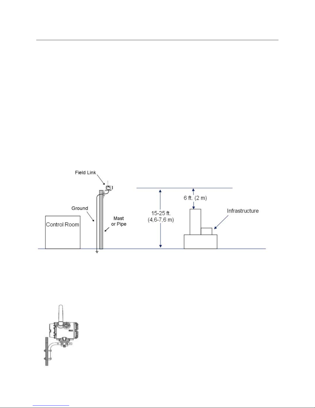
•This device must be installed to ensure a minimum antenna separation distance
of 8 in. (20 cm) from all persons.
Read this manual before working with the product. For personal and system safety, and for
optimum product performance, make sure you thoroughly understand the contents before
installing, using, or maintaining this product.
Within the United States, Emerson Process Management has the following toll-free
assistance numbers:
Global Service Center
Software and Integration Support
1-800-833-8314 (United States)
+63-2-702-1111 (International)
North American Response Center
Equipment service needs.
1-800-654-7768 (24 hours – includes Canada)

ReferenceManual
00809‐0200‐xxxx,RevAA
April2010
WirelessConsiderations
PowerUpSequence
TheSmartWirelessFieldLinkandWirelessI/Oshouldbeinstalledandfunctioningproperlybeforethepower
modulesareinstalledinanywirelessfielddevices.Wirelessfielddevicesshouldalsobepoweredupinorderof
proximityfromtheFieldLinkbeginningwiththeclosest.Thiswillresultinasimplerandfasternetworkinstallation.
MountingLocation
TheFieldLinkshouldbemountedinalocationthatallowsconvenientaccesstothehostsystemnetwork(wireless
I/O)aswellasthewirelessfielddevicenetwork.
FindalocationwheretheFieldLinkhasoptimalwirelessperformance.Ideallythiswillbe15‐25ft.(4,6‐7,6m)
abovethegroundor6ft.(2m)aboveobstructionsormajorinfrastructure.
Figure1.MountingLocation
AntennaPosition
Theantennashouldbepositionedvertically,eitherstraightuporstraightdown,andshouldbeapproximately3ft.
(1m)fromanylargestructure,building,orconductivesurfacetoallowforclearcommunicationtootherdevices.
Figure2.AntennaPosition

ReferenceManual
00809‐0200‐xxxx,RevAA
April2010
ConduitPlug
Thetemporaryorangeplugsshouldbereplacedwiththeconduitplugsthatareincludedusingapprovedthread
sealant.
Figure3.
ConduitPlugs
IntendedUse
TheFieldLinkmustbeusedinconjunctionwithanetworkmanagerornetworkgateway.TheFieldLinkthen
functionsasatranslatorbetweenthewirednetworkandawirelessfieldnetwork.
Figure4.ExampleSystemArchitecture

ReferenceManual
00809‐0200‐xxxx,RevAA
April2010
STEP1:PhysicalInstallation
PipeMounting
1. InsertlargerU‐boltaround2”pipe/mast,throughthesaddle,throughtheLshapedbracket,andthrough
thewasherplate.
2. Usea½‐insocket‐headwrenchtofastenthenutstotheU‐bolt.
3. InsertsmallerU‐boltaroundbasetheFieldLinkandthroughtheLshapedbracket.
4. Usea½‐insocket‐headwrenchtofastenthenutstotheU‐bolt.
Figure5.Mounting
PowerandDataWiring
1. Removehousingcoverlabeled“FieldTerminals.“
2. Connectthepositivepowerleadtothe“+”powerterminalandthenegativepowerleadtothe“‐”
terminal.
3. ConnecttheData+leadtothe“A(+)”terminalandtheData–leadtothe“B(‐)”terminal.
4. Plugandsealanyunusedconduitconnections.
5. Replacethehousingcover.
Figure6.SmartWirelessFieldLinkTerminalDiagram
Note:Thisdevicehasbeendesignedwithdouble/reinforcedinsulationbetweenthepowerterminals
andthehousing.

ReferenceManual
00809‐0200‐xxxx,RevAA
April2010
Grounding
TheFieldLinkenclosureshouldalwaysbegroundedinaccordancewithnationalandlocalelectricalcodes.The
mosteffectivegroundingmethodisadirectconnectiontoearthgroundwithminimalimpedance.Groundthe
FieldLinkbyconnectingtheexternalgroundlugtoearthground.Theconnectionshouldbe1Ωorless.
STEP2:VerifyOperation
Addlocaldisplayscreenshere.
Power‐UpSequence
UponapplyingpowertotheFieldLinktheLCDmeterwillactivateanddisplayaseriesofstartupscreen.The
followingscreensaredisplayedduringstartup.
1. StartupScreen1–Allsegmentson
2. StartupScreen2–DeviceIdentification
3. StartupScreen3–Tag
4. StartupScreen4–Status
NormalOperation
AftertheinitialstartupscreenstheFieldLinkwillcyclethroughseveralperiodicscreens.
1. ElectronicsTemperatureScreen
2. PercentRangeScreen
3. WiredInterfaceUsage
4. RadioInterfaceUsage
Thefieldlinkwillcontinuetorotatethrougheachperiodicscreenthroughthecourseofnormal
operation.Ifanydiagnosticorfaultconditionoccurs,acorrespondingdiagnosticsscreenwillappear.

ReferenceManual
00809‐0200‐xxxx,RevAA
April2010
ReferenceInformation
Figure7.SmartWirelessFieldLinkTerminalDiagram
Note:
TheSmartWirelessFieldLinkrequiresseparatetwistedshieldpairs(4wires)forpoweranddata
DataA
(
+
)
DataB
(
‐
)
Return
+24 Volts

ReferenceManual
00809‐0200‐xxxx,RevAA
April2010
Figure8.SmartWirelessFieldLinkDimensionalDrawing
Specifications
Table1.SmartWirelessFieldLinkSpecifications
Item Specification
Input Power 10.5 – 30 VDC,
Operating Temperature -40 to 185 °F (-40 to 85 °C)
Wiring to WirelessHART I/O Terminal Block 18 AWG Twisted Shield Pairs
Wiring Distance 656 ft (200 m)
Wireless Protocol WirelessHART, 2.4-2.5 GHz DSSS
Wireless Output Power, EIRP 10 dBm (10 mW) Long Range Antenna Option WK
12.5dBm (17mW) Extended Range Antenna Option WM
Mounting All SST, 2 in. Pipe and Panel Mount Bracket
Humidity 0-90% relative humidity

ReferenceManual
00809‐0200‐xxxx,RevAA
April2010
OrderingInformation
Table2.SmartWirelessFieldLinkOrderingInformation
Model ProductDescription
781 SmartWirelessFieldLink
PhysicalConnection
Standard Standard
A1 RS485 *
Housing
Standard Standard
D DualCompartmentHousing‐Aluminum *
E DualCompartmentHousing‐StainlessSteel *
ConduitThreads
Standard Standard
1 1/2‐14NPT *
2 M20 *
ProductCertifications
Standard Standard
I5 FMIntrinsicallySafe,Non‐incendive *
I6 CSAIntrinsicallySafe *
I1 ATEXIntrinsicallySafe *
I7 IECExIntrinsicSafet
y
*
KL FM&CSAClass1Division1,ATEXZone0IntrinsicallySafe *
NA NoApprovals *
WirelessUpdateRate,OperatingFrequencyandProtocol
Standard Standard
WA3 UserConfigurableUpdateRate,2.4GHzDSSS,WirelessHART *
OmnidirectionalWirelessAntennaandSmartPower
Standard Standard
WK3 ExternalAntenna,LinePower10‐30VDC *
WM3 ExtendedRange,ExternalAntenna,LinePower10‐30VDC *
Options
Meter
StandardStandard
M5LCDMeter*
GlandandConnectorOptions
StandardStandard
G2CableGland(7.5mm‐11.9mm)*
G4ThinWireCableGland(3mm‐8mm) *
TypicalModelNumber:781A1D1KLWA3WK3M5

ReferenceManual
00809‐0200‐xxxx,RevAA
April2010
ProductCertifications
ApprovedManufacturingLocations
RosemountInc.–Chanhassen,Minnesota,USA
EmersonProcessManagementAsiaPacificPrivateLimited–Singapore
TelecommunicationsCompliance
AllwirelessdevicesrequirecertificationtoensurethattheyadheretoregulationsregardingtheuseoftheRF
spectrum.Nearlyeverycountryrequiresthistypeofproductcertification.Emersonisworkingwithgovernmental
agenciesaroundtheworldtosupplyfullycompliantproductsandremovetheriskofviolatingcountrydirectivesor
lawsgoverningwirelessdeviceusage.
FCCandIC
ThisdevicecomplieswithPart15oftheFCCRules.Operationissubjecttothefollowingconditions.Thisdevice
maynotcauseharmfulinterference.Thisdevicemustacceptanyinterferencereceived,includinginterferencethat
maycauseundesiredoperation.Thisdevicemustbeinstalledtoensureaminimumantennaseparationdistanceof
20cmfromallpersons.
OrdinaryLocationCertificationforFM
Asstandard,theGatewayhasbeenexaminedandtestedtodeterminethatthedesignmeetsbasicelectrical,
mechanical,andfireprotectionrequirementsbyFM,anationallyrecognizedtestinglaboratory(NRTL)as
accreditedbytheFederalOccupationalSafetyandHealthAdministration(OSHA).
NorthAmericanCertifications
I5FMDivision1,IntrinsicallySafe,Non‐Incendiveandxxx
CertificateNumber:XXXXXXX
XXXXXXXXXX
XXXXXXXXX
I6CSADivision1,IntrinsicallySafe
CertificateNumber:XXXXXXX
XXXXXXXXXX
XXXXXXXXX

ReferenceManual
00809‐0200‐xxxx,RevAA
April2010
EuropeanUnionDirectiveInformation
TheECdeclarationofconformityforallapplicableEuropeandirectivesforthisproductcanbefoundonthe
Rosemountwebsiteatwww.rosemount.com.Ahardcopymaybeobtainedbycontactingyourlocalsales
representative.
ATEXDirective(94/9/EC)
EmersonProcessManagementcomplieswiththeATEXDirective.
ElectroMagneticCompatibility(EMC)(2004/108/EC)
EmersonProcessManagementcomplieswiththeEMCDirective.
RadioandTelecommunicationsTerminalEquipmentDirective(R&TTE)(1999/5/EC)
EmersonProcessManagementcomplieswiththeR&TTEDirective
EuropeanCertification
I1ATEXIntrinsicSafety
CertificateNumber:XXXXXXXXXXX
XXXXXXXXXXXXXXXXXXX
XXXXXXXXXXXXXXXXXXXX
I7IECExIntrinsicSafety
CertificateNumber:XXXXXXXX
XXXXXXXXXXXXXXXXXXXXXXXX
XXXXXXXXXXXXXXXXXXXXX

ReferenceManual
00809‐0200‐xxxx,RevAA
April2010
Figurex.ECDeclarationofConformityforSmartWirelessFieldLink
[InsertECDeclarationofConformityhere]
Other manuals for 781
1
Table of contents
Other Emerson Extender manuals

Emerson
Emerson Fisher SS-263 User manual

Emerson
Emerson Fisher SS-263 User manual

Emerson
Emerson Avocent HMX Installation and maintenance instructions

Emerson
Emerson Avocent LongView 3000 Series User manual

Emerson
Emerson Load Bus Sync User manual

Emerson
Emerson fisher VBL User manual

Emerson
Emerson LongView LV1000 KVM User manual

Emerson
Emerson Fisher 2625 User manual
Popular Extender manuals by other brands

LEGRAND
LEGRAND C2G30011 manual

Intercoax
Intercoax ETP-01 SeriesETP-01T quick start guide

Extron electronics
Extron electronics DTP HDMI 330 Setup guide

Paradyne
Paradyne SNE2000G Errata

Guntermann & Drunck
Guntermann & Drunck CATVision-USB 2.0 installation guide

iBall
iBall generation i iB-WRR312N user manual