Instruction Manual
D103628X012
CVX Blowdown Fixture
June 2017
4
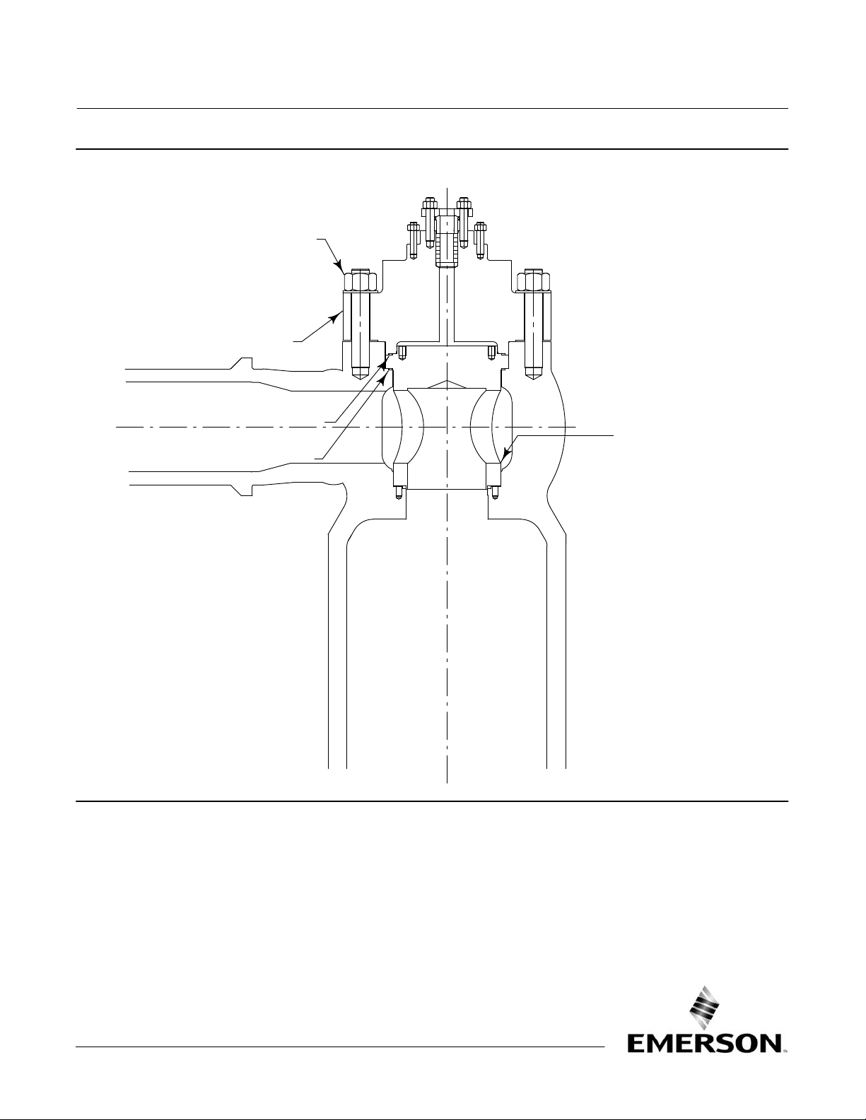
4. Inspect the bonnet guiding surfaces and gasket mating surfaces. Light damage on the guiding surface may be
repaired with an emery cloth or other suitable material. Damage to the gasket mating surface may require bonnet
replacement to avoid leakage.
5. Remove the plug assembly (key 22, 23, and 53) as a single unit by grasping the valve stem (key 23) and pulling the
assembly from the body cavity. The plug assembly contains sensitive guiding and sealing surfaces on its outside
diameter and care must be taken in its handling. The plug should be temporarily stored on a clean wooden or cloth
surface.
6. Remove the cage (key 21) from the valve body. Remove and discard the upper and lower cage gaskets (key 43).
Reference the CVX valve instruction manual for guidance in performing this disassembly. The cage contains
sensitive guiding surfaces on its outside diameter and care must be taken during handling. The cage should be
temporarily stored on a clean wooden or cloth surface.
7. Clean and inspect the guiding and sealing surfaces of the plug assembly. For balanced plug designs, inspect the
piston ring (key 45) and Bore Seal ring (key 46) for signs of excess wear or damage and replace if necessary. The
piston ring is a two piece design with an outer seal ring and an inner expander ring. The outer ring diameter should
be expanded beyond the diameter of the plug in its free state. It can be shifted within its groove to inspect for
uneven wear around its circumference. The piston ring should require some compression when installing the plug
into the cage. Lack of required compression indicates that the piston ring has worn or relaxed and should be
replaced. Vertical marks in the axial orientation also indicates wear that requires replacement of the ring. The Bore
Seal ring has a C‐shaped cross section with the open portion of the C‐shape facing the stem side of the plug for
flow‐up designs and the open portion of the Cshape facing the seating surface of the plug for flowdown designs.
Any uneven marks around the circumference of the ring or any flattening of the ring shape at its outside diameter
are indications of wear and require replacement. Contact your Emerson sales office or Local Business Partner for
Bore Seal ring replacement.
8. Clean and inspect the inside diameter surfaces of the cage. The entire length of the cage inside diameter is either a
sealing and/or guiding surface and any measurable wear requires that the cage be replaced.
9. Bolted Seat Ring Removable Diffuser Only: The bolted seat ring and seat diffuser must be removed. Loosen the seat
ring bolts, (key 76) using an even and opposing pattern (for example, if the first nut loosened is at the 1 o'clock
position, the next nut to be loosened would be at the 7 o'clock position). This will prevent uneven loading of the
seat ring studs, which may cause binding. Individual bolts should not be completely loosened while the remaining
bolts are tight. It is suggested that at least two stages of loosening be used to avoid overloading the last few
remaining studs. Reference the CVX instruction manual for guiding on removing the bolted seat ring and seat
diffuser (key 77). Discard lower diffuser gaskets (key 75). The bolted seat ring and seat diffuser contain sensitive
guiding and gasket surfaces on its outside diameter and care must be taken in their handling. The seat ring and seat
diffuser should be temporarily stored on a clean wooden or cloth surface.
10. Remove all used gaskets and foreign matter from the interior of the valve and from the inlet and outlet openings.
Remove any foreign matter that may be in the valve trim. Inspect all valve body guiding and sealing surfaces for any
signs of wear.
Visual Inspection
Visually inspect the interior of the valve for abnormal wear, signs of erosion, or scoring if the valve has been in service.
All scores and scratches should be removed by grinding or filing to remove any interference of the clearance zones
between the internal bores and the mating parts. The affected area should be sanded with 100 grit or finer paper. Do
not attempt to completely remove the score, only the interference should be removed and sanded.
The gasket surfaces of the valve body and bonnet should be inspected to verify that they are not damaged and are free
of imbedded gasket material.