manuals.online logo
Brands
  1. Home
  2. •
  3. Brands
  4. •
  5. Emerson
  6. •
  7. Switch
  8. •
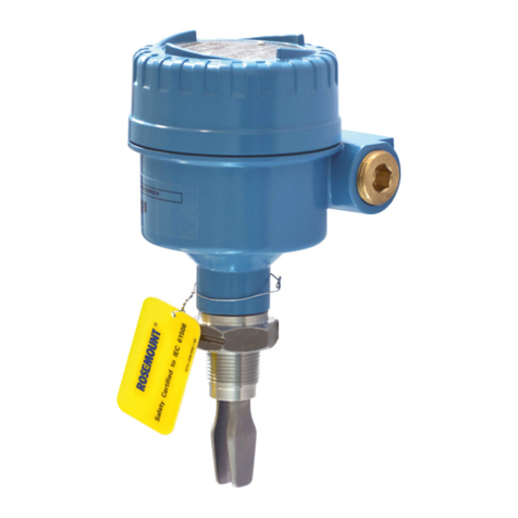
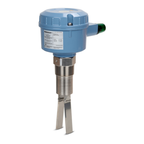
  9. Emerson Rosemount 2140 User manual

Emerson Rosemount 2140 User manual

Other manuals for Rosemount 2140

4

Other Emerson Switch manuals

Emerson Rosemount 2410 User manual

Emerson

Emerson Rosemount 2410 User manual

Emerson ASCO 300 Series User manual

Emerson

Emerson ASCO 300 Series User manual

Emerson Rosemount 2130 User manual

Emerson

Emerson Rosemount 2130 User manual

Emerson Alco Controls PS1 Series User manual

Emerson

Emerson Alco Controls PS1 Series User manual

Emerson Penberthy MGS-314 Series Manual

Emerson

Emerson Penberthy MGS-314 Series Manual

Emerson Rosemount 2110 User manual

Emerson

Emerson Rosemount 2110 User manual

Emerson SC885 User manual

Emerson

Emerson SC885 User manual

Emerson Rosemount 2535 User manual

Emerson

Emerson Rosemount 2535 User manual

Emerson mobrey squing 2 User manual

Emerson

Emerson mobrey squing 2 User manual

Emerson DWM COPELAND OPS2 Manual

Emerson

Emerson DWM COPELAND OPS2 Manual

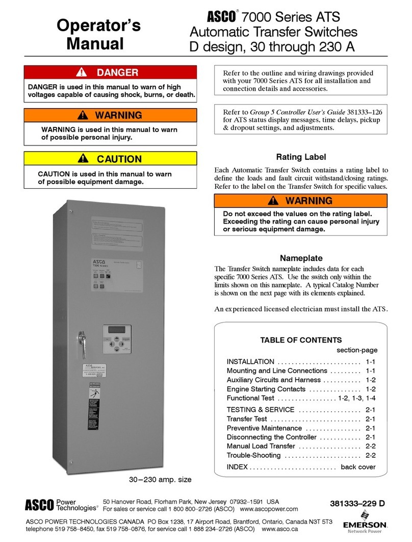
Emerson ASCO 7000 Series User manual

Emerson

Emerson ASCO 7000 Series User manual

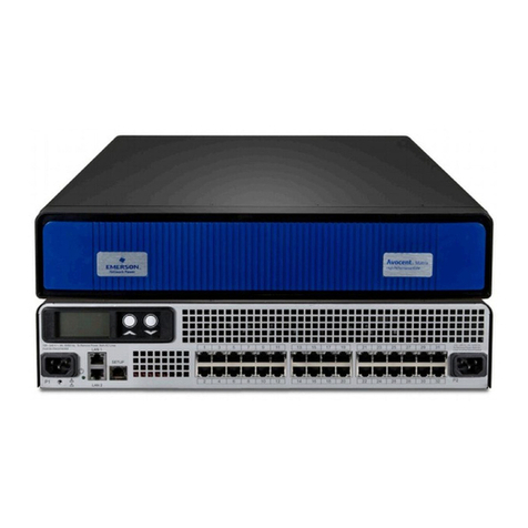
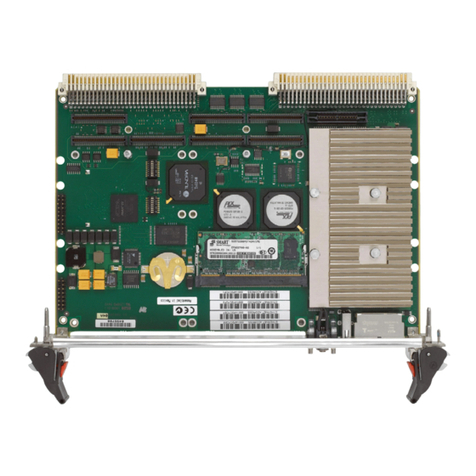
Emerson MVME4100ET User manual

Emerson

Emerson MVME4100ET User manual

Emerson Rosemount 2521 Series User manual

Emerson

Emerson Rosemount 2521 Series User manual

Emerson ASCO 300 Series User manual

Emerson

Emerson ASCO 300 Series User manual

Emerson LRA185KMM User manual

Emerson

Emerson LRA185KMM User manual

Emerson Avocent SV 220D User manual

Emerson

Emerson Avocent SV 220D User manual

Emerson Rosemount 2110 User manual

Emerson

Emerson Rosemount 2110 User manual

Emerson AVOCENT User manual

Emerson

Emerson AVOCENT User manual

Emerson PACSystems SLM042 User manual

Emerson

Emerson PACSystems SLM042 User manual

Emerson Rosemount 2410 Configuration guide

Emerson

Emerson Rosemount 2410 Configuration guide

Emerson PACSystems SLM080 User manual

Emerson

Emerson PACSystems SLM080 User manual

Emerson Rosemount 2120 User manual

Emerson

Emerson Rosemount 2120 User manual

Emerson Avocent SV 220 User manual

Emerson

Emerson Avocent SV 220 User manual

Emerson Liebert STS2 User manual

Emerson

Emerson Liebert STS2 User manual

Popular Switch manuals by other brands

SMC Networks SMC6224M Technical specifications

SMC Networks

SMC Networks SMC6224M Technical specifications

Aeotec ZWA003-S operating manual

Aeotec

Aeotec ZWA003-S operating manual

TRENDnet TK-209i Quick installation guide

TRENDnet

TRENDnet TK-209i Quick installation guide

Planet FGSW-2022VHP user manual

Planet

Planet FGSW-2022VHP user manual

Avocent AutoView 2000  AV2000BC AV2000BC Installer/user guide

Avocent

Avocent AutoView 2000 AV2000BC AV2000BC Installer/user guide

Moxa Technologies PT-7728 Series user manual

Moxa Technologies

Moxa Technologies PT-7728 Series user manual

Intos Electronic inLine 35392I operating instructions

Intos Electronic

Intos Electronic inLine 35392I operating instructions

Cisco Catalyst 3560-X-24T Technical specifications

Cisco

Cisco Catalyst 3560-X-24T Technical specifications

Asante IntraCore IC3648 Specifications

Asante

Asante IntraCore IC3648 Specifications

Siemens SIRIUS 3SE7310-1AE Series Original operating instructions

Siemens

Siemens SIRIUS 3SE7310-1AE Series Original operating instructions

Edge-Core DCS520 quick start guide

Edge-Core

Edge-Core DCS520 quick start guide

RGBLE S00203 user manual

RGBLE

RGBLE S00203 user manual

Thrustmaster FLIGHT SIMULATOR X quick guide

Thrustmaster

Thrustmaster FLIGHT SIMULATOR X quick guide

Southwire SURGE GUARD 41390 RVC troubleshooting guide

Southwire

Southwire SURGE GUARD 41390 RVC troubleshooting guide

Buhler Nivotemp NT 61 Brief instructions

Buhler

Buhler Nivotemp NT 61 Brief instructions

Kramer VS-41HDCP user manual

Kramer

Kramer VS-41HDCP user manual

Techly IDATA AU-270 user manual

Techly

Techly IDATA AU-270 user manual

Belkin F1U109 user manual

Belkin

Belkin F1U109 user manual

manuals.online logo
manuals.online logoBrands
  • About & Mission
  • Contact us
  • Privacy Policy
  • Terms and Conditions

Copyright 2025 Manuals.Online. All Rights Reserved.

Quick Start Guide
00825-0100-4140, Rev AA
January 2017
Quick Start Guide for Installation
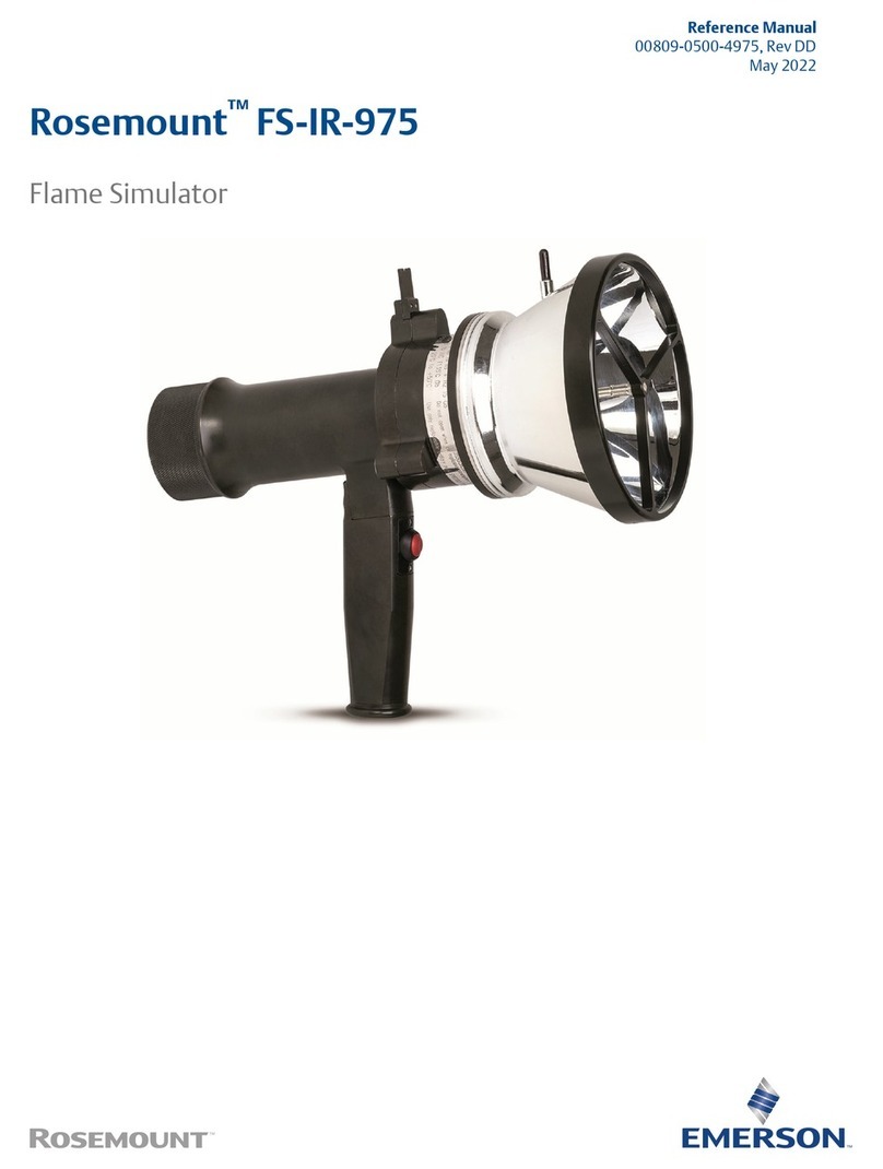
Rosemount™2140 Level Detector
Vibrating Fork
January 2017
2
Quick Start Guide
1.0 About this guide
This Quick Start Guide provides basic guidelines for Rosemount 2140 and
2140:SIS Vibrating Fork Liquid Level Detectors (“level detectors”).
Refer to the Rosemount 2140 Reference Manual for more instructions, and the
Rosemount 2140 Product Certifications Manual for approvals information and
safety matters. Manuals are available electronically at Emerson.com/Rosemount.
1.1 Symbols used in this guide
1.2 Required equipment
Standard tools e.g. screwdrivers and wire strippers/cutters.
1.3 Contents
Failure to follow safe installation guidelines could result in death or serious injury.
Use the level detector only as specified in this guide and the product reference manual.
The level detector must be installed, connected, commissioned, operated, and maintained by suitably
qualified personnel only, observing national and local requirements that may apply.
The weight of a level detector with a heavy flange and extended fork length may exceed 37 lb. (18 kg).
A risk assessment is required before carrying, lifting, and installing the level detector.
Explosions could result in death or serious injury.
Refer to the Rosemount 2140 Product Certifications Manual for restrictions associated with the
intrinsically safe, explosion-proof/flameproof and dust approvals for this product.
Electrical shock could cause death or serious injury
Make sure that the level detector is not powered when removing the terminal cover and
making terminal connections.
If the level detector is installed in a high voltage environment and a fault condition or installation error
occurs, high voltage may be present on leads and terminals.
External surfaces may be hot.
Care must be taken to avoid possible burns. The flange and process seal may be hot at high process
temperatures. Allow to cool before servicing.
Refer to the Rosemount 2140 Reference Manual for further
information.
Adobe®Acrobat®Reader software is needed to view the
document contents.
Switch off power (0) to the level detector.
Switch on power (1) to the level detector.
Installation . . . . . . . . . . . . . . . . . . . . . . . . . . . . . . 3
Adjust display orientation (optional) . . . . . . . . 7
Prepare the electrical connections . . . . . . . . . . 8
Connect wiring and power up . . . . . . . . . . . . . . 9
Confirm system readiness . . . . . . . . . . . . . . . . 14
Configure level detector using Guided Setup 14
www
Quick Start Guide
3
January 2017
2.0 Installation
2.1 Mounting the threaded version
Step 1: Seal and protect the threads
Use anti-seize paste or PTFE tape according to your site procedures.
Step 2: Mount the level detector on tank or pipework
Threaded tank or pipework connection (vertical installation)
Threaded tank or pipework connection (horizontal installation)
Gasket may be used as a sealant
for BSPP (G) threaded connections.
Gasket (for BSPP (G) threaded connection)
Tighten using the
hexagon only
Gasket (for BSPP (G)
threaded connection)
Tighten using the
hexagon only
January 2017
4
Quick Start Guide
Threaded flange connection
1. Place the customer supplied flange on the tank nozzle.
2. Tighten the bolts and nuts with sufficient torque for the flange and gasket.
3. Screw the level detector into the flange thread.
Gasket (customer supplied)
Gasket for BSPP (G) threads only
Quick Start Guide
5
January 2017
2.2 Mounting the flanged version
Step 1: Lower the level detector into the nozzle
Step 2: Tighten the bolts and nuts
Gasket (customer supplied)
January 2017
6
Quick Start Guide
2.3 Mounting the Tri Clamp version
Step 1: Lower the level detector onto the flange face
Step 2: Fit the Tri Clamp
Seal (supplied with Tri Clamp)
Quick Start Guide
7
January 2017
3.0 Adjust display orientation (optional)
To improve field access to wiring or get a better view of the optional LCD display:
1. Loosen the set screw until the level detector housing can rotate smoothly.
a. Do not unscrew all the way. Rotating the housing, without this screw in
place, can damage the internal wiring.
2. First, rotate the housing clockwise to the desired location.
If the desired location cannot be achieved due to the internal thread limit, rotate
the housing counterclockwise.
3. Re-tighten the set screw.
H3/32 in.
Torque 30 in-lb (3 Nm)
Do not attempt to rotate the display
beyond the thread limits.
January 2017
8
Quick Start Guide
4.0 Prepare the electrical connections
4.1 Cable selection
Use 24-14 AWG wire. Twisted-pairs and shielded wiring is recommended for
environments with high EMI (electromagnetic interference). Two wires can be
safely connected to each terminal screw.
4.2 Cable gland/conduit
For intrinsically safe, explosion-proof/flameproof, and dust-proof installations,
use the supplied blanking plug and a suitably certified cable gland/conduit entry
device(s).
4.3 Power supply
The level detector operates on 10.5 - 42.4 Vdc (10.5 - 30 Vdc in intrinsically safe
installations) at the level detector terminals.
4.4 Power consumption
Maximum of 1 W, current maximum 23 mA.
4.5 Load limitations
For HART®communication, a minimum load resistance of 250 Ù is required.
The maximum loop resistance is determined by the voltage level of the external
power supply, as described in Figure 1.
Figure 1. Load Limitations
Maximum Loop Resistance = 43.5 * (External Power Supply Voltage - 10.5)
0
External Power Supply Voltage (Vdc)
200
Loop Resistance (Ohms)
400
600
800
1000
1200
1400
10 20 30 40 40
24 42.4
10.5
250
1392
848
587
16.3
Quick Start Guide
9
January 2017
5.0 Connect wiring and power up
Step 1: Remove the cover
Step 2: Remove the plastic plugs
Step 3: Pull the cable through the cable gland/conduit
Verify that the power supply is disconnected or switched off.
½-14 NPT M20 x 1.5
M20(No marking)
Identification of
thread size and type
Use a suitably rated cable, and
cable gland/conduit entry device.
January 2017
10
Quick Start Guide
Step 4: Connect the cable wires
Figure 2. 4-20 mA/HART®Communication
A. Field Communicator (IS approved for intrinsically safe installations)
B. Approved IS barrier (for intrinsically safe installations only)
C. HART modem
D. Load resistance (250 Ù)
E. Current meter
F. Power supply
Torque 7 in-lb (0.8Nm)
-+
-
+
Fn
123
456
789
0-
.
A
BD
E
F
C