emitor Combolook Color HD User manual

Combolook
Color HD
User Manual
Sjöviksbacken 14
, 4 tr
SE-117 43 Stockholm, Sweden
Phone: +4 (0)8 775 00 01
Fax: +4 (0)8 775 00 0
www.emitor.se
Combolook Color HD

2
Thank You for purchasing the Emitor AB Combolook Color HD instrument.
This manual covers the operation and maintenance of the Emitor AB
Combolook Color HD instrument used for satellite dish alignment, T and
CAT alignment and signal analysis.
All information in this publication is based on the latest product information
available at the time of printing.
Emitor AB reserves the right to make changes at any time without notice and
without incurring any obligation.
No part of this publication may be reproduced without written permission.
This manual should be considered a permanent part of the instrument and
should remain with it if the instrument is resold.
If a problem should arise, or if you have any questions about the instrument,
consult an authorized Emitor AB dealer.
Notice
Notice Notice
Notice
Operating the Combolook Color HD instrument requires special skills.
Please read this User Manual thoroughly before operating the instrument.
Updated: July 19, 2010

3
Contents
Overview 3
Unpacking 6
Operating Controls 6
LCD 8
Remote Control 9
Satellite Instrument Mode 10 - 23
Spectrum Operation (Satellite) 10
Digital Mode (Satellite) 12
Digital Mode Functions (Satellite) 13
Digital Picture Mode (Satellite) 14
Analog Picture Mode (Satellite) 16
Memory Operation (Satellite) 17
Text Editor (Satellite) 17
DiSEqC (Satellite) 18
Setup (Satellite) 19
Special Functions (Satellite) 20
UniCable LNB Functions (Satellite) 22
T Instrument Mode 24 - 33
Spectrum Operation (T ) 24
Analog Picture Mode (T ) 26
Memory Operation (T ) 28
Digital Picture Mode (T ) 29
Setup (T ) 31
Signal-to-Noise Ratio Measurements (T ) 32
Channel Power Measurement (T ) 33
Using PC to Transfer Transponder Data 34
Loading Firmware 35
Appendix A – Universal LNB Primer 37
Appendix B – DiSEqC Primer 38
Appendix C – D B-S and D B-S2 Primer 40
Appendix D – UniCable Primer 41
Appendix E– Television Channel Tables 44
Appendix F – D B-T Principles 52
Appendix G – Maintenance 53
Appendix H – Specifications 54
Glossary 55

4
Overview
The Emitor Combolook Color HD is a Swedish designed Satellite T /CAT instrument
and spectrum analyzer. The unit was designed for the exact alignment and adjustment of
satellite dishes, terrestrial antennas, as well as trouble-shooting and quality control of
MDU systems layout including CAT networking.
This instrument was designed for the professional when accurate and precise information
is needed. With ease of operation through powerful processor technology, basic
operation is achieved with only a few controls. The functions are easy to access and only
take minutes to learn. Many functions can be controlled by the enclosed Remote
control.
A 5 inch 16:9 color TFT-LCD display is provided which shows either normal “Free to air”
satellite T channels in Analog or D B-S, CAT Analog and Digital channels, the
frequency spectrum or a Constellation diagram and digital information regarding the
signal.
Menus and help displays are shown on the LCD screen (64x128) beside the monitor and a
keypad is used for the function selection. The knob is used for frequency and other
operations. A remote control is provided which allows most of the keypad commands to
be used to control the instrument.
The Combolook functions as both an instrument for use in Satellite and terrestrial T or
CAT . The mode of operation is selected at power on, and to conserve battery life only
the necessary functions are enabled. Switching modes can be done at power on or by
menu selection.
Satellite Instrument Mode
The Spectrum shown enables the measurement of the satellite spectrum in resolution
steps of 1 MHz to 10 MHz making it easy for the skilled installer to know what satellite
he is receiving and make more detailed measurements. The Spectrum function spans the
frequency band 920-2150 MHz and can be expanded from 4 MHz down to 1 MHz steps.
Automatic frequency conversion to the user defined LNB type is shown on screen so no
calculations are needed to determine the Satellite frequency. Cross polarization at a
frequency can be easily checked with the cross polarization function. The instrument has
high resolution for accuracy. It presents measured data ±2 dB (at 20
o
C). Frequency
tuning is done with the main knob in frequency steps between 4 MHz and 1 MHz
depending on the span of the spectrum. When the spectrum is displayed, Automatic
Spectrum Identification is provided by accessing the NIT information by hunting for a
D B-S signal from one of the transponders. The Analog Picture mode can display a
multistandard PAL, NTSC and SECAM picture and accepts audio frequencies between 5.5
and 8.5 MHz. Analog pictures can be viewed either directly using the spectrum as a
guide, or recalled from 100 user defined memory positions.
The Digital Mode shows extended information of Modulation, SIG, SNR, BER, MER, and a
constellation diagram. The Satellite Name and position are shown using the Network
Information Table in the MPEG transport stream. Channel detail (or Service Information)
can also be displayed for a transponder if needed.

5
The user memory positions can save spectrum displays, analog channels, digital channels
and Saved spectrum positions can be mixed simultaneously with an actual reading for
easy comparison and control of signal-levels. Measurements on group of channels can
be made with up to 10 frequencies simultaneously with automatic polarization and band
selection.
For Universal LNBs, the polarisation /H is switchable by 13/18 and Lo/Hi band with 22
kHz-tone.
The instrument features circuitry protection to prevent short circuits during connection
of the LNB.
The DiSEqC function controls all DiSEqC accessories such as switches and positioners.
T Instrument mode
The Spectrum is shown from 2MHz to 900MHz and can be zoomed to smaller segments
(minimum 13MHz span) for closer inspection. In T mode, it presents measured data ±1
dB (at 20
o
C). The Combolook
Color HD is capable of working with the return-path
signals in Cable-T networks (5-65 MHz) according to the EN50083 standard. Signal to
Noise measurements and Digital Channel power measurements can be made using
Reference markers on the spectrum.
Analog T pictures can be displayed with sound and attenuation inserted from 0-45dB to
determine picture quality with increased attenuation. T Channels can be saved as
favorites for easy tuning.
D B-T MPEG-2 digital transmissions can be viewed to check signal quality.
The Combolook Color HD is powered by a built- in, rechargeable Li-Ion battery. The
battery can be recharged using either the included external battery charger or the car-
adaptor.
The Combolook Color HD weighs less than 4kg including the battery and the carrying
case.
6
Unpacking
Unpack the instrument and check that the following items are included:
1. Combolook Color HD instrument.
2. Nylon carrying case with shoulder strap.
3. Power supply and charger 110-230 AC /14 DC, center pin positive
4. Auto Adapter cord (Car charger) 12 .
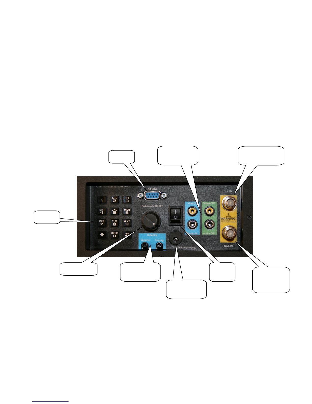
Operating Controls
The side view of the Combolook Color HD is shown below with the operating
controls indicated.
Power Switch
Power SwitchPower Switch
Power Switch)
))
) On battery power, this turns the instrument on and off. When the charger
is connected, the instrument will charge with the switch off, and operate when on. The
instrument will not charge when operating.
Charger Power
Charger PowerCharger Power
Charger Power Input)
Input) Input)
Input) The instrument can be charged or operated using either the
supplied 14 power supply or from a 12 car cigarette lighter plug using the supplied
connector.
Keypad)
Keypad)Keypad)
Keypad) This is used to select most of the functions from the menu.
Keypad
Video and
Audio Output
Audio Volume
and Tuning
RS232
Power
Switch RF Input
from NB
for Sat TV
Charger
Power input
from charger
Tuning Knob
CATV / TV
Antenna Input

7
RF Input from LNB)
RF Input from LNB)RF Input from LNB)
RF Input from LNB) This is the LNB input. It supplies 13 /18 and the 22kHz signal
when required.
Audio olume)
Audio olume)Audio olume)
Audio olume) The audio volume can be adjusted for either the Digital or Analog
reception.
Audio Tuning)
Audio Tuning)Audio Tuning)
Audio Tuning) This can tune the Audio passband from 5.5 MHz to 8.5 MHz for Analog T
reception.
Tuning Knob)
Tuning Knob)Tuning Knob)
Tuning Knob) This knob is used for frequency selection and other functions. The knob
includes a push button that is used for selection. In the Spectrum mode, the tuning knob
is used for frequency adjustments, bandwidth (span) adjustments and signal Offset level.
The knob button is used to change the mode. In the Digital Picture mode, the knob is
used to select the next picture, and for memory selections. In the Analog Picture mode,
the knob is used for frequency selection and for memory locations. In the Digital mode,
the knob is used for frequency selection and memory selection.
RS232)
RS232)RS232)
RS232) This port is used for firmware updates and updates of channel information.
ideo and Audio Output)
ideo and Audio Output)ideo and Audio Output)
ideo and Audio Output) The video and audio signal can be output to another device for
viewing.
8
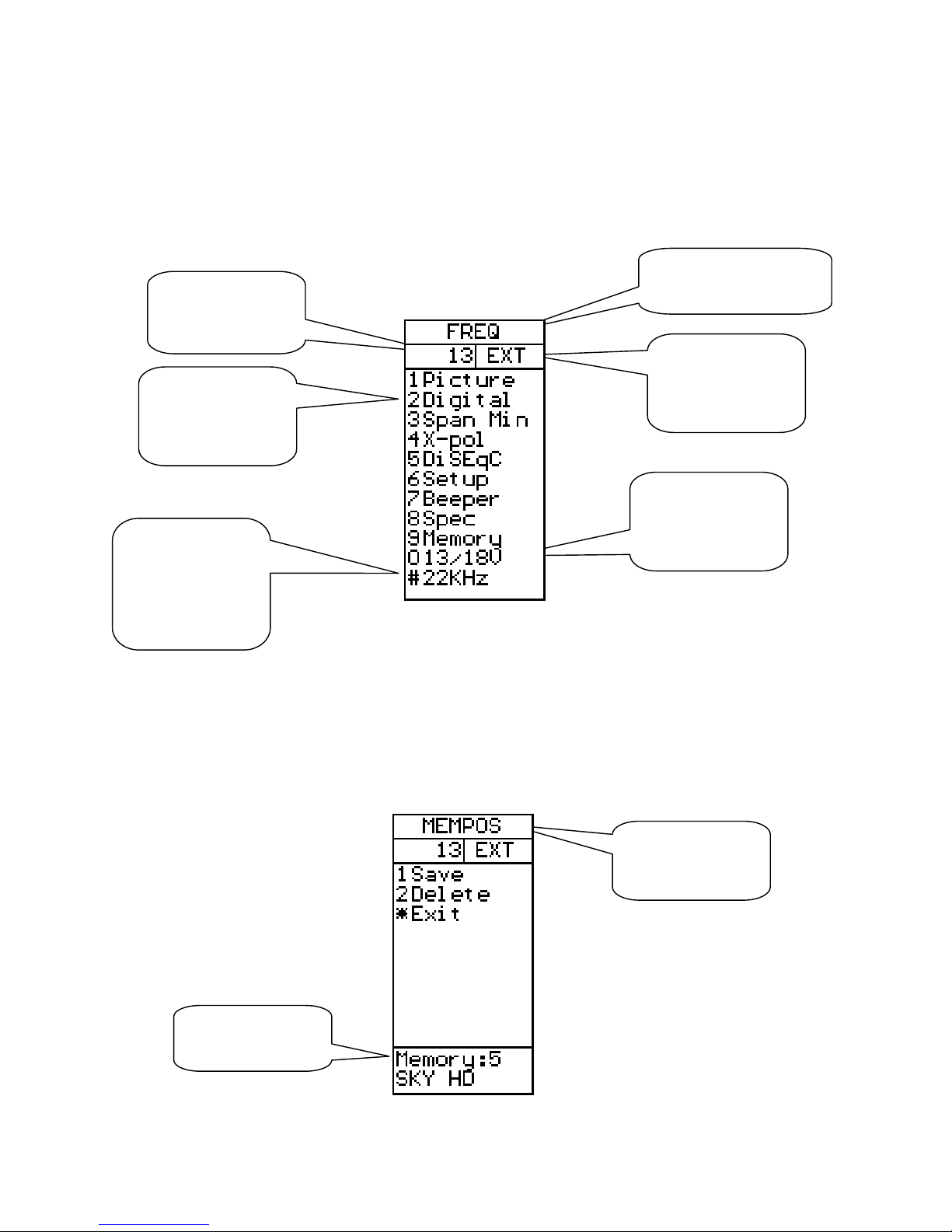
LCD
The LCD window shows the current functions available using the keypad or remote. For
each function, the keypad number is shown to the left. Also shown is the current status of
the LNB, the knob operation mode, and the battery/external power. Shown below is the
LCD display in the Spectrum mode.
When the operation can use a memory location, the lower portion of the LCD shows the
current memory selection. For this case, the knob is used to change the memory position
number that the ‘Save’ will use.
Turning the knob will
adjust frequency
Battery state or
power supply
connected
LNB power 13V
or 18V
Switch the LNB
13V/18V using
the keypad ‘0’
Switch the LNB
22kHz signal on
or off using the
keypad ‘#’
Enter Digital
Mode using the
keypad ‘2’
Memory position
and name
Turning the knob
will select the
memory location
9
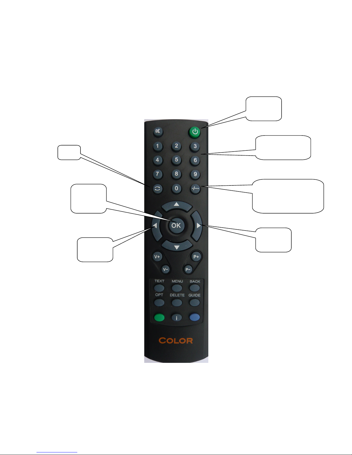
Remote Control
Power
Not used
Used same as
keypad entry
Exit
Used for keypad ‘#’
which is 22kHz
control to select band
Open TV
or Radio
channel
Previous
channel
Next
channel
10
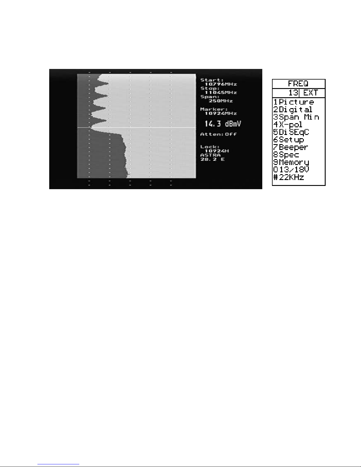
Spectrum Operation (Satellite)
The Spectrum Mode is displayed when the instrument is turned on in Satellite mode.
With a dish and LNB connected, it will show a display similar to that above. The
spectrum is displayed with the Start frequency at the top of the screen and the Stop
frequency at the bottom. The Span is the total frequency coverage or the difference
between Stop frequency and Start frequency. The current signal level (14.3 dBm in this
example) is displayed for the frequency at the Marker. The knob is used to change this to
the frequency of interest.
When Spectrum Mode is entered, the peaks are checked to see if the demodulator can
lock. If a lock occurs, the NIT data for the transponder is displayed for automatic
satellite identification. NIT data on a transponder is repeated at least every 10 seconds
and on most satellite more often than this.
The span of the Spectrum can be changed in two ways. Pressing the keypad ‘3 Span’ will
change the spectrum to the minimum span of 250MHz. For this span, each division is
1MHz. An alternate method is to use the adjustable span. Pressing the knob allows the
span to be adjusted from a minimum of 250MHz to the maximum of 1231MHz. At this
maximum span, the entire IF band from 920MHz to 2150MHz is displayed.
When span is adjusted by pressing the knob, a second press of the knob allows the “DC
Offset” of the spectrum to be adjusted for best display. A further press of the knob
restores the operation to frequency adjustment. The span setting from the knob remains
as the current setting. The “DC Offset” is restored to 0.
The current band being displayed can be changed with the 22kHz signal using the
keypad ‘# 22kHz’. For Universal LNBs, when the 22kHz is off, the band is Lo Band
(920MHz to 11900MHz) and when the 22kHz is on, the band is Hi band (11520MHz to
2150MHz) There is a small overlap from 11520MHz to 11900MHz, so a Universal LNB
can tune this range with 22kHz either on or off.

11
.
Picture)
Picture)Picture)
Picture) Allows the display of Analog or Digital channels. (see Analog Picture Mode page
16 or Digital Picture Mode page 14)
Digital)
Digital)Digital)
Digital)
Changes to Digital mode at frequency of marker.
Span Min/Max)
Span Min/Max) Span Min/Max)
Span Min/Max) Changes the spectrum bandwidth fro 250MHz to 1231MHz.
X
XX
X-
--
-Pol)
Pol) Pol)
Pol) Performs a cross polarisation check at the marker (or nearest peak) and displays
the result at the lower right of the TFT.
DiSEqC)
DiSEqC)DiSEqC)
DiSEqC)
See DiSEqC on page 18.
Setup)
Setup)Setup)
Setup) See Setup on page 19.
Beeper)
Beeper)Beeper)
Beeper) The Beeper function is enabled or disabled and can be used to provide an audio
signal of the signal level at the marker position.
Spec)
Spec)Spec)
Spec)
See the Special Spectrum functions on page 21.
Memory)
Memory)Memory)
Memory)
This allows saving or mixing the Spectrum with saved spectrum pictures. See
the Special Spectrum Mix on page 21.
13/18 )
13/18 ) 13/18 )
13/18 ) Switches the LNB voltage between 13 and 18 .
22kHz)
22kHz) 22kHz)
22kHz) Switches the LNB 22kHz signal which switches between Lo band and Hi band for
Universal LNBs.
12
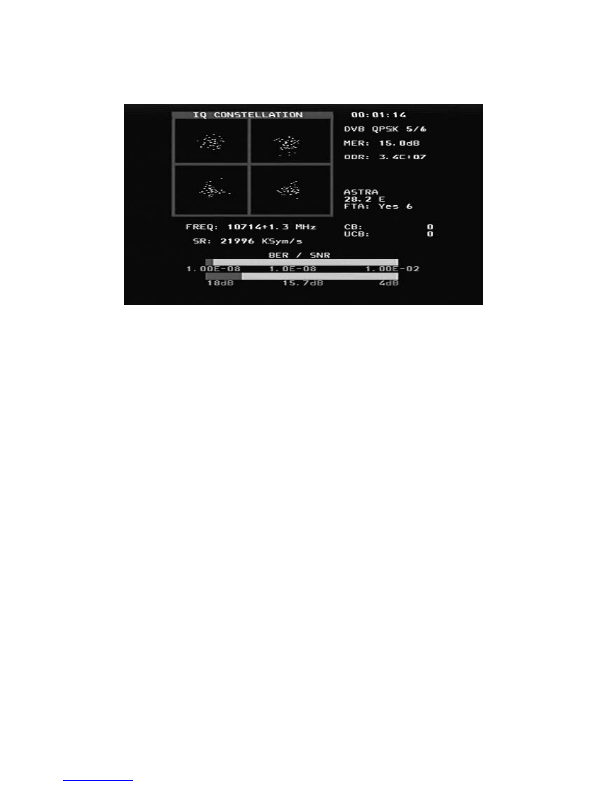
Digital Mode (Satellite)
This shows a typical constellation from a D B-S QPSK signal. The frequency and offset
are shown below the constellation diagram and the measured symbol rate is shown
below the frequency. The two thermometer bars show the BER and SNR of the signal.
The SNR thermometer increases from right to left and the BER thermometer gets smaller
from right to left, so that the best signal is shown by a longer white bar.
The lock time is shown at the top right and below this, the signal modulation and FEC.
The MER (Modulation Error Ratio) and the Output Bit Rate for the total transport stream
is also show.
When the NIT information is available, the NIT name and NIT Orbital Position appear.
Reading the SDT data shows the number of “Free to Air” channels.
A running count of the CB (Corrected Bit) and UCB (Uncorrected Block) errors is shown
as long as the signal is locked.

13
Digital Mode Functions (Satellite)
Search +/
Search +/Search +/
Search +/-
--
-)
))
) A signal search can be initiated by using the keypad ‘1 Search +’ to search
with increasing frequency or ‘2 Search –‘ with decreasing frequency. The search mode
moves to the next peak in the spectrum and attempts a lock for D B-S QPSK, D B-S2
QPSK and D B-S2 8PSK signals. The symbol rate is determined automatically. Because
the time to lock for low symbol rate signals increases the lower the symbol rate, symbol
rate signals below about 16000 will not lock during a search.
Memory)
Memory)Memory)
Memory)
Frequencies are stored in the Digital memory. (See Memory page 13)
Channels)
Channels)Channels)
Channels)
When a signal is locked, the Digital services from the SDT Service Information
will be displayed on the TFT screen.
DiS
DiSDiS
DiSEqC)
EqC) EqC)
EqC) DiSEqC commands can be initiated. (See DiSEqC page 18)
Beeper)
Beeper) Beeper)
Beeper) Enables or disables the Beeper at the frequency.
13/18 )
13/18 ) 13/18 )
13/18 ) Switches the LNB voltage between 13 and 18 .
22kHz)
22kHz) 22kHz)
22kHz) Switches the LNB 22kHz signal which switches between Lo band and Hi band for
Universal LNBs.
Exit)
Exit) Exit)
Exit) Returns to the Spectrum display.
14
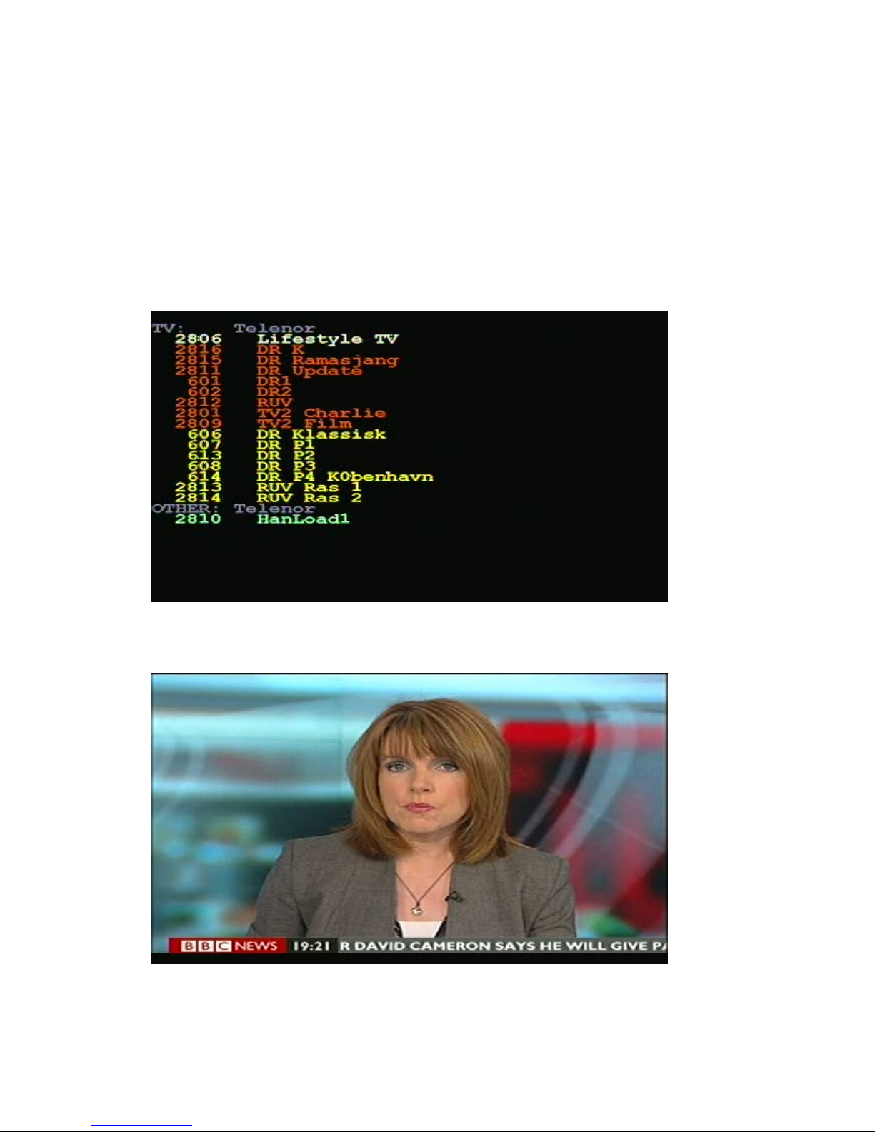
Digital Picture Mode (Satellite)
From the Digital display, when the input frequency is locked and the modulation type
displayed, the SDT data can be examined using the Channels function with keypad
‘4 Channels’. This shows a list of the services on the transponder. Encrypted channels are
shown in RED and cannot be selected. The current selected channel is shown in WHITE.
FTA channels are shown in GREEN and radio channels are shown in YELLOW.
When there are FTA channels available, the current selected channel can be opened by
keypad ‘3’.
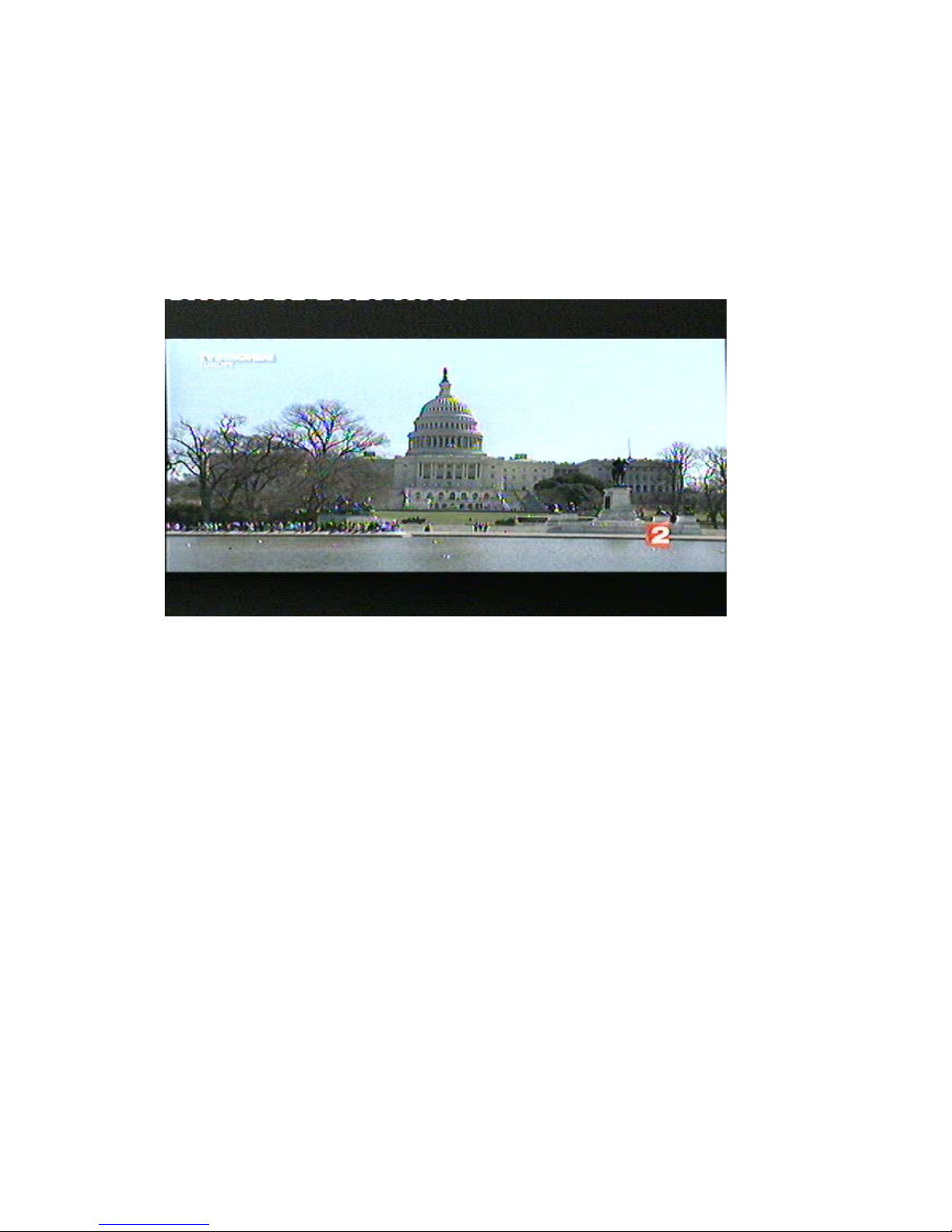
Using the keypad ‘3 Open’ shows the selected picture or if a radio channel plays the
audio.

15
Display which is available using the keypad ‘4 SNR Info’ function or the keypad ‘5 Pic Info’
functions.
16
Analog Picture Mode (Satellite)
The Analog Picture mode is selected from the Spectrum Mode by selecting ‘1 Picture’
and then ‘2 Analog’ using the keypad. The knob tunes the desired frequency which is
displayed at the bottom of the LCD and ‘0 13/18 ’ and ‘# 22kHz’ can be used from the
keypad to change polarisation and band.
This is a screenshot of T 5Monde PAL on Hotbird at 11322 .
Analog Picture Mode Functions
Invert) This switches between normal video used in the Ku band and inverted video
used in the C band. The selected position is displayed on the LCD.
Sound) This mutes or enables the sound. The audio volume and frequency are
adjusted using the small controls below the frequency knob.
Memory) This is for storing your various Analog channels. First tune in the correct
frequency to be saved. Then make sure that the memory will be saved to the correct
position shown on the LCD using the knob. Enter the Memory function with keypad
‘3 Memory’ and then use keypad ‘1 Save’. “SA E. ARE YOU SURE ?” is shown and the
confirmation is keypad ‘1 Yes’. Use the text editor to add the memory position name.
After entering the name, use keypad ‘* Save’. The frequency, 13/18 , and 22kHz
state will be saved.
.
Atten) The Attenuator of 15dB can be inserted or off. The LCD shows the attenuator
state.
13/18 ) Selection of the LNB power to 13 or 18 . The LCD shows the current
state at the top.
#. 22kHz) This sets the 22 kHz signal On or Off. The LCD shows the current state at
the top.
17
Memory Functions (Satellite)
There are four different user memory types in the Combolook Color HD instrument.
They are divided according to the type of data storage required. Each memory area is
chosen automatically depending on the type of data.
Spectrum Memory: There are 100 memory positions reserved for User data of the
spectrum waveforms. This data can be loaded and viewed or mixed with the current
signal for comparison.
Analog memory: There are 100 memory positions reserved for User data of Analog
frequencies. Each position stores the Name, frequency, 13/18 , and 22kHz state.
Digital Memory: There are 100 memory positions reserved for User data of Digital
frequencies. Each position stores the Name, frequency, 13/18 , and 22kHz state.
Digital Channel Memory: There are 100 memory positions reserved for User data of
Digital Channels. Each position stores the Name, Service ID, frequency, 13/18 , and
22kHz.
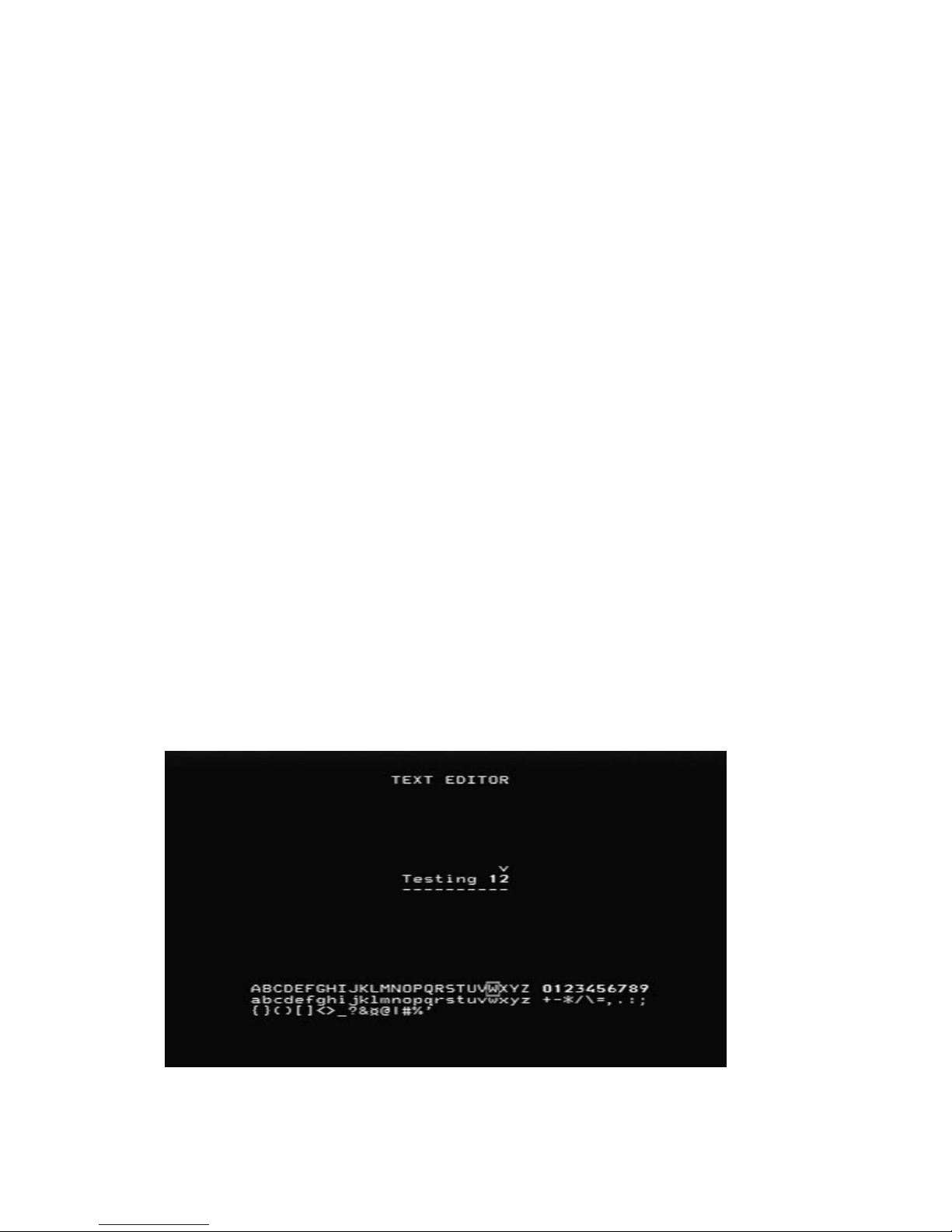
Text Editor (Satellite)
All the User memory areas use the Text Editor for saving the name for the memory
position. With the Digital Channel memory, the current channel name is entered from
the SDT data and usually this name is correct and all that is required is to save the name.
With the other memory positions, a name requires manual entry. Use the knob to select
the characters from the list and the knob select button to enter the character. Characters
can be deleted by using the keypad ‘1 Delete’ and the current position can be changed
by the keypad ‘2 Left’ or ‘3 Right’. The keypad ‘* Save’ completes the entry and saves the
name to the memory position.

18
DiSEqC Functions (Satellite)
The Combolook Color HD instrument supports all usual DiSEqC commands for the
DiSEqC specifications 1.0, 1.1 and also supports the Goto X function for easy positioner
movement. The DiSEqC commands can be accessed from several menus for
convenience.
From the Spectrum Mode: keypad ‘5 DiSEqC’
From the Digital Mode: keypad ‘5 DiSEqC’
From the Multichannel Mode: keypad ‘ 8 Spec’, keypad ‘5 MultiCH’, keypad ‘5 DiSEqC’
In the DiSEqC menu, the DiSEqC commands LNB1, LNB2, LNB3, LNB4 as well as Tone
Burst A and Tone Burst B can be sent.
For Switches, the SWx command allows the switch commands SW1 up to SW16 to be
sent.
The Motor command allows the operation of positioners. Go East and Go West move the
positioner as long as the key is pressed. Calibrate moves the positioner to the home
position, usually due south. Limits allow “soft” limits to be set or cleared for the
positioner. Position allows the setting a movement to defined positions, The Go East
command and Go West command are used to move the positioner to an optimum
position, and then that position is saved from 1 to 31. (Goto position 0 commands the
positioner to its home position.)
The Goto X (also called USALS) command removes the necessity to find positions
manually. To use the Goto X function, the instrument latitude and longitude must be
known. Once these are set, they are stored in permanent memory and so will not be lost
on power down. Once the latitude and longitude are correct, the positioner can be
commanded to move directly to a satellite orbital position.
19
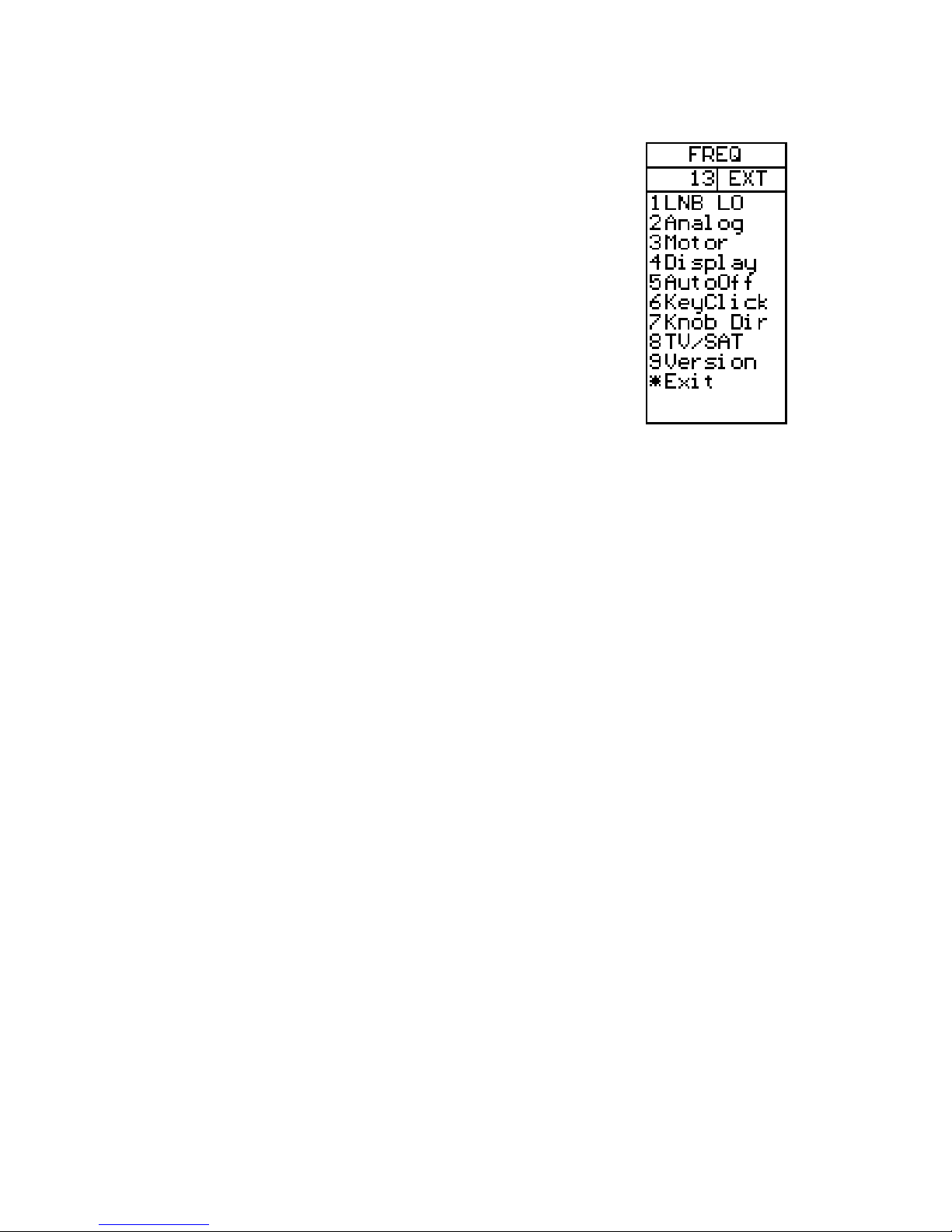
Setup (Satellite)
The Setup menu contains the functions which are used
infrequently.
LNBLO
LNBLOLNBLO
LNBLO)
) )
) The LNB type can be selected in this menu. The LNB local
oscillator down converts the satellite frequency (10670MHz to
12750MHz) to the intermediate frequency ( 920MHz to
2150MHz). If no conversion is desired, the IF setting is used.
Analog
AnalogAnalog
Analog)
) )
) The default for the Analog Picture inversion can be set
here. Normal is used by Ku Band and Invert is used for C Band.
Motor
MotorMotor
Motor)
) )
) The positioner type can be set here. The most common
positioner type is DiSEqC (Dis 1.2) and the other types supported
are Satsel and Satscan.
Display
DisplayDisplay
Display)
) )
) The display units for signal level can be set to dBu , dBm, or dBm .
The LCD contrast can be adjusted and the LCD backlight enabled or disabled. The
Spectrum Graticule can be turned on for dB guidelines.
AutoOff
AutoOffAutoOff
AutoOff)
) )
)
AutoOff can be set to turn the unit off automatically after a number of minutes
if no knob of key actions occur. AutoOff does not operate when on external power.
KeyCl
KeyClKeyCl
KeyClick
ickick
ick)
) )
)
The beep for a keypress can be enabled or disabled.
Knob Dir)
Knob Dir)Knob Dir)
Knob Dir) The direction of movement for the knob can be changed for frequency
adjustments and for other functions such as selecting the displayed picture. The default
is clockwise rotation of the knob is increasing frequency and moves the onscreen
selection down.
T /SAT)
T /SAT) T /SAT)
T /SAT) The instrument mode when turned on can be selected to start either in T mode
or Satellite mode. A third option is available which will ask the user on startup to select
the mode. If no selection is made within 20 seconds, the instrument will turn off.
ersion
ersionersion
ersion)
) )
)
The version menu displays serial number, levels of the firmware and related
information.

20
Special Functions (Satellite)
MaxHold)
MaxHold) MaxHold)
MaxHold) This sets the measurement of signal level to hold and
display the maximum received values. Once enabled, the
measurements will remain in MaxHold until expressly disabled.
Refmrkr)
Refmrkr) Refmrkr)
Refmrkr) The Reference marker allows a second marker to be
placed on the spectrum display. Adjust the marker to the required
second location and set the reference marker. Now when the
marker is moved to another location on the spectrum display, the
difference in dB level and the frequency difference are displayed.
Span Min/Max)
Span Min/Max) Span Min/Max)
Span Min/Max) The span can be changed when on this menu for
convenience. It is the same as the span setting on the Spectrum
menu.
Memory)
Memory)Memory)
Memory)
Samples of spectrum data can be saved in memory and
then either displayed or mixed with the current spectrum. When the mix function is
chosen, the current spectrum is adjusted to the same span and starting frequency, and
then the spectrum from memory is overlayed as a line image so that you can compare the
current signal with a saved spectrum.
The spectrum memory is selected using the knob and the memory position is displayed
on the TFT. Spectrum memory can be loaded for examination as well as mixed.
Table of contents


