EMIX EMBC-8025 Quick start guide

1
OPERATIONAL MANUAL
EMBC-8025
INTELLIGENT BATTERY CHARGER
Version 1.5

2
Product Overvie
EMBC-8025 is an intelligent switching mode battery charger with float maintenance. It is designed to offer
maximum life for battery. It represents the state-of-the-art of today’s technology for battery changer. The
E BC-8025 is a 2-in-1 battery charger and switching power supply with overload and short circuit
protection. The charging unit includes three stages, BULK, ABSORPTION and FLOAT intelligent battery
charger with protection against terminals reversed and shorted.
At the front panel, there is a large LCD status display of battery voltage, charging voltage, charging current,
battery connections and error message. The E BC-8025 intelligent charger is also equipped with a battery
low cut (BLC) feature that prevents the batteries from being over discharged. The build in smart cooling fan
turns when charge current reaches 1000mA. This process cools the power OSFET faster and much
quieter on standby mode.
E BC-8025 is suitable for charging batteries of up to 200Ah. Charging method is via PIC microcontroller
controlled constant current with float maintenance. ulti level protections are incorporated to prevent
premature batteries failure, such as battery low cut, battery over voltage charging, over current and
polarity reversed charging.

3
Features
•Intelligent PIC microcontroller controlled 24V battery charger
•Constant current charging with Float maintenance
•Battery over charge protection (exceed batteries limits)
•Battery charge terminals reversed protection (cause serious damage to batteries and equipment)
•Input over voltage protection (48V Batt. Connected to charger may damage internal circuitry)
•Input low voltage protection (12V Batt. Connected to charger cause serious over charging)
•Charge 24V batteries up to 10 to 200Ah (fully charge 24V/80Ah batteries within 24Hrs)
•Backup battery low auto disconnect and trigger buzzer sound alert
•240VAC main power failed and resumed monitoring
•Liquid crystal display (LCD) voltage, Ampere, battery conditions and error message
•Voltage Output with 24VDC (4A) utility power supply unit
•Output short circuit and overload protections
•Real main switch and fused AC input socket to avoid accidentally switching off system
4
Front Vie and Rear Vie
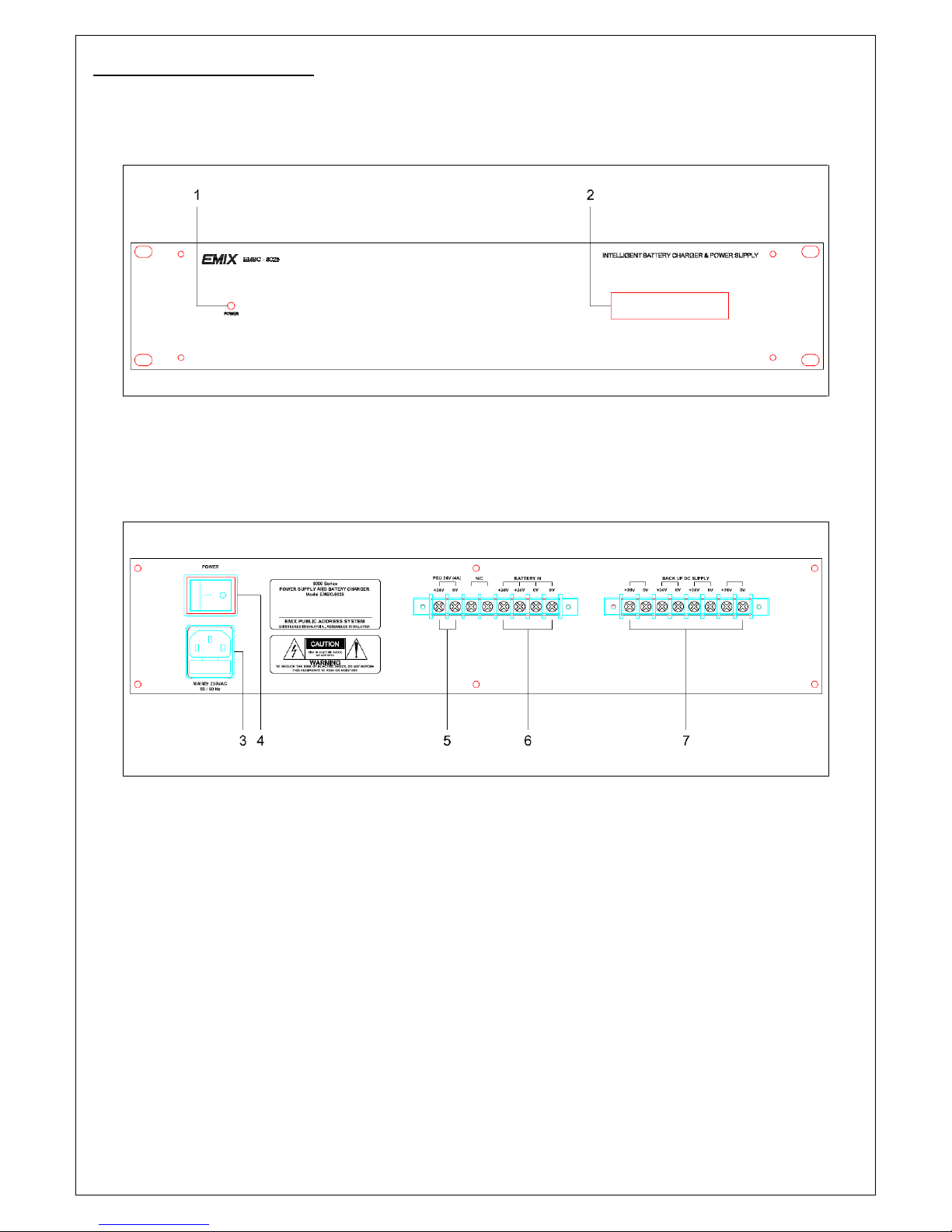
Figure 3.1 Front view of Battery Charger
Figure 3.2: Rear view of the Battery Charger

5
Front Panel and Rear Panel Indication
EMBC-8025 Intelligent Battery Charger ith Po er Supply
3.1.0 Front Panel Indicator
1 Mains LED – The power LED is red if the battery charger is connected to the main and switch on
2 LCD Display – Shows the battery voltage, charge current, charge voltage to the battery and error
message.
3.2.0 Rear Panel connection
3 Mains po er Inlet – A socket for connecting the battery charger to the mains power. ain voltage
of 240V ± 10%
4 ON/OFF S itch – Connects and disconnects the main power supply.
5 Po er Supply Unit (24VDC) – To equipments DC supply for total load maximum of 4A.
6 Battery in – Power Connector to the Batteries (Can be charged up to 200AH)
7 Backup Po er Supply (24VDC) – Power out connector to the 24VDC (>20A) limit output back-up
power on each contact for the E IX rack systems products.
** NOTE: It is very important to determine the size of cable for back up supplies. (Ex: Size of the cable from
Battery Charger to Battery and Battery Charger connect to others equipments).
** NOTE: Always Double Check on the positive (+) & Negative (-) priority before connecting to the unit

6
Schematic Diagram / Connection diagram
I PORTANT:
The Batteries must
be connected to the
Battery Charger’s
OUTPUT

7
Operation:-
Bul charge (Constant Current Charge)
Primary constant current charging where approximately 80% of the charging happens. The charger delivers
maximum voltage until the terminal voltage has risen to the preset level. After a number of hours, the
charger goes on to the next phase of charging (absorption).
Absorption (Constant Voltage Charge)
Final charging to almost 100%, voltage is kept at the preset level. During this case, the current is gradually
reduced. When the preset length of time is reached and charging current drops to the preset level, the
charger automatically switches to float charge mode.
Float charge
The charging process range between 95% and 100%. The battery receives a pulse if the voltage falls. This
stage will keep the battery in a good condition if it is not being used.
Equalization
BATTERIES ARE DANGEROUS
The E BC-8025 is design to charge 24V SLA (Sealed Lead-Acid) battery of 10A to 200A (over 4KW of DC
power). It is of UT OST importance that you follow the instructions each time you use the charger.
** NOTE: ost of the battery would drained significantly over night
** NOTE: E BC-8025 must be connected to the batteries with minimum voltage of 16V for normal
operation.
8
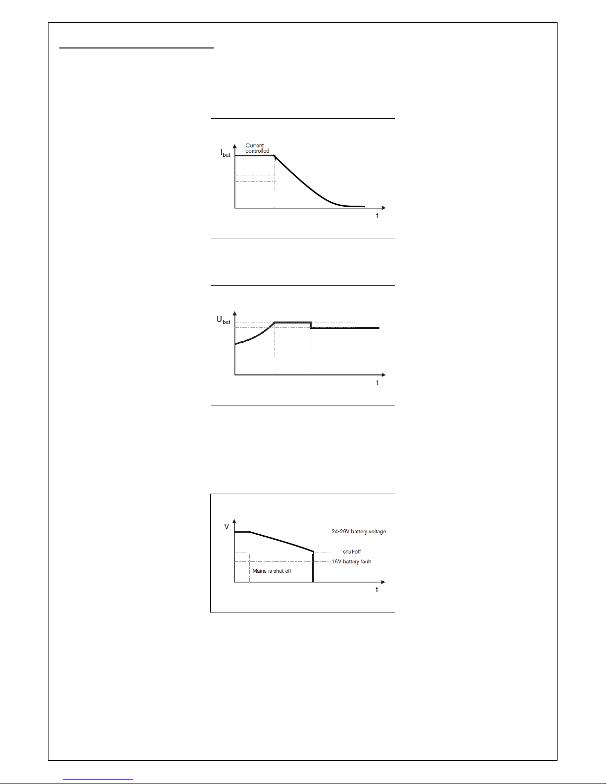
Charge voltage and current:-
When the unit is connected to the battery (battery series), the charge current and charge voltage are as
shown in figure 4.1 and figure 4.2 respectively.
Figure 4.1: Charge current
Figure 4.2: Charge voltage
When the main voltage is removed, the output voltage on the main 24V output is shown in figure 4.3
Figure 4.3: Output voltage (mains voltage removed)
Bulk Absorption Float
18V
V
Bulk Absorption Float

9
Operation:-
When switching from the mains to the backup power:
•The main system output will decrease in voltage from the charge voltage to the battery voltage (the
system will not be affected by this).
•The auxiliary outputs can have a small dip in voltage, depending on the load (if the load is very high, the
system may report this as a fault (blinking or blank-out) on the LCD Display).
A battery voltage below 18V will automatically disconnect the load from the battery (this is for deep
discharge protection). When the mains voltage is restored, the unit will reset and start to charge the
battery to be ready for the next power failure.
** NOTE: If E BC-8025 Battery charger couldn’t detect any battery, kindly check the battery manually by
using ulti-meter or contact us through our website. Battery’s minimum voltage must be 16V.
10
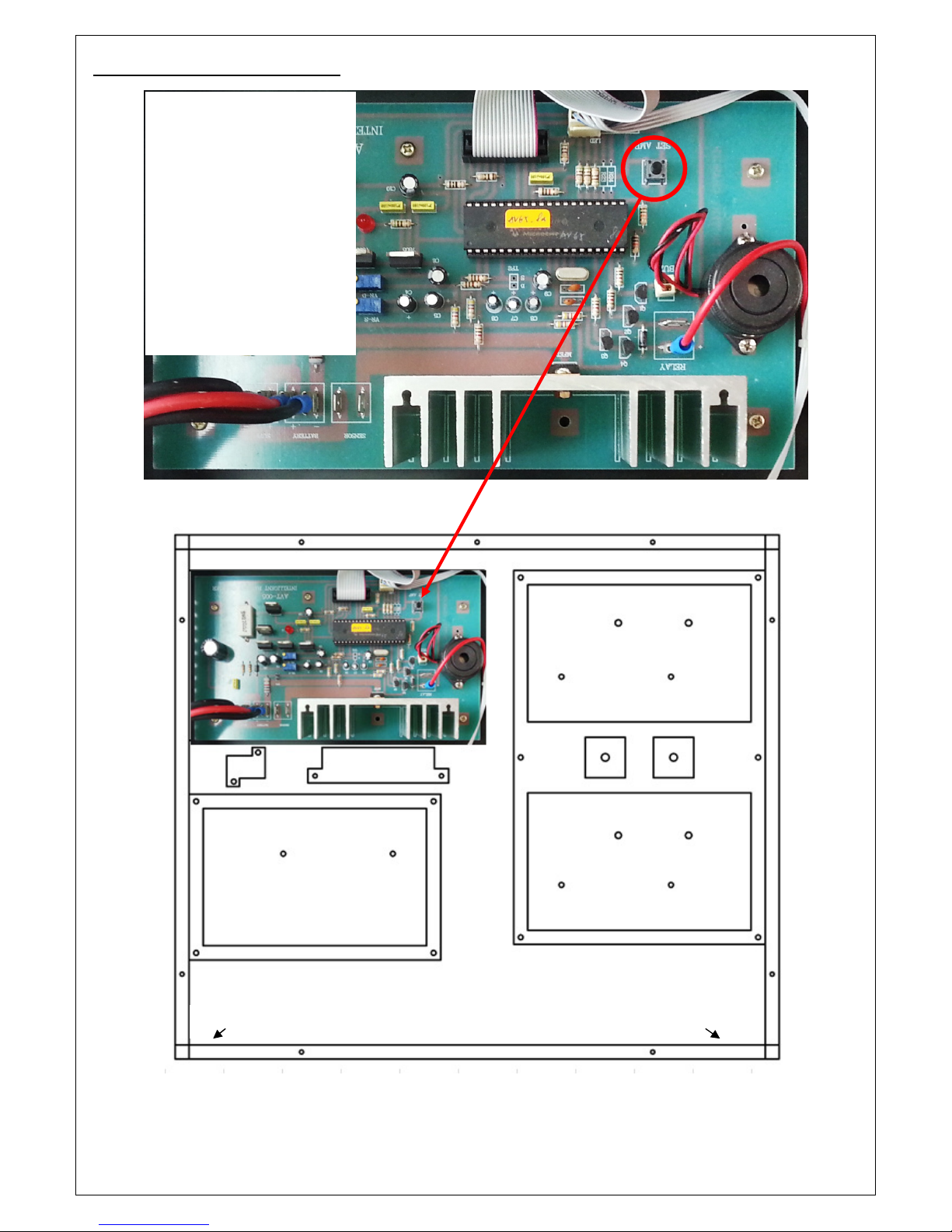
Setting on Current Charging:-
ain Control Board
E BC-8025 Internal Structure
Step 1
: Press & Hold the
button for 3Sec to enter
into the charging current
setting menu
Step 2: Select the Current
charging (1A to 5A) by
pressing the button
Step 3: Press & Hold the
button for 3sec to escape
the charging current menu
Power Supply Unit
Power Supply Unit
Power Supply Unit
Fan
Front Panel
LCD
LED
Rear Panel

11
Technical Specifications
Input voltage 240V AC ± 10%
Charging voltage 27V to 29V DC
inimum Charging Voltage 16V
Bulk Constant current (PIC microcontroller controlled)
Absorption 29V DC (Preset limit)
Float 27V DC (Preset limit)
Charging current 1 to 5A (PIC microcontroller controlled); Default is 3A
ax Power consumption 200W
Protections Over current, over voltage, over heating, short circuit, Low battery Indicator
LCD status displays Battery volt, charge volt, charge current, battery conditions
Indicators LED AC main failure, switching power supply status
Cooling Smart FAN cooling system with charge, low cut at 18V
Terminals Battery input, 24V (4A) output, battery backup/low cut outputs
Battery backup Battery output 20A x 4 with low cut and fused protection (max. 80A)
Utility power supply 24V DC 4A switching power supply with changeover relay
AC Fuse 3A
DC Backup Fuse 30A x 4nos (At Every DC Backup output)
Battery Input 24VDC Fuse Polarity Positive 20A; Polarity Negative 20A
Utility Power Supply Fuse 5A
Input Connection Screw Terminal (Connect to battery)
Output Connection Screw Terminal (Connect to System)
Dimension (W x H x D) 482 x 88 x 390mm
Gross Weight 9.3kg
Net Weight 7.3kg

12
Dimension:-

13
Parts Included:-
Quantity Component
1 E BC-8025 24VDC Battery Charger with Power Supply Unit
1 Operation Instruction anual
1 ains Plug

14
Only E IX Technical Service Centers are allowed to make warranty repairs. Send the equipment directly to
AV Electronics arketing Sdn Bhd, or contact us for a list of Emix Technical Centers. This warranty is not
valid if repairs are performed by unauthorized personnel or service centers.
This warranty covers only repairs and replacement of defective parts. Costs and risk of transportation as
well as removal and installation of the product/equipment from the main system are to be borne by the
purchaser. This warranty shall not extend to the replacement of the unit.
This warranty does not cover damages caused by misuse, neglect, accident of the products as well as using
the product with power supply voltage other than shown on the product, or any other power supply
source / adaptor not recommended by the manufacturer. This warranty does not cover damages caused by
fire, earthquakes, floods, lightning and every cause not directly related to the unit.
This warranty does not include any indemnity in favor of the purchaser or the dealer for the period of use
of the unit; moreover the warranty does not cover any damages which may be caused to people and things
when using the products.
This warranty certificate is valid only for the described product, and is valid for a period of 12 months from
the date of purchase or for a longer period in countries where this is stated by a national law. In this case,
the extension is valid only in the country where the product is purchased.
AV ELECTRONICS ARKETING SDN BHD is not obliged to modify previously manufactured products under
warranty if the design changes or improvements are made.
Information contained in this manual is subject to change without prior notice and does not represent a
commitment on the part of the vendor. AV ELECTRONICS ARKETING SDN BHD shall not be liable for any
loss or damages whatsoever arising from the use of information or any error contained in this manual.
It is recommended that all services and repairs on this product be carried out by AV Electronics arketing
Sdn Bhd or its authorized service centers/agents.
E IX products must only be used for the purpose they were intended by the manufacturer and in
conjunction with this operating manual.
AV ELECTRONICS ARKETING SDN BHD cannot accept any liability whatsoever for any loss or damages
caused by service, maintenance or repair by unauthorized personnel, or by use other than that intended by
the manufacturer.

15
NOTES:
Intentionally left blank

16
Professional Public Address System
www.emix.com.my
Table of contents


