emmeti Tank in Tank Series Guide

MANUALE INSTALLAZIONE ED USO
IT
INSTALLATION AND USE MANUAL
GB
ANWEISUNGEN FÜR MONTAGE UND INSTANDSETZUNG
DE
FR MANUEL D’INSTALLATION ET D’UTILISATION
Tank in Tank

INDEX
DEDE
página 9
Wir danken Ihnen für das Vertrauen, das Sie unserem Unternehmen durch den
Kauf eines Boiler
Bitte lesen Sie das vorliegende Handbuch vor der ersten Inbetriebnahme des
Gerätes aufmerksam durch und bewahren Sie dieses in dessen unmittelbarer
Nähe auf Boiler.
Die in dieser Veröffentlic
hung enthaltenen Daten können aus technischen
und/oder kommerziellen Anforderungen ohne Voranzeige in jedem beliebigen
Momemt abgeändert werden.
Wichtig!
Die Handbücher an einen trockenem Ort aufbewahren, damit sie min-
destens weitere 10 Jahre für eventuelle Informationen vorhanden sind.
FRFR
page 12
Nous vous remercions de la confiance que vous nous avez accordée en
acquérant le Bouilleur.
Nous vous invitons à lire attentivement ce manuel dans lequel figurent
toutes les caractéristiques techniques et toutes les informations néces-
saires pour le bon fonctionnement du Bouilleur.
Les données contenues dans le manuel peuvent faire l’objet de modifica-
tions jugées nécessaires en vue de l’amélioration du produit.
Attention !
Veiller à conserver les manuels à l’abri de l’humidité pour prévenir leur
détérioration et de telle sorte qu’ils puissent être consultés à tout momen
ITIT
pagina 3
Vi ringraziamo per la fiducia concessaci nell’acquisto del Bollitore.
Vi invitiamo a leggere attentamente questo manuale dove sono riportate le
caratteristiche tecniche e tutte le informazioni utili per ottenere un corretto
funzionamento del Bollitore.
I dati possono subire modifiche ritenute necessarie per il miglioramento
del prodotto.
Attenzione!
Conservare i manuali in luogo asciutto per evitare il deterioramento, per
eventuali riferimenti futuri.
GBGB
page 6
Thank you for your choice of the Tanks.
Carefully read this manual which contains the specifications and all useful
information for correct operation of the Tanks.
Further improvements on product, may introduce, without prior notice,
changes of contents herein.
Warning!
Keep these manuals in a dry place avoiding in this way to spoil them.
1 Descrizione Bollitore ................... 3
2 Indicazioni per l’installazione ....... 5
1 Description Tanks ....................... 6
2 Installation Istructions................ 8
1 Beschreibung Speicher ................. 9
2 Aufstellungsanweisungen ............ 11
1 Description Bouilleur ................... 12
2 Instructions pour l’installation .... 14
Installazione serpentini rimovibili - Removable exchanger installation
Abnehmbare warmetauscher - Montage serpentin extractible ......................15
Dati tecnici in conformità al Regolamento - Technical data in accordance
with European regulation - Technische Daten in Über einstimmungmit der EU
Verordnung - Donné es techniques conformément au règulment ...........................16
ITIT
GBGB
DEDE
FRFR

3
1. TITOLO ITIT
1. DESCRIZIONE BOLLITORE
Tank in Tank bollitore combinato con 1 serpentino fisso
Tank in Tank bollitore combinato con 2 serpentini fissi
H
A
B
C
D
E
F
O
RS NMS MLI
Q
P
R
1” IS
290
G
1” US
1/2” Sonda 1” 1/4 Anodo
1” Ricircolo
H
A
B
C
D
E
F
RS NMS
RSS
L
M
Q
P
R
1” IS
MSS
I
290
G
1” US
1/2” Sonda 1” 1/4 Anodo
1” Ricircolo

4
1. TITOLO ITIT
1. DESCRIZIONE BOLLITORE
- Vetrificazione parte sanitaria, non trattato il serbatoio
- Isolamento in poliestere flessibile spessore 100 mm
- Rivestimento isolamento in SKY in PVC colore grigio
- Conforme art. 4.3 direttiva PED 2014/68/UE
- Conforme DIN 4753.3 e UNI 10025
Dati tecnici
- Pressione massima di esercizio serbatoio: 4 bar
- Pressione massima di esercizio sanitario: 6 bar
- Pressione massima di esercizio serpentini: 10 bar
- Temperatura massima di esercizio: 95 °C
- Pressione di prova: 6 bar (serbatoio), 9 bar sanitario, 15 bar (serpentini)
Nota: nel circuito sanitario in prossimità del bollitore deve essere installata una valvola di sicurezza con taratura massima = 6 bar e vaso d’espansione
adeguato alla volumetria dell’impianto sanitario.
Modello u.m. 600 1000
Capacità totale (Volume utile) ℓ640 (470/170) 830 (610/220)
Mandata riscaldamento 1”½ A mm 1450 1695
Libero 1”½ B mm 1160 1190
Libero 1”½ C mm 950 1050
Libero 1”½ D mm 890 910
Ritorno riscaldamento 1”½ E mm 590 640
Ritorno caldaia 1”½ F mm 594 844
Sfiato 1/2” G mm In Alto
Sonda riscaldamento 1/2” I mm 1450 1745
Sonda riscaldamento 1/2” L mm 1235 1440
Sonda riscaldamento 1/2” M mm 1055 1290
Mandata serpentino superiore (*) 1” MSS mm 1370 1635
Ritorno serpentino superiore (*) 1” RSS mm 980 1170
Mandata solare 1” MS mm 880 880
Ritorno solare 1” RS mm 330 330
Sonda riscaldamento solare 1/2” N mm 595 595
Scarico 3/4” 0 mm 240 240
Interasse R mm 240 240
Acqua fredda sanitario 1” IS mm - -
Acqua calda sanitario 1” US mm - -
Altezza H mm 1710 1985
Ø con isolamento P mm 750 790
Ø senza isolamento Q mm 950 990
Superficie di scambio serpentino superiore (*) m21,5 2,0
Superficie di scambio serpentino inferiore m22,5 3,0
Contenuto serpentino superiore ℓ8,0 11,8
Contenuto serpentino inferiore ℓ14,4 16,7
Peso modelli 1 serpentino (a vuoto) kg 184 215
Peso modelli 2 serpentini (a vuoto) kg 205 240
Dispersione S (**) W 126 138
Dispersione Specifica W/K 2,80 3,07
Classe energetica - -
(*) Solo su modelli con due serpentini fissi - (**) In conformità a UNI EN 12897 con Tacqua = 65 °C e Tambiente = 20 °C
Tank in Tank bollitore combinato con 1 o 2 serpentini fissi

5
ITIT
6. Come è noto il contatto tra metalli diversi può dar luogo a fenomeni
di corrosione.
In tal senso si consiglia di interporre un opportuno giunto dielettrico
tra gli attacchi posti nel bollitore e le corrispondenti tubazioni.
7. La conducibilità elettrica dell’acqua non deve essere inferiore a 150
μS/cm o superiore a 1000 μS/cm.
2. INDICAZIONI PER L’INSTALLAZIONE
Quanto di seguito riportato è determinante per la validità della
garanzia.
1. L’installazione deve:
– Essere eseguita da un installatore qualificato.
– Prevedere, dove necessario, un riduttore di pressione per l’acqua in
ingresso.
– Prevedere una valvola di sicurezza tarata secondo quanto riportato
nell’etichetta dati tecnici applicata sul boiler.
– Prevedere un vaso espansione (vedi tabella dimensionamento vaso
d’espansione) commisurato alle dimensioni del boiler (si consiglia di
far eseguire il calcolo ad un termotecnico).
2. Prima della messa in funzione è bene verificare il serraggio delle viti
della flangia (applicare coppia pari a 20 Nm).
3. La temperatura del contenuto del boiler deve sempre essere inferiore
a 95 °C.
4. Il riempimento deve essere iniziato dal lato sanitario onde evitare una
possibile implosione del bolllitore sanitario.
5. Il bollitore è dotato di un anodo al magnesio. Per evitare fenomeni di
corrosione controllare l’anodo ogni 12 mesi (6 mesi in caso di acque
particolarmente aggressive) e sostituirlo se consumato o pulirlo se
ricoperto di calcare.
Dimensionamento vaso d’espansione
Valori in litri relativi a:
- pressione di precarica pari a 2,5 bar
- pressione taratura valvola di sicurezza pari a 6,0 bar
- espansione da 10 a 90 °C.
Negli impianti con anelli di ricircolo sanitari, si deve considerare anche il volume d’acqua presente nelle tubazioni.
Modello bollitore
Volume vaso
d’espansione (I)
600 N, 600 N 1S 1000 N, 1000 N 1S
Riscaldamento Sanitario Riscaldamento Sanitario
40°C 7,0 2,6 9,2 3,3
50°C 11,1 4,0 14,4 5,2
60°C 15,8 5,7 20,5 7,4
70°C 21,2 7,7 27,5 9,9
80°C 27,1 9,8 35,2 12,7
90°C 33,6 12,2 43,6 15,7
Temperatura di accumulo

6
GBGB
1. DESCRIPTION TANKS
Tank in Tank kettle combined with 1 fixed coil
Tank in Tank kettle combined with 2 fixed coils
H
A
B
C
D
E
F
O
RS NMS MLI
Q
P
R
1” IS
290
G
1” US
1/2” Probe 1” 1/4 Anode
1” Recirculation
H
A
B
C
D
E
F
RS NMS
RSS
L
M
Q
P
R
1” IS
MSS
I
290
G
1” US
1/2” Probe 1” 1/4 Anode
1” Recirculation

7
1. DESCRIPTION TANKS GBGB
- Vetrification health care, not treated the tank
- 100 mm thick flexible polyester insulation
- Insulation coating SKY Grey PVC.
- In compliance with directive 2014/68/EU, art. 4.3.
- Conform DIN 4753.3 and UNI 10025
Technical data
- Maximum tank operating pressure: 4 bar
- Maximum working pressure: 6 bar
- Maximum working pressure of coils: 10 bar
- Maximum working temperature: 95 ° C
- Test pressure: 6 bar (tank), 9 sanitary bar, 15 bar (serpentine)
Note: in the sanitary circuit near of the boiler must be installed a safety valve with calibration maximum = 6 bar and the expansion vessel adapted to the
volume of the sanitary system.
Model u.m. 600 1000
Total capacity (useful volume) ℓ640 (470/170) 830 (610/220)
Heating supply 1”½ A mm 1450 1695
Free 1”½ B mm 1160 1190
Free 1”½ C mm 950 1050
Free 1”½ D mm 890 910
Heating return 1”½ E mm 590 640
Boiler return 1”½ F mm 594 844
Venting 1/2” G mm I tall
Heating probe 1/2” I mm 1450 1745
Heating probe 1/2” L mm 1235 1440
Heating probe 1/2” M mm 1055 1290
Upper serpentine delivery (*) 1” MSS mm 1370 1635
Upper serpentine return (*) 1” RSS mm 980 1170
Solar supply 1” MS mm 880 880
Solar return 1” RS mm 330 330
Solar heating sensor 1/2” N mm 595 595
Exhaust 3/4” 0 mm 240 240
Wheelbase R mm 240 240
Sanitary cold water 1” IS mm - -
Sanitary hot water 1” US mm - -
Height H mm 1710 1985
Ø with insulation P mm 750 790
Ø without insulation Q mm 950 990
Upper serpentine exchange surface (*) m21,5 2,0
Lower serpentine exchange surface m22,5 3,0
Upper serpentine content ℓ8,0 11,8
Lower serpentine content ℓ14,4 16,7
Weight models 1 serpentine (vacuum) kg 184 215
Weight models 2 coils (vacuum) kg 205 240
Dispersion S (**) W 126 138
Specific Dispersion W/K 2,80 3,07
Energetic class - -
(*) Only on models with two fixed coils - (**) In compliance with UNI EN 12897 with Twater = 65 °C e T environment= 20 °C
Tank in Tank kettle combined with 1 or 2 fixed coils

8
GBGB
2. INSTALLATION ISTRUCTIONS
6. As it is known the contact between different metals can give rise to
corrosion phenomena.
In this sense, it is advisable to place a suitable dielectric joint
between the connections in the storage tank and the corresponding
pipes.
7. The electrical conductivity of the water must not be less than 150 μS /
cm or more than 1000 μS / cm.
The following is decisive for the validity of the guarantee.
1. The installation must:
- Be performed by a qualified installer.
- Provide, where necessary, a pressure reducer for incoming water.
- Provide a safety valve calibrated according to what is reported on the
technical data label applied on the boiler.
- Provide an expansion vessel (see expansion vessel dimensioning table)
commensurate with the dimensions of the boiler (it is advisable to
have the calculation performed by a thermo technician).
2. Before tightening up, it is advisable to check the tightness of the
screws of the flange (apply torque equal to 20 Nm).
3. The temperature of the contents of the boiler must always be below
95 ° C.
4. The filling must be initiated from the sanitary side in order to avoid a
possible implosion of the sanitary cylinder.
5. The kettle is equipped with a magnesium anode. To avoid corrosion,
check the anode every 12 months (6 months in case of particularly
aggressive water) and replace it if worn or if it is covered with lime-
stone.
Expansion kettle sizing
Values in liters relative to:
- preload pressure equal to 2.5 bar
- safety valve calibration pressure equal to 6.0 bar
- expansion from 10 to 90 ° C.
In systems with sanitary recirculation rings, the volume of water present in the piping must also be considered.
Model tank
Expansion tank
volume (I)
600 N, 600 N 1S 1000 N, 1000 N 1S
Heating Heating Heating Heating
40°C 7,0 2,6 9,2 3,3
50°C 11,1 4,0 14,4 5,2
60°C 15,8 5,7 20,5 7,4
70°C 21,2 7,7 27,5 9,9
80°C 27,1 9,8 35,2 12,7
90°C 33,6 12,2 43,6 15,7
Storage temperature

9
1. TITOLO ITIT
1. BESCHREIBUNG SPEICHER DEDE
Tank in Tank Wasserkocher kombiniert mit einer festen Spule
Tank in Tank Wasserkocher kombiniert mit 2 festen Spulen
H
A
B
C
D
E
F
O
RS NMS MLI
Q
P
R
1” IS
290
G
1” US
1/2” Sonde 1” 1/4 Anode
1” Rezirkulation
H
A
B
C
D
E
F
RS NMS
RSS
L
M
Q
P
R
1” IS
MSS
I
290
G
1” US
1/2” Sonde 1” 1/4 Anode
1” Rezirkulation

10
ITIT
DEDE
1. BESCHREIBUNG SPEICHER
- Vetrification Gesundheitsfürsorge, nicht der Tank behandelt
- 100 mm dicke, flexible Polyesterisolierung
- Isolations-Beschichtung SKY PVC grau.
- Gemäß Richtlinie Nr. 2014/68/EU (Art. 4, Abs. 3).
- Conforme DIN 4753.3 e UNI 10025
Technisches Datenblatt
- Maximaler Tankbetriebsdruck: 4 bar
- Maximaler Arbeitsdruck: 6 bar
- Maximaler Arbeitsdruck der Windungen: 10 bar
- Maximale Arbeitstemperatur: 95 ° C
- Prüfdruck: 6 bar (Tank), 9 Sanitärriegel, 15 bar (Serpentin)
Hinweis: Im Sanitärkreislauf in der Nähe des Warmwasserbereiters muss ein Sicherheitsventil mit einer maximalen Einstellung = 6 bar und ein Ausdeh-
nungsgefäß installiert werden, das für das Volumen der Brauchwassersystem geeignet ist.
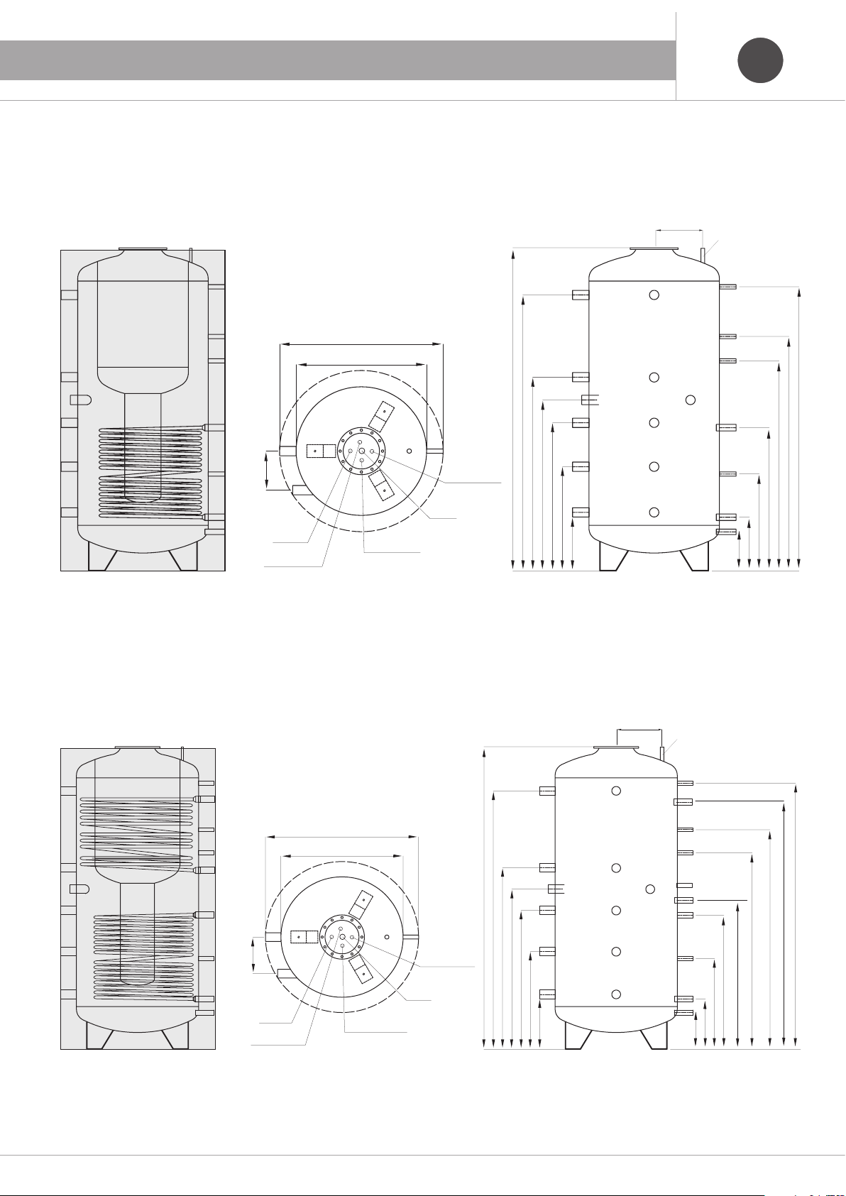
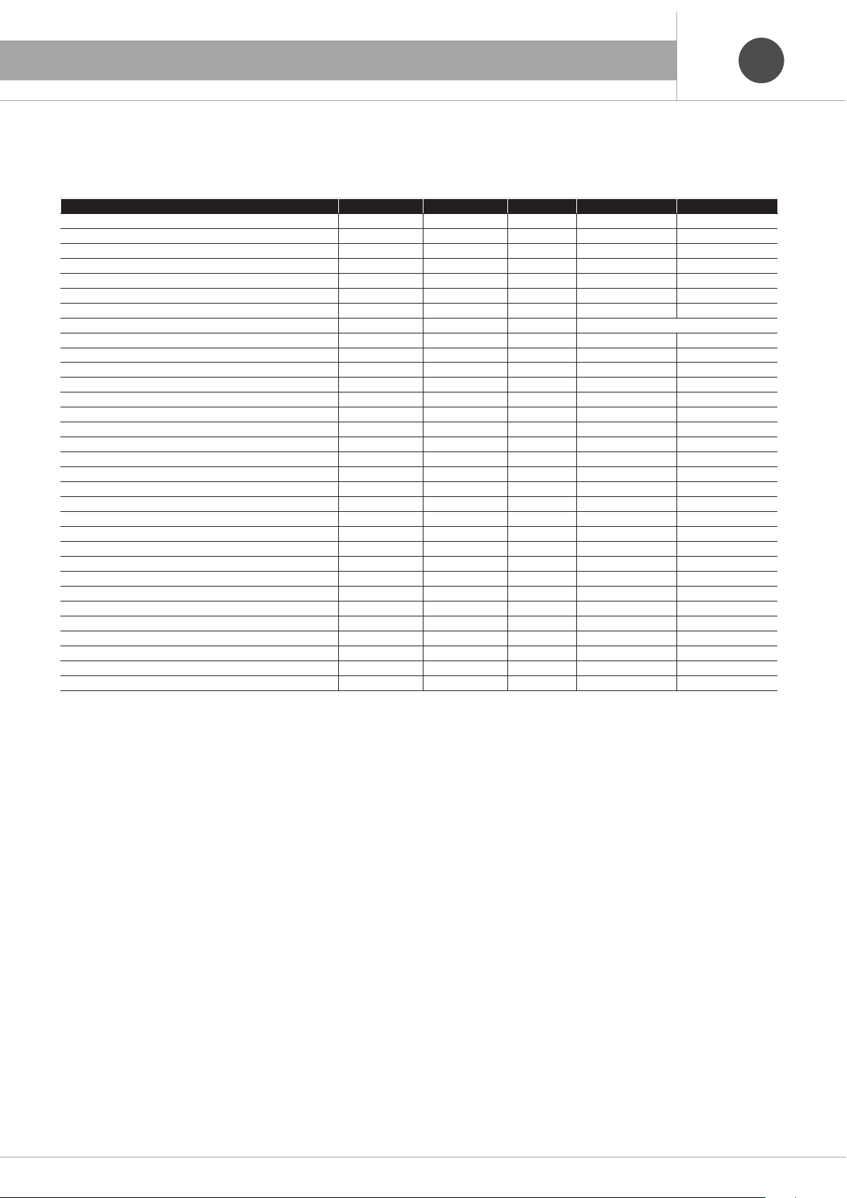
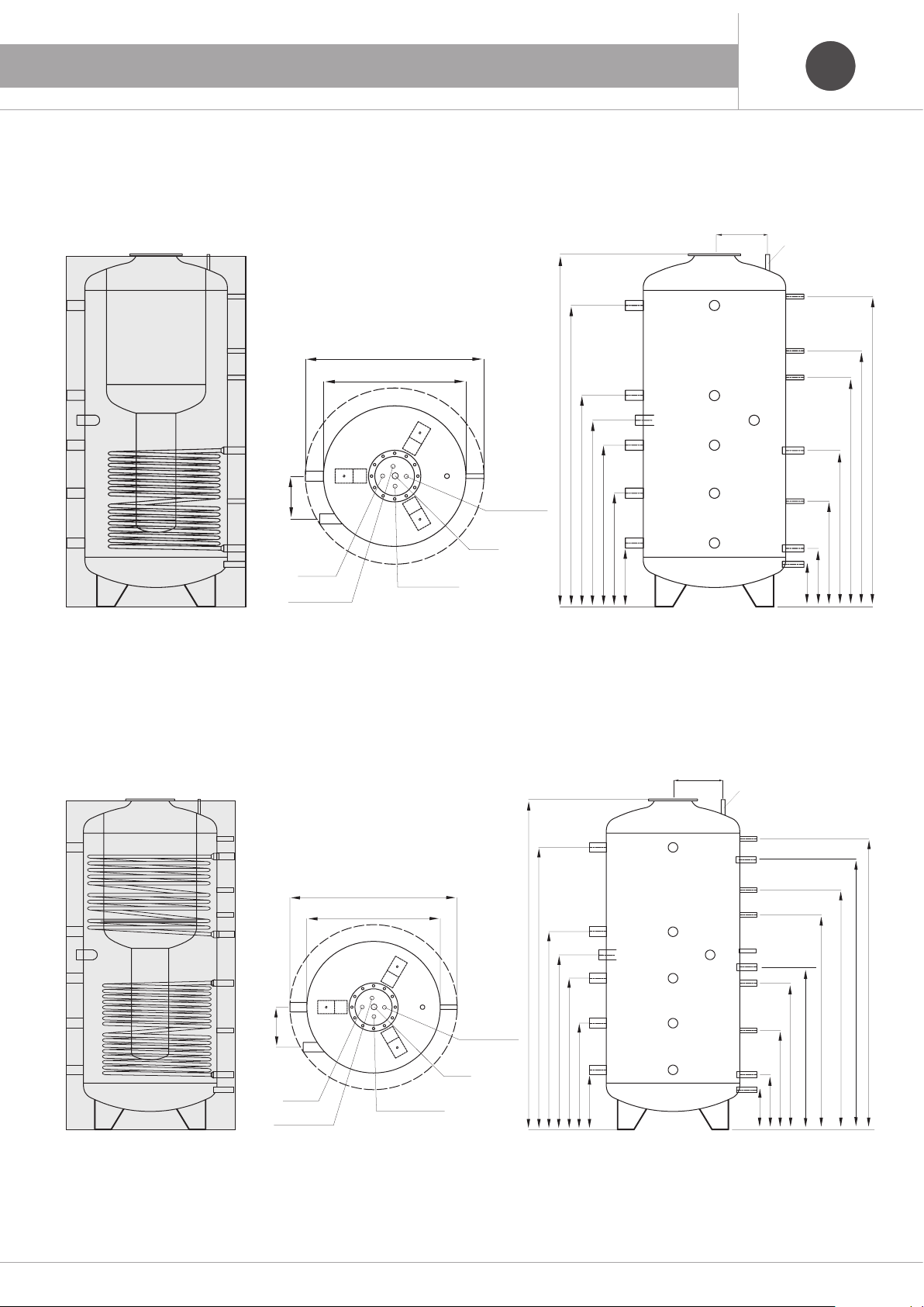
Modell u.m. 600 1000
Gesamtkapazität (Nutzvolumen) ℓ640 (470/170) 830 (610/220)
Wärmeversorgung 1”½ A mm 1450 1695
kostenlos 1”½ B mm 1160 1190
kostenlos 1”½ C mm 950 1050
kostenlos 1”½ D mm 890 910
Heizungsrücklauf 1”½ E mm 590 640
Kesselrücklauf 1”½ F mm 594 844
Venting 1/2” G mm Hoch
Heizsonde 1/2” I mm 1450 1745
Heizsonde 1/2” L mm 1235 1440
Heizsonde 1/2” M mm 1055 1290
Obere Serpentinenabgabe (*) 1” MSS mm 1370 1635
Obere Serpentinenrückkehr (*) 1” RSS mm 980 1170
Solarversorgung 1” MS mm 880 880
Solar Rückkehr 1” RS mm 330 330
Solar Sensor gestiegen 1/2” N mm 595 595
Auspuff 3/4” 0 mm 240 240
Radstand R mm 240 240
Sanitäres kaltes Wasser 1” IS mm - -
Sanitär heißes Wasser 1” US mm - -
Höhe H mm 1710 1985
Ø mit Isolierung P mm 750 790
Ø ohne Isolierung Q mm 950 990
Obere Serpentinenaustauschfläche (*) m21,5 2,0
Untere Serpentinenaustauschfläche m22,5 3,0
Oberer Serpentinengehalt ℓ8,0 11,8
Geringerer Serpentingehalt ℓ14,4 16,7
Gewichtsmodelle 1 Serpentin (Vakuum) kg 184 215
Gewichtsmodelle 2 Spulen (Vakuum) kg 205 240
Dispersion S (**) W 126 138
Spezifische Dispersion W/K 2,80 3,07
Energieklasse - -
(*) Nur bei Modellen mit zwei Festspulen - (**) In Übereinstimmung mit UNI EN 12897 mit Twater = 65 °C e T Umwelt = 20 °C
Tank in tank Wasserkocher kombiniert mit 1 oder 2 festen Spulen

11
1. TITOLO ITIT
DEDE
2. AUFSTELLUNGSANWEISUNGEN
5. Der Wasserkocher ist mit einer Magnesiumanode ausgestattet. Um
Korrosion zu vermeiden, überprüfen Sie die Anode alle 12 Monate (bei
besonders aggressivem Wasser 6 Monate) und ersetzen Sie sie, wenn
sie verschlissen oder mit Kalkstein bedeckt ist.
6. Wie bekannt ist, kann der Kontakt verschiedener Metalle zu Korrosion
führen.
Daher empfehlen wir Ihnen ein dielektrisches Verbindungsstück
zwischen dem Kesselanschluss und der entsprechenden Leitung ein-
zubauen.
7. Die elektrische Leitfähigkeit des Wasser darf nicht 150 μS/cm unter-
schreiten oder 1000 μS/cm überschreiten.
Folgende Anweisungen müssen genauestens befolgt werden,
damit die Garantie gültig ist.
1. Die Montage muss:
- Von einem qualifiziertem Monteur ausgeführt werden.
- Falls notwendig, muss ein Druckminderer für das Zulaufwasser einge-
baut werden.
- Es muss gemäß dem Typenschild (technischen Daten), das am
Wasserkessel befestigt ist, ein geeichtes Sicherheitsventil eingebaut
werden.
- Es muss gemäß der Größe des Wasserkessels ein entsprechendes
Ausdehnungsgefäß (siehe Tabelle bezüglich Ausdehnungsgefäß-
Dimensionierung). Wir empfehlen Ihnen die Berechnung von einem
Wärmetechniker durchführen zu lassen.
2. Bevor das Gerät in Betrieb genommen wird, müssen Sie sicherstellen,
dass die Schrauben des Flansches (mit einem Drehmoment von 20 Nm)
ordnungsgemäß angezogen sind.
3. Die Temperatur des Wasserkesselinhaltes muss immer unter 95°C
liegen.
4. Die Befüllung muss von der Sanitärseite aus erfolgen, um eine mögli-
che Implosion des Sanitärzylinders zu vermeiden.
Modell Kessel / Akkumulation
Volumen des
Ausdehnungsgefäßes (I)
600 N, 600 N 1S 1000 N, 1000 N 1S
Heizung Gesundheit Heizung Gesundheit
40°C 7,0 2,6 9,2 3,3
50°C 11,1 4,0 14,4 5,2
60°C 15,8 5,7 20,5 7,4
70°C 21,2 7,7 27,5 9,9
80°C 27,1 9,8 35,2 12,7
90°C 33,6 12,2 43,6 15,7
Sammeltemperatur
Abmessungen des Ausdehnungsgefäß
Angaben in zu:
- Vorspanndruck von 2,5 bar
- Einstellungsdruck Sicherheitsventil entspricht 6,0 bar
- Ausdehnung von 10°C bis 90°C
Bei den Rücklaufanlagen im Sanitärbereich muss auch das im Rohr vor-
handene Wasservolumen berücksichtigt werden.

12
1. TITOLO ITIT
FRFR
1. DESCRIPTION BOUILLEUR
Tank in Tank bouilloire combinée avec 1 serpentin fixe
Tank in Tank bouilloire combinée avec 2 serpentins fixes
H
A
B
C
D
E
F
O
RS NMS MLI
Q
P
R
1” IS
290
G
1” US
1/2” Sonde 1” 1/4 Anode
1” Recirculation
H
A
B
C
D
E
F
RS NMS
RSS
L
M
Q
P
R
1” IS
MSS
I
290
G
1” US
1/2” Sonde 1” 1/4 Anodo
1” Recirculation

13
FRFR
1. DESCRIPTION BOUILLEUR
- Soins de vétrification, non traités en cuve
- Isolation: en polyester flexible d’épaisseur 100 mm
- Revêtement d’isolation SKY PVC gris.
- Conforme aux art. 4 paragraphe 3 Directive 2014/68/UE
- Conforme DIN 4753.3 et UNI 10025
Données techniques
- Pression maximale de service du réservoir: 4 bar
- pression de travail maximale: 6 bar
- Pression maximale de travail des bobines: 10 bar
- Température maximale de travail: 95 ° C
- Pression d’essai: 6 bars (réservoir), 9 bars sanitaires, 15 bars (serpentin)
Remarque: une soupape de sécurité avec réglage maximum = 6 bar et un vase d’expansion adapté au volume de l’installation d’eau chaude sanitaire doi-
vent être installés dans le circuit sanitaire à proximité du chauffe-eau.
Modèle u.m. 600 1000
Capacité totale (volume utile) ℓ640 (470/170) 830 (610/220)
Alimentation en chauffage 1”½ A mm 1450 1695
Libre 1”½ B mm 1160 1190
Libre 1”½ C mm 950 1050
Libre 1”½ D mm 890 910
Retour de chauffage 1”½ E mm 590 640
Retour de la chaudière 1”½ F mm 594 844
ventilation 1/2” G mm Haut
Sonde de chauffage 1/2” I mm 1450 1745
Sonde de chauffage 1/2” L mm 1235 1440
Sonde de chauffage 1/2” M mm 1055 1290
Livraison serpentine supérieure (*) 1” MSS mm 1370 1635
Retour serpentin supérieur (*) 1” RSS mm 980 1170
Alimentation solaire 1” MS mm 880 880
Retour solaire 1” RS mm 330 330
Capteur solaire levé 1/2” N mm 595 595
échappement 3/4” 0 mm 240 240
empattement R mm 240 240
Eau froide sanitaire 1” IS mm - -
Eau chaude sanitaire 1” US mm - -
hauteur H mm 1710 1985
Ø avec isolation P mm 750 790
Ø sans isolation Q mm 950 990
Surface d'échange supérieure en serpentin (*) m21,5 2,0
Surface d'échange serpentine inférieure m22,5 3,0
Contenu serpentine supérieure ℓ8,0 11,8
Contenu en serpentin inférieur ℓ14,4 16,7
Modèles de poids 1 serpentine (vide) kg 184 215
Modèles de poids 2 bobines (vide) kg 205 240
Dispersion S (**) W 126 138
Dispersion spécifique W/K 2,80 3,07
Classe énergétique - -
(*) Seulement sur les modèles avec deux bobines fixes - (**) Conformément à UNI EN 12897 avec Teau= 65 °C e Tenvironnement = 20 °C
Tank in Tank bouilloire combinée avec 1 ou 2 serpentins fixes

14
2. INSTRUCTIONS POUR L’INSTALLATION FRFR
6. Comme vous le savez, le contact entre des métaux différents peut
provoquer des phénomènes de corrosion.
Raison pour laquelle nous conseillons d’intercaler un joint diélectrique
approprié entre les raccords situées dans la chaudière et les tuyaute-
ries correspondantes.
7. La conductibilité électrique de l’eau ne doit pas être inférieure à 150
μS/cm ou supérieure à 1000 μS/cm.
Ce qui suit est déterminant pour la validité de la garantie.
1. L’installation doit:
– Être effectuée par un installateur qualifié.
– Prévoir, si nécessaire, un réducteur de pression pour l’eau en entrée.
– Prévoir une soupape de sécurité étalonnée selon les indications
figurant sur l’étiquette des données techniques appliquée sur la
chaudière.
– Prévoir un vase d’expansion (voir tableau dimensionnement vase
d’expansion) proportionné aux dimensions de la chaudière (nous
conseillons de faire effectuer le calcul à un thermotechnicien).
2. Avant la mise en marche, il faut vérifier le serrage des vis
du collier (appliquer couple égal à 20 Nm).
3. La température du contenu de la chaudière doit toujours être infé-
rieure à 95 °C.
4. Le remplissage doit être initié du côté sanitaire afin d’éviter une éven-
tuelle implosion du cylindre sanitaire.
5. La bouilloire est équipée d’une anode en magnésium. Pour éviter la
corrosion, vérifiez l’anode tous les 12 mois (6 mois en cas d’eau par-
ticulièrement agressive) et remplacez-la si elle est usée ou si elle est
recouverte de calcaire.
Dimensionnement du vase d’expansion
Valeurs en relatives à:
- pression de précharge égale à 2,5 bars
- pression étalonnage soupape de sécurité égale à 6,0 bars
- expansion de 10 à 90 °C.
Dans les installations avec bagues de cercles sanitaires, il faut considé-
rer également le volume d’eau présent dans les tuyauteries.
Chaudière / Baloon Modèle
Volume vase
d’expansion (I)
600 N, 600 N 1S 1000 N, 1000 N 1S
Chauffage Santé Chauffage Santé
40°C 7,0 2,6 9,2 3,3
50°C 11,1 4,0 14,4 5,2
60°C 15,8 5,7 20,5 7,4
70°C 21,2 7,7 27,5 9,9
80°C 27,1 9,8 35,2 12,7
90°C 33,6 12,2 43,6 15,7
Température de ballon

15

Rispetta l’ambiente!
Per il corretto smaltimento, i diversi materiali devono essere separati e conferiti secondo la normativa vigente.
Respect the environment!
For a correct disposal, the different materials must be divided and collected according to the regulations in force.
Leisten auch Sie einen aktiven Beitrag zum Umweltschutz!
Für eine umweltfreundliche Entsorgung der Materialien sind diese materialgerecht zu trennen und laut geltenden Richtlinien einem Werkstoffhof zuzuführen.
Respectez l’environnement!
Pour procéder correctement à leur élimination, les matériaux doivent être triés et remis à un centre de collecte dans le respect des normes en vigueur.
Rev. 0 - 12.2018 - Ufficio Tecnico - AM
EMMETI Spa
Via B. Osoppo, 166 - 33074 Fontanafredda frazione Vigonovo (PN) Italy
Tel. 0434-567911 - Fax 0434-567901
This manual suits for next models
6
Table of contents
Languages:
Other emmeti Water Heater manuals
Popular Water Heater manuals by other brands

Drazice
Drazice NADO 500/200v7 Operation and installation manual

clage
clage DCX operating instructions

PVI Industries
PVI Industries 375P225A-TPL Specifications

Lochinvar
Lochinvar EcoShield SHW60-325CE Installation, commissioning and maintenance instructions

Raritan
Raritan 1700 Series Installation and maintenance instructions

Paloma
Paloma PH-28RIFSN Engineering handbook