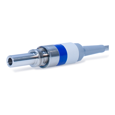
Emtec SonoTT User manual

SonoTTTM Clamp-On Transducer
Operating Instructions

Copyright
All rights reserved, especially with respect to reproduction, distribution and translation.
These operating instructions or any part thereof must not be reproduced, saved, processed, duplicated or
distributed without the written consent of em-tec GmbH.
© Copyright 2022 em-tec GmbH Finning. -All rights reserved.
Subject to Technical Changes
Owing to our policy of continuous product development, the illustrations and technical data contained in
this document may differ slightly from the current version of the device.
Legal Manufacturer
em-tec GmbH
Lerchenberg 20
86923 Finning
GERMANY
Phone: +49 8806 9236-0
Fax: +49 8806 9236-50
E-mail: em-tec-info@psgdover.com
Internet: www.em-tec.de

EN
Table of Contents
English..................................................... 5
Deutsch..................................................... 26
DE
SonoTTTM Clamp-On Transducer

EN
Table of Contents
1 System Description............................................................................................................5
2 Description of the Measurement Principle..................................................................6
3 General Safety Information, Symbols and Units ...................................................... 7
3.1 Symbols Used in these Operating Instructions ...................................................7
3.2 Symbols on the SonoTTTM Clamp-On Transducer and on Packaging.............7
4 General Information Concerning these Operating Instructions.............................8
5 Intended Purpose, Restrictions and Limitations.......................................................8
5.1 Intended Purpose.........................................................................................................8
5.2 Contraindications......................................................................................................... 9
5.3 Usage Restrictions and Limitations........................................................................ 9
5.4 Liabilities and Responsibilities.............................................................................. 10
5.5 Notice Concerning Compulsory Registration..................................................... 10
5.6 Safety Instructions..................................................................................................... 10
5.7 Electromagnetic Compatibility .............................................................................. 10
5.8 Ultrasonic Safety Regarding Acoustic Output.....................................................11
5.9 Biocompatibility ..........................................................................................................11
5.10 Maintenance and Service..........................................................................................12
6 Installation, Use, and Disassembly of the
SonoTTTM Clamp-On Transducer....................................................................................13
6.1 General Safety Information .....................................................................................13
6.2 Connecting the SonoTTTM Clamp-On Transducer to the
SonoTTTM Ultrasonic FlowComputer.......................................................................13
6.3 Attaching the SonoTTTM Clamp-On Transducer to the Tube........................... 14
6.4 Use of the SonoTTTM Clamp-On Transducer.........................................................15
6.5 Disassembly and Storage of the SonoTTTM Clamp-On Transducer ............ 16
6.6 Cleaning and Disinfection of the SonoTTTM Clamp-On Transducer..............17
6.7 Changing the SonoTTTM Clamp-On Transducer .................................................17
7 Adjustment and Calibration of the SonoTTTM Clamp-On Transducer...................18
7.1 Adjustment................................................................................................................... 18
7.2 Calibration ................................................................................................................... 18
8 Troubleshooting ...............................................................................................................19
9 Environmental Protection and Disposal.....................................................................22
10 TechnicalSpecicationsoftheSonoTTTM Clamp-On Transducer.........................23
SonoTTTM Clamp-On Transducer
Page 4 D162-700 SonoTTTM Clamp-On Transducer - Operating Instructions V3.0 Copyright em-tec GmbH

EN
1 System Description
The SonoTTTM Clamp-On Transducer, which is used in combination with, and powered by, the evaluation
device SonoTTTM Ultrasonic FlowComputer, measures the volumetric ow rate of uids based on the ultrasonic
transit time method. The SonoTTTM Clamp-On Transducer encloses exible tubes via a simple click-fastening
and operates non-invasively without physical contact to the medium, allowing it to meet even strict hygienic
requirements. In combination, the SonoTTTM Clamp-On Transducer and the SonoTTTM Ultrasonic FlowComputer
represent an independent system.
Established elds of application on extracorporeal tubing circuits for the SonoTTTM Clamp-On Transducer are,
for example:
• heart-lung machines (HLM)
• extracorporeal membrane oxygenation (ECMO)
• organ perfusion
• left and right ventricular bypasses
• cardiopulmonary support/bypasses
• venous extracorporeal support (e.g. for liver transplantation)
• shunts
ClassicationunderMDR(EUDirective2017/745)
The SonoTTTM Clamp-On Transducer is assigned to MDR Class I in accordance with Annex VIII, using Rule 13.
The SonoTTTM Clamp-On Transducer is an active device used to monitor the ow in extracorporeal tubing
circuits together with the SonoTTTM Ultrasonic FlowComputer. The Declaration of Conformity for the MDR is
based on this classication.
While a copy of the current version of the CE Declaration of Conformity, including RoHS and REACH, and
a copy of the CE certicate itself are not included in these operating instructions, they are available from
em-tec GmbH upon request.
Figure 1: SonoTTTM FlowMeasurement System
SonoTTTM Clamp-On Transducer
Copyright em-tec GmbH D162-700 SonoTTTM Clamp-On Transducer - Operating Instructions V3.0 Page 5

EN
2 Description of the Measurement Principle
The SonoTTTM Clamp-On Transducer is based on an acoustic measurement principle and utilizes the transit
time method to determine the ow. A typical transit time ow measurement system incorporates two
piezo ceramics that act as both ultrasonic transmitter and receiver. The measurement system, consisting
of the SonoTTTM Ultrasonic FlowComputer and the SonoTTTM Clamp-On Transducer, operates by alternately
transmitting and receiving an ultrasonic pulse between the piezo ceramics and measuring the transit time
difference that it takes for the pulse to travel between them.
This method determines the transit time difference of ultrasonic signals through a measuring section
and is used to estimate volumetric ow rates. There are at least two piezo ceramics required in order to
send and receive ultrasonic pulses both with and against the ow direction. For a higher accuracy, the
SonoTTTM Clamp-On Transducers incorporate two pairs of piezo ceramics, i.e. four piezo ceramics in total,
which are arranged in an X-conguration around the tube containing the measured ow.
When sending ultrasonic signals through the measuring section, the transit time difference depends on the
ow direction of the medium:
• The ultrasonic sound signals that are sent along the ow direction and volume ow of the medium, i.e.
downstream, need less time to travel the measuring section
than
• the ultrasonic sound signals that are sent against the ow direction, i.e. upstream.
Consequently, the transit time difference is measured for every pulse. The difference between upstream and
downstream measurements is proportional to the volumetric ow rate of the liquid in the tube. Therefore,
by accurately measuring the difference between upstream and downstream transit time Tup and Tdown, it is
possible to estimate the ow velocity. Subsequently, the volumetric ow rate is computed from the inner cross
section area of the tube and the instrument coefcient.
Figure 2: Sensor Structure
SonoTTTM Clamp-On Transducer
Page 6 D162-700 SonoTTTM Clamp-On Transducer - Operating Instructions V3.0 Copyright em-tec GmbH

EN
3 General Safety Information, Symbols and Units
3.1 Symbols Used in these Operating Instructions
Symbol Meaning
Warning! This safety symbol precedes critical information that must be strictly
observed in order to prevent injuries and fatal hazards. This warning symbol is the
most important safety symbol.
Caution! Important information regarding correct handling. Must be observed and
strictly adhered to. If this information is not observed, malfunction or damage of
the product and its surroundings may occur.
3.2 Symbols on the SonoTTTM Clamp-On Transducer and on Packaging
Symbol Meaning
Read these operating instructions carefully before use. Keep them in an easily
accessible location for future reference. Replacement copies of these operating
instructions are available from the manufacturer.
Do not dispose of this device together with domestic waste!
The device as a whole as well as any parts must be disposed of in accordance with
WEEE Directive and national legislation.
Manufacturer:
em-tec GmbH · Lerchenberg 20 · 86923 Finning · Germany
Date of manufacture
Serial number
Order number
Temperature limit during storage and transport.
Moisture limit during storage and transport.
Air pressure limit
Classication Applied Part: BF according to EN 60601-1
IP67 IP (=Ingress Protection) Classication
SonoTTTM Clamp-On Transducer
Copyright em-tec GmbH D162-700 SonoTTTM Clamp-On Transducer - Operating Instructions V3.0 Page 7

EN
4 General Information Concerning these Operating Instructions
• Read these operating instructions carefully before starting up the system!
→This document is intended for the SonoTTTM Clamp-On Transducer and describes
the use of the SonoTTTM Clamp-On Transducer in combination with the
SonoTTTM Ultrasonic FlowComputer.
• The user (= the person who connects the SonoTTTM Clamp-On Transducer to
the tubing circuit and measurement system) is responsible for any risk if the
SonoTTTM Clamp-On Transducer is not connected correctly.
• Inspect your SonoTTTM Clamp-On Transducer for completeness and damage when unpacking
it for the rst time.
• The customer must ensure that the persons involved in the integration and use of the
SonoTTTM Clamp-On Transducer and the system it is part of are adequately qualied. In
addition, the information in these operating instructions must be followed.
• Do not drop the SonoTTTM Clamp-On Transducer. It might break or become damaged, which
could impair the measurement.
These instructions contain important information concerning the safe and correct handling of the
SonoTTTM Clamp-On Transducer. Read these operating instructions carefully before using the product and keep
them in an easily accessible location. Familiarize yourself with all warning and safety information and observe
them. It is the responsibility of the operator to ensure that the SonoTTTM Clamp-On Transducer is used, inspected
and maintained in accordance with the operating instructions. This also applies for all subsequent revisions or
instructions from the manufacturer. The manufacturer reserves the right to modify technical data without
prior notice.
5 Intended Purpose, Restrictions and Limitations
5.1 Intended Purpose
The SonoTTTM Clamp-On Transducer (in combination with a SonoTTTM Ultrasonic FlowComputer) is indicated for
the bi-directional volumetric measurement of the liquid owing through tubing systems. The measurement
principle is the ultrasound transit-time method.
The medical use of the device is appropriate for extracorporeal applications together with the
SonoTTTM Ultrasonic FlowComputer such as:
• cardio-pulmonary bypass, hemodialysis, hemoltration, plasmapheresis
• ECMO (ExtraCorporeal Membrane Oxygenation) applications
• perfusion, infusion, transfusion
• several shunt-applications
Intended Users of the SonoTTTM Clamp-On Transducer
For reasons of patient safety, the device may only be used by qualied and trained medical professionals.
SonoTTTM Clamp-On Transducer
Page 8 D162-700 SonoTTTM Clamp-On Transducer - Operating Instructions V3.0 Copyright em-tec GmbH

EN
Intended Patients of the SonoTTTM Clamp-On Transducer
The product is intended for the following patient population:
• patients who are undergoing a surgery, supervised by medically trained personnel.
• patients who are connected to an extracorporeal circulation system such as an ECMO device.
• patients who are treated within an hospital environment, e.g. an intensive care unit or operating room.
The product is not intended for the direct use on patients and should not come into direct contact with
them. In situations where skin contact cannot be ruled out or avoided, a pad, e.g. a gauze, should be placed
between the skin and the sensor.
A malfunction of the device is causing no additional health risk to the patient.
Intended Environment of the SonoTTTM Clamp-On Transducer
The SonoTTTM Clamp-On Transducer is designed for the continuous operation in intensive care units, operating
rooms and similar medical environments.
ClinicalBenets
Additional information for the attenting physician on the ow behavior of liquids in a patient-bound tubing
system.
The expected lifetime of the device is ten years.
5.2 Contraindications
This device and the accessories have been built and sold exclusively for the intended purpose mentioned
above.
The SonoTTTM Clamp-On Transducer and the SonoTTTM Ultrasonic FlowComputer are explicitly not intended
–to allow direct diagnosis or monitoring of vital physiological processes.
–for the monitoring of vital physiological parameters, where the variation could result in immediate
danger to the patient, for instance variations in cardiac performance, respiration, activity of the central
nervous system.
–as sole base for decisions regarding therapeutic methods. The values issued by this device have to
always be veried with other methods before any decisions regarding treatment are made.
It is the operator’s responsibility to use the device as described in the operating instructions and in any of its
following revisions. The use of clinical procedures and techniques lies in the physician’s area of responsibility.
5.3 Usage Restrictions and Limitations
The SonoTTTM Clamp-On Transducer is explicitly not intended
–for the use outside of medical environments.
–for the use inside means of medical transport (e.g. ambulance car or helicopter).
SonoTTTM Clamp-On Transducer
Copyright em-tec GmbH D162-700 SonoTTTM Clamp-On Transducer - Operating Instructions V3.0 Page 9

EN
5.4 Liabilities and Responsibilities
The user is responsible to use, check and maintain the SonoTTTM Clamp-On Transducer according to these
operating instructions.
em-tec GmbH is neither liable nor responsible for any consequences arising from the use of the
SonoTTTM Clamp-On Transducer that does not comply with the operating instructions or specications in this
document.
5.5 Notice Concerning Compulsory Registration
Any major incidents in any ways connected to the product must be immediately reported to the manufacturer
and the appropriate authority of the member state in which the user and/or patient reside in.
5.6 Safety Instructions
If the SonoTTTM Clamp-On Transducer is part of a medical application, the user has to observe the following
instructions:
• The measured values of the SonoTTTM Clamp-On Transducer, supplied through the corresponding evaluation
device (i.e. the SonoTTTM Ultrasonic FlowComputer) only display the current ow rate (e.g. of an oxygenator
or blood pump).
• These values are neither to be used for the evaluation of a patient’s status nor for the basis of medical
actions without the conrmation of another approved medical measurement procedure.
• Should the unit be used to control the liquid volume ow, the user has to analyze the risk of the application
and, if necessary, take additional actions independent from the system to minimize this risk.
5.7 Electromagnetic Compatibility
Medical electronic devices are subjected to special precautions in terms of the electromagnetic compatibility
(EMC). Because of this, the SonoTTTM Clamp-On Transducer and SonoTTTM Ultrasonic FlowComputer have to be
installed and operated according to the following EMC information.
The SonoTTTM Ultrasonic FlowComputer and the SonoTTTM Clamp-On Transducer fulll the requirements of
the
IEC 60601-1-2 4
th
ed.
. Compliance with these requirements can only be guaranteed if the device is used
according to the operating instructions.
This device fullls the requirements of Class A according to CISPR 11 and should not be operated in home
care, industrial areas, or environments with strong electromagnetic elds or disturbances.
Portable RF communications equipment (including peripherals such as antenna cables and external
antennas) should be used no closer than 30 cm (12 inches) to any part of the SonoTTTM Clamp-On Transducer
or SonoTTTM Ultrasonic FlowComputer including the cables. Otherwise, degradation of the measurement
performance and stability of this equipment could result.
If an electric cautery comes in contact with the device or the SonoTTTM Ultrasonic FlowComputer, it might
cause a dysfunction which can lead to incorrect measurement values or other problems. This includes use
of HF surgery at the patient or crossing of lines. Increased emission or decreased electromagnetic noise
immunity can affect the measurements.
SonoTTTM Clamp-On Transducer
Page 10 D162-700 SonoTTTM Clamp-On Transducer - Operating Instructions V3.0 Copyright em-tec GmbH

EN
They can be caused by the use of SonoTTTM Clamp-On Transducers or any devices and/or accessories that are
part of the measurement system but which are not mentioned in these operating instructions. Interference
of ultrasonic ow measurements by electromagnetic elds could be possibly identied by compromised
measured data, which are not related to the real ow. Please also note that the SonoTTTM Clamp-On Transducer
is not galvanically isolated.
The SonoTTTM Clamp-On Transducer performs without producing either unintended or excessive ultrasound
output nor unintended or excessive surface temperatures according to
IEC 60601-1-2 4
th
ed.
Electromagnetic
elds and electrostatic discharge cannot lead to unintended changes of the electronics causing hazardous
ultrasonic output. Nevertheless, it is important to ensure that the SonoTTTM Clamp-On Transducer and the
SonoTTTM Ultrasonic FlowComputer are not placed near any disturbance source that is not compliant with the
applicable standards, since this could inuence and negatively affect the measurement.
5.8 Ultrasonic Safety Regarding Acoustic Output
When in use, the connected SonoTTTM Clamp-On Transducers produce very low-power ultrasonic signals at
frequencies between 2.25 and 4 MHz. The emmited acoustic signals are declared in the technical specications
according to
IEC 61157 2
nd
ed.
and
IEC 60601-2-37 2
nd
ed.
If used properly, the acoustic signals produced by the SonoTTTM Ultrasonic FlowComputer and
SonoTTTM Clamp-On Transducer are, according to current knowledge, harmless for people and the environment.
5.9 Biocompatibility
The SonoTTTM Clamp-On Transducer is made from conventional materials which, with appropriate use, are
harmless for the patient and the user according to current knowledge.
SonoTTTM Clamp-On Transducer
Copyright em-tec GmbH D162-700 SonoTTTM Clamp-On Transducer - Operating Instructions V3.0 Page 11

EN
5.10 Maintenance and Service
The service for the SonoTTTM Clamp-On Transducer may be carried out by
em-tec GmbH only. If these instructions are not followed, em-tec GmbH shall accept no liability for the
component and the warranty will be void.
In order to maintain the accuracy of the SonoTTTM Clamp-On Transducer, it is recommended to regularly carry
out re-calibrations. The time between calibrations should not exceed 24 months.
If you experience any trouble with the measurement despite following the operating instructions, or if your
SonoTTTM Clamp-On Transducer is damaged in any way, please contact our service department.
Please make a note of the serial number of the SonoTTTM Clamp on Transducer and the evaluation device
before you contact our staff.
If you need to return the SonoTTTM Ultrasonic FlowComputer or the SonoTTTM Clamp-On Transducer for
servicing, please follow the steps below:
1. Contact our service department at:
em-tec GmbH
Service Department
Am Graben 6-8
86923 Finning
Germany
em-tec-service@psgdover.com
2. Our service department will send you a RMA form.
3. Fill out the form and include it in your shipment.
SonoTTTM Clamp-On Transducer
Page 12 D162-700 SonoTTTM Clamp-On Transducer - Operating Instructions V3.0 Copyright em-tec GmbH

EN
6 Installation, Use, and Disassembly of the
SonoTTTM Clamp-On Transducer
6.1 General Safety Information
• If the SonoTTTM Clamp-On Transdcuer is not used as intended, the user may be exposed to
risks that were not taken into account during its development.
• If the SonoTTTM Clamp-On Transducer is clamped onto a tubing circuit that is part of a
life-supporting device used to maintain a patient's bodily functions, to support the lives
of critically-ill patients, or during surgical interventions, these devices must be used and
monitored by qualied clinical professionals.
• Decisions regarding therapeutic methods must not be solely based on the measured ow
data.
• The values issued by the ow measuremet system including the SonoTTTM Clamp-On
Transducer have to always be veried with other methods before any decisions regarding
treatment are made.
• For the installation, all ambient conditions must meet the prescribed specications (see
chapter 10 “Technical Specications of the SonoTTTM Clamp-On Transducer”).
6.2 Connecting the SonoTTTM Clamp-On Transducer to the
SonoTTTM Ultrasonic FlowComputer
To connect the SonoTTTM Clamp-On Transducer to the SonoTTTM Ultrasonic FlowComputer, carefully attach the
15-pin high density D-Sub socket to the screw connection at the back of the SonoTTTM UltrasonicFlowComputer.
Once this is done, the sensor can be attached to the tube.
• The connector of the SonoTTTM Clamp-On Transducer must be dry when plugged in.
• Check the plug and the pins for damage before connecting the sensor.
• Do not use the SonoTTTM Clamp-On Transducer if any part of it is damaged.
• Check and make sure that the connector used ts and is actually compatible with the
measurement system.
SonoTTTM Clamp-On Transducer
Copyright em-tec GmbH D162-700 SonoTTTM Clamp-On Transducer - Operating Instructions V3.0 Page 13

EN
6.3 Attaching the SonoTTTM Clamp-On Transducer to the Tube
• Before you clamp on the sensor, make sure that the tube is not deformed, damaged, or dirty.
• Air in the tube can lead to errors in the measurement or interrupt the ultrasound coupling.
• Ensure that there is no debris or dirt in the ow channel. If necessary, clean the ow channel
before attaching the SonoTTTM Clamp-On Transducer to the tube.
• While installing the SonoTTTM Clamp-On Transducer, be sure not to impair the function of
the tubing system.
• Ensure that the tube size and material used corresponds with the size and material the
SonoTTTM Clamp-On Transducer was calibrated and adjusted for.
• First, make sure that the arrow on the lid is aligned with the ow direction (positive ow
display).
Note: If the medium within the tube moves in the opposite direction of the arrow on the
lid, the ow value is displayed as negative value (e.g. -250 ml/min instead of 250 ml/min).
The accuracy and the ow range stated in chapter 10 "Technical Specications of the
SonoTTTM Clamp-On Transducer" remains the same for both positive and negative values.
To clamp on the SonoTTTM Clamp-On Transducer, follow the steps illustrated below:
1. Open the spring-loaded lock and swing back the lid.
2. Insert the tube into the channel.
3. Close the SonoTTTM Clamp-On Transducer lid and secure it with the help of the spring-loaded lock.
• Do not use excessive force when closing the sensor lid; while the tube should be xed within
the channel, it must not be crammed into it as this might affect the measurement values or
damage the sensor.
• Ensure that the lid is fully closed as to avoid uctuating coupling and ow values.
• To avoid ow turbulances and associated measurement inaccuracies, it is necessary for the
tube to be straight in the area near the SonoTTTM Clamp-On Transducer.
• Ideally, the tube should be straight for a distance of at least 10 x the inner diameter (ID) of
the tube on either side of the sensor.
Figure 3: Clamping on the Sensor
Figure 4: Ideal Inlet Section
SonoTTTM Clamp-On Transducer
Page 14 D162-700 SonoTTTM Clamp-On Transducer - Operating Instructions V3.0 Copyright em-tec GmbH

EN
For more information regarding the setup of the SonoTTTM Clamp-On Transducer and what to keep
in mind to maintain and optimize the accuracy of your flow measurementent, refer to our TechNote
"Optimizing Accuracy". The TechNote is available upon request, or for download on our website.
6.4 Use of the SonoTTTM Clamp-On Transducer
For more details on how to carry out the ow measurement, please refer to the operating
instructions of the evaluation device; in this case, the SonoTTTM Ultrasonic FlowComputer.
Make sure to follow the steps below and to heed the instructions included in them in order to
ensure the highest possible accuracy of measurement values as well as the highest possible
safety for the patient.
In addition, always ensure that
• the medium temperature is the temperature the sensor was calibrated and adjusted for.
• there is a zero ow adjustment performed before each measurement.
• the sensor is not permanently placed on the patient as this might lead to skin irritations.
Beforestartingtheowmeasurement:
1. Make sure that only tubes specied for the SonoTTTM Clamp-On Transducer are used as this is the tube type
the SonoTTTM Clamp-On Transducer is adjusted and calibrated for.
2. Before each measurement, the cables, connectors and pins must be checked for breaks or
damages as this could result in wrong measurements. If there are any damages, do not use the
SonoTTTM Clamp-On Transducer.
3. Ensure that the temperature of the medium is the one the SonoTTTM Clamp-On Transducer was adjusted
and calibrated for.
4. Ensure that no air bubbles are in the tube during the zero ow adjustment. Allow sufcient time for the
system to adapt to ambient conditions, then zero the ow. Only then is the system ready for measurement.
5. The coupling must be checked before each measurement.
6. Azeroowadjustmentmustbecarriedoutbeforeeachmeasurement to avoid possible offsets from the
measured values.
Beforethezeroowadjustment, allow the system sufcient time to adapt to ambient conditions.
Duringthezeroowadjustment,
–The sensor must be clamped on the correct position .
–The tube must be lled with liquid, but the liquid must not move.
–There must be no air bubbles inside the tube.
Duringtheowmeasurement:
• Ensure that the coupling is within the operating range of 60 % - 99%. If the coupling falls below 50 %, the
SonoTTTM Ultrasonic FlowComputer issues a warning as the low coupling might impair the measurement.
• It is important that any unwanted interruption of the extracorporeal patient circulation due to damage or
kinking of the tubing is avoided at all times.
• The stated measurement accuracy of the SonoTTTM Clamp-On Transducer is only valid if the specied tubes
are used and if the temperature of the medium is the one the sensor was adjusted and calibrated for.
• Any changes in the medium itself or its temperature can cause errors or anomalies in the measurement.
• It must be ensured that the correct calibration parameters are used.
SonoTTTM Clamp-On Transducer
Copyright em-tec GmbH D162-700 SonoTTTM Clamp-On Transducer - Operating Instructions V3.0 Page 15

EN
While it is possible to carry out measurements outside of the specied ow range, em-tec GmbH cannot
guarantee that resulting ow values will be within the given accuracy range.
The parameters of the connected SonoTTTM Clamp-On Transducer and the selected calibration table are
displayed in the Settings-Menu of the SonoTTTM Ultrasonic FlowComputer as shown in the following example:
Calibration
Table Transdcuer
Serial No. Tube Size Tube
material Medium Medium
Temperature Maximum Measured Value
0 SN 12345 3/8" x 3/32" PVC Blood
(based on water) 37 °C (98.6 °F) 10000 ml/min
Pleasue ensure that the tube size and material used corresponds to that shown on the display of the SonoTTTM Ultrasonic FlowComputer.
6.5 Disassembly and Storage of the SonoTTTM Clamp-On Transducer
In order to not impair the measurement, it is best to disassemble the SonoTTTM Clamp-On
Transducer once the measurement process has been completed.
To disconnect the SonoTTTM Clamp-On Transducer, follow these steps:
1. Open the spring-loaded lock and swing back the lid.
2. Remove the tube from the channel.
3. Close the lid and carefully remove the 15-pin, high density D-Sub socket from the screw connection at the
back of the SonoTTTM Ultrasonic FlowComputer.
Once you have disconnected the SonoTTTM Clamp-On Transducer, check for any residue of the medium or
any other kind of dirt or grime and clean the sensor if necessary. Store the sensor according to storage
specications. Make sure to store it in a place where it cannot fall off or be dropped and ensure that the plug
is dry.
SonoTTTM Clamp-On Transducer
Page 16 D162-700 SonoTTTM Clamp-On Transducer - Operating Instructions V3.0 Copyright em-tec GmbH

EN
6.6 Cleaning and Disinfection of the SonoTTTM Clamp-On Transducer
Make sure no detergents, disinfectants or other liquids can leak into the plug of the
SonoTTTM Clamp-On Transducer.
For the cleaning of the device, we recommend the use of common household detergents. In order to avoid
stains and dirt from drying out, grime residue should be removed after each application.
To clean the SonoTTTM Clamp-On Transducer, use a lint-free cloth. Be sure to remove any dirt in the clamping
area. Additionally, please follow the legal regulations valid in your country and the hygiene regulations for
your doctor’s ofce or hospital.
•The SonoTTTM Clamp-On Transducer may not be submerged into cleaning or disinfecting
solution.
•The SonoTTTM Clamp-On Transducer is not suited for cleaning processes using machines.
Sterilization processes, especially steam sterilization or autoclaving, may not be used.
•The SonoTTTM Ultrasonic FlowComputer and the SonoTTTM Clamp-On Transducer are used
in non-sterile areas in operating rooms. Due to this, cleaning and disinfection after every
use as well as before the rst use is essential.
The following surface disinfectant is recommended:
Name Manufacturer Contact
Bacillol® AF Hartmann www.hartmann.de
6.7 Changing the SonoTTTM Clamp-On Transducer
If the SonoTTTM Clamp-On Transducer was exchanged before switching on the
SonoTTTM Ultrasonic FlowComputer, then the new calibration parameters will be shown in the Settings Menu
of the SonoTTTM Ultrasonic FlowComputer after the next start-up sequence.
If the SonoTTTM Clamp-On Transducer is exchanged during the operation of the SonoTTTM Ultrasonic
FlowComputer, the alarm is activated with an error message. Once the new SonoTTTM Clamp-On Transducer is
connected, the alarm is reset and the calibration data can be seen in the Settings Menu.
• Make sure that the SonoTTTM Clamp-On Transducer is attached at a different place on the
tube each time to avoid deformation.
• Ensure that the calibration table used is the one needed for your respective application.
SonoTTTM Clamp-On Transducer
Copyright em-tec GmbH D162-700 SonoTTTM Clamp-On Transducer - Operating Instructions V3.0 Page 17

EN
7 Adjustment and Calibration of the SonoTTTM Clamp-On Transducer
As the function of the SonoTTTM Clamp-On Transducer is based on an acoustic measurement principle,
parameters such as the tubing size and material, or the medium as well as its temperature can impact the
ultrasonic signal and thus the transit time difference between them. To take these factors into account and
to ensure the highest possible accuracy regarding the measured values, each sensor is individually adjusted
and calibrated prior to shipment.
The relevant parameters for the adjustment and calibration are:
–tubing material
–medium
–medium temperature
–flow range
7.1 Adjustment
An act of modifying something, in this case to fit a certain standard, the sensor adjustment represents an
actual intervention in the measurement system. To ensure that the parameters stated above are factored
into the measurement and consequently into the ow values displayed by the SonoTTTM Ultrasonic
FlowComputer, parameters such as the amplitude of the ultrasonic signal or the length of the ultrasonic burst
are changed to t the tubing and the medium used during the application. .
As a result, the adjustment is an action that permantently alters the
device as the setting of the burst signal (scan window and amplitude)
and the sequential balance line are changed.
Since these parameters have a deep impact on the sensor‘s
performance, and since adjusting the sensor represents an intervention
of the measurement system, adjustments may only be carried out by
em-tec GmbH.
7.2 Calibration
The term ‘calibration‘, on the other hand, refers to the act of checking the accuracy of a measurement device
by comparing its measurement values with those of a device with a known accuracy. This comparison is
subject to a specied measurement setup and specied measurement conditions. During the calibration
process, neither the devices involved nor any of their parameters may be changed, manipulated, or altered
in any way.
Ideally, the SonoTTTM Clamp-On Transducers should be re-calibrated every 24 months. This can be carried out
by the customer on-site or by em-tec GmbH.
For more information regarding this process, please contact em-tec GmbH:
Figure 5: Ultrasonic Signal
SonoTTTM Clamp-On Transducer
Page 18 D162-700 SonoTTTM Clamp-On Transducer - Operating Instructions V3.0 Copyright em-tec GmbH

EN
8 Troubleshooting
If there are any issues with the SonoTTTM Clamp-On Transducer, try the following suggestions. If the problem
cannot be solved this way, please contact your local distributor or em-tec GmbH directly.
Problem Possible Cause Action
Sensor lid does not
close.
• Sensor might be
damaged.
• Tube might be too
large.
1. Check if the sensor is damaged.
2. Check if the tube size is the one indicated for your
sensor.
3. If necessary, exchange the tube for the right one.
If the problem persists, return the sensor for servicing*.
Sensor does not
stay in place.
• Sensor might be
damaged.
• Tube might be too
small.
1. Check if the sensor is damaged.
2. Check if the tube size is the one indicated for your
sensor.
3. If necessary, exchange the tube for the right one.
If the problem persists, return the sensor for servicing*.
Sensor emits noise.
There might be
electromagnetic elds
inuencing the sensor.
1. Check if there are any electromagnetic elds or
disturbance sources that are not compliant with
the relevant standards and that could inuence the
sensor. Also check if the sensor or its cable came into
contact with an electric cautery.
2. Remove the source of the electromagnetic eld or
carry the measurement out somewhere else.
If the problem persists, return the sensor for servicing*.
Sensor is not
recognized.
There is no
measurement
possible.
The cable is damaged.
1. Check if the sensor is connected properly to the
device and if the sensor is damaged.
2. Check if the cable is damaged.
3. If the cable is damaged, return the sensor and cable
for servicing.
If the problem persists, return the sensor for servicing*.
The plug is damaged (e.g.
broken PIN).
1. Check if the sensor is connected properly to the
device and if the sensor is damaged.
2. Check if the plug is damaged and if there are any
broken PINs
3. If the plug is damaged, return the device for servicing.
If the problem persists, return the sensor for servicing*.
SonoTTTM Clamp-On Transducer
Copyright em-tec GmbH D162-700 SonoTTTM Clamp-On Transducer - Operating Instructions V3.0 Page 19

EN
Problem Possible Cause Action
Sensor is not
recognized.
There is no
measurement
possible.
Storage might have been
damaged or deleted by
electromagnetic elds.
1. Check if the sensor is connected properly to the
device and if the sensor is damaged.
2. Check if there are any electromagnetic elds or
disturbance sources that are not compliant with
the relevant standards and that could inuence the
sensor.Also check if the sensor or its cable came into
contact with an electric cautery.
3. Remove the source of the electromagnetic eld or
carry the measurement out somewhere else.
If the problem persists, return the sensor to em-tec GmbH
for recalibration*.
The connected sensor is
the wrong sensor type.
1. Check if the correct sensor is connected and if the
connected sensor is not damaged.
2. If the sensor is correct, disconnect it.
3. Reconnect the sensor again.
If the problem persists, return the device and sensor for
servicing,
Acoustic coupling is
too low.
Sensor lid might not be
closed properly.
1. Check if the sensor lid is closed properly.
2. Close the lid.
If the problem persists, return the sensor for servicing*.
The tube size and/or
material is not the one
indicated for the sensor.
1. Check if the tube size and material are the ones the
sensor was adjusted and calibrated for.
2. If necessary, exchange the tube for the right one.
If the problem persists, return the sensor for servicing*.
There is dirt in the ow
channel.
1. Check if there is dirt in the ow channel.
2. If necessary, clean the ow channel.
If the problem persists, return the sensor for servicing*.
Sensor might be
damaged.
1. Check if the sensor or the sensor lid is damaged
(e.g. broken hinge).
2. If the sensor is damaged, stop the measurement and
return the sensor for servicing.
If the problem persists, return the sensor for servicing*.
There are air bubbles in
the tube.
1. Check if there are air bubbles in the tube.
2. Remove any air within the tube.
3. Repeat the ow measurement following the steps
described in chapter 6.4.
If the problem persists, return the sensor for servicing*.
SonoTTTM Clamp-On Transducer
Page 20 D162-700 SonoTTTM Clamp-On Transducer - Operating Instructions V3.0 Copyright em-tec GmbH
Table of contents
Languages:
Popular Transducer manuals by other brands
Setra Systems
Setra Systems 269 installation guide

novotechnik
novotechnik TP1 Series user manual
Balluff
Balluff BTL5-P1 Series user guide
Camille Bauer
Camille Bauer SINEAX I 538 operating instructions
Shinkawa
Shinkawa CV-86 Series instruction manual

Airmar
Airmar P79S Owner's guide & installation instructions
Electro-Voice
Electro-Voice 3-Inch High Frequency Neodymium Transducer... Technical specifications
Humminbird
Humminbird Transducer Installation

Honeywell
Honeywell IPT user manual

Airmar
Airmar P58 Owner's guide & installation instructions
OHIO SEMITRONICS
OHIO SEMITRONICS DCT Series operating instructions
Simrad
Simrad 710-36E - REV E datasheet
