manuals.online logo
Brands
  1. Home
  2. •
  3. Brands
  4. •
  5. novotechnik
  6. •
  7. Transducer
  8. •
  9. novotechnik TP1 Series User manual

novotechnik TP1 Series User manual

TP1 Gebrauchsanleitung
TP1 User manual
402518885/14 Änderungen vorbehalten / Subject to change 2022/12 Seite 1
1Allgemeine Beschreibung 2
2Sicherheitshinweise 2
2.1 Bestimmungsgemäße Verwendung 2
2.2 Installation & Inbetriebnahme 2
2.3 Anschlüsse prüfen 2
2.4 Einschalten des Systems 2
2.5 Messwerte prüfen 2
2.6 Funktionsfähigkeit prüfen 2
2.7 Funktionsstörung 2
2.8 Entsorgung 2
3Elektrische Daten 3
4Montagehinweis 3
5Anschlüsse 3
6Einbau und Installation 4
6.1 Wegaufnehmer 4
6.2 Positionsgeber 5
6.2.1 Z-TP1-P06 5
6.2.2 Z-TP1-P07 5
6.2.3 Z-TP1-P08 5
7Elektrischer Anschluss 6
7.1 Code 101/103/108 6
7.2 Code 102/107 6
7.3 Code 201/203/205 6
7.4 Polbild 7
8Schnittstellen und Anschlussbelegung 8
8.1 Impuls-Schnittstelle 8
8.2 SSI-Schnittstelle 8
8.3 Inkrementale Schnittstelle 9
8.4 Analoge Schnittstellen 10
8.5 IO-Link Schnittstelle 10
9Spezifische Stecker auf Anfrage 11
9.1 6-pol. Flanschstecker 11
9.2 12-pol. Flanschstecker 11
9.3 5-pol. Flanschstecker 11
10 Teach-In Funktion 11
11 Versatz des Positionsgebers 13
11.1 Fehlermeldung Positionsgeber 13
12 Optionales Zubehör 14
13 Bestellcode 14
14 Produktidentifikation 14
1General description 2
2Safety instructions 2
2.1 Intended conditions of use 2
2.2 Installation & startup 2
2.3 Check connections 2
2.4 Turning on the system 2
2.5 Check measured values 2
2.6 Check functionality 2
2.7 Failure malfunction 2
2.8 Disposal 2
3Electrical data 3
4Instruction for installation 3
5 Wiring 3
6Mounting and installation 4
6.1 Transducer 4
6.2 Position marker 5
6.2.1 Z-TP1-P06 5
6.2.2 Z-TP1-P07 5
6.2.3 Z-TP1-P08 5
7Electrical connection 6
7.1 Code 101/103/108 6
7.2 Code 102/107 6
7.3 Code 201/203/205 6
7.4 Contact arrangement 7
8Interfaces and Connection Assignment 8
8.1 Impulse interface 8
8.2 SSI interface 8
8.3 Incremental interface 9
8.4 Analog output 10
8.5 IO-Link interface 10
9Special connectors on request 11
9.1 6 pin flange connector 11
9.2 12-pin flange connector 11
9.3 5 pin flange connector 11
10 Teach-In function 11
11 Displacement of the position marker 13
11.1 Error conditions position marker 13
12 Optional accessories 14
13 Ordering code 14
14 Product identification 14
TP1 Gebrauchsanleitung
TP1 User manual
1General description
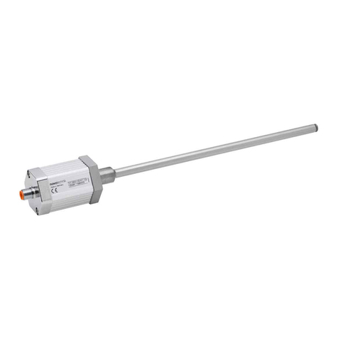
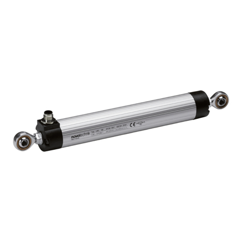
The TP1 series is a magnetostricitve transducer for direct,
accurate measurement of travel in display- or feedback
applications.
2Safety instructions
Our products are regularly not approved for aeronautic or
aerospace applications and are not allowed to be used in
nuclear or military, in particular ABC-relevant applications.
For more information see our Terms and Conditions.
2.1 Intended use
The transducer is intended to be installed in a machine or
system. Together with a controller (e.g. PLC) it comprises a
position measuring system and may only be used for this
purpose.
Unauthorized modifications, improper usage or non-
observance of the instructions for installation will result in
the loss of warranty and liability claims.
2.2 Installation & startup
The transducer must be installed by qualified personnel in
consideration of all relevant safety regulations.
All necessary safety measures to protect personnel and
property in case of a transducer defect or failure must be
taken before startup.
2.3 Check connections
Improper connections and overvoltage can damage the
transducer.
Check the connections always carefully before turning-on
system.
Potential differences between supply voltage
GND and signal GND must be avoided.
With different potentials between supply voltage
GND and signal GND the transducer can be
destroyed!
2.4 Turning on the system
The system may execute uncontrolled movements
during first turning-on mainly when the transducer is
part of a control system whose parameters have not
yet been set. Therefore make sure that hereof no
dangers for personal and property can result.
2.5 Check measured values
After replacement of a transducer, it is advisable to verify
the output values for start- and end position of the position
marker in manual mode.
(Transducers are subject to modification or manufacturing
tolerances)
2.6 Check functionality
The functionality of the transducer and all its associated
components should be regularly checked and recorded.
2.7 Failure malfunction
If the transducer doesn‘t operate properly, it should be
taken out of service and protected against unauthorized
use.
2.8 Disposal
Observe the national regulations for disposal.
1Allgemeine Beschreibung
Die Baureihe TP1 ist ein magnetostriktiver Wegaufnehmer
für die direkte, genaue und absolute Messung von Wegen
bzw. Längen in der Steuerungs-, Regelungs- und
Messtechnik.
2 Sicherheitshinweise
Unsere Produkte sind regelmäßig nicht für Luft- und
Raumfahrtanwendungen zugelassen und dürfen nicht
in kerntechnischen oder militärischen, insbesondere
ABC-relevanten Applikationen verwendet werden.
Weitere Informationen s. unsere AGBs.
2.1 Bestimmungsgemäße Verwendung
Der Wegaufnehmer wird zu seiner Verwendung in eine
Maschine oder Anlage eingebaut. Er bildet zusammen mit
einer Steuerung (z.B. SPS) ein Wegmesssystem und darf
auch nur für diese Aufgabe eingesetzt werden.
Unbefugte Eingriffe, nicht bestimmungsgemäße
Verwendung oder Nichtbeachtung der Montagehinweise
führen zum Verlust von Gewährleistungs-, Garantie- und
Haftungsansprüchen.
2.2 Installation & Inbetriebnahme
Der Wegaufnehmer ist nur von Fachpersonal und unter
Berücksichtigung aller geltenden Sicherheitsvorschriften
in Betrieb zu nehmen.
Alle Maßnahmen zum Schutz von Personen und Sachen
bei einem Defekt des Wegaufnehmers müssen vor der
Inbetriebnahme getroffen werden.
2.3 Anschlüsse prüfen
Falsche Verbindungen und Überspannung können zur
Beschädigung des Wegaufnehmers führen.
Prüfen Sie deshalb vor dem Einschalten die Anschlüsse
immer sorgfältig.
Potentialdifferenzen zwischen Versorgung GND
und Signal GND sind zu vermeiden.
Durch Potentialdifferenzen zwischen Versorgung
GND und Signal GND kann der Wegaufnehmer
zerstört werden!
2.4 Einschalten des Systems
Das System kann beim Einschalten unkontrollierte
Bewegungen ausführen, vor allem wenn der
Wegaufnehmer Teil eines Regelsystems ist,
dessen Parameter noch nicht eingestellt sind.
Stellen Sie daher sicher, dass hiervon keine
Gefahren für Personen und Sachen ausgehen
können.
2.5 Messwerte prüfen
Nach dem Austausch eines Wegaufnehmers wird
empfohlen, die Ausgangswerte in der Anfangs- und
Endstellung des Positionsgebers im Handbetrieb zu
überprüfen. (Änderungen oder fertigungsbedingte
Streuungen vorbehalten)
2.6 Funktionsfähigkeit prüfen
Die Funktionsfähigkeit des Wegaufnehmers und aller damit
verbundenen Komponenten sind regelmäßig zu überprüfen
und zu protokollieren.
2.7 Funktionsstörung
Wenn der Wegaufnehmer nicht ordnungsgemäß arbeitet,
ist es außer Betrieb zu nehmen und gegen unbefugte
Benutzung zu sichern.
2.8 Entsorgung
Die nationalen Vorschriften zur Entsorgung sind
einzuhalten.
402518885/14 Änderungen vorbehalten / Subject to change 2022/12 Seite 2
TP1 Gebrauchsanleitung
TP1 User manual
4Montagehinweis
Bei der Montage der Befestigungsklammern ist das
maximale Drehmoment von 200 Ncm zu beachten.
Es wird empfohlen, die Befestigungsklammern in
gleichmäßigen Abständen zu platzieren.
Der Positionsgeber (Zubehör) wird im Abstand laut Kap.6.2
zur Profiloberfläche montiert.
Die Aufnahme des Positionsgebers und die Befestigung
über Schrauben (M4) sollten über nichtmagnetisches
Material (z.B. Edelstahl, Messing, Aluminium) erfolgen.
Um die Genauigkeit des Wegaufnehmers zu
gewährleisten, muss der freie Positionsgeber parallel
zur Profiloberfläche geführt werden.
Starke elektrische oder magnetische Felder in
unmittelbarer Nähe des Wegaufnehmers
können zu fehlerhaften Signalen führen!
Der Mindestbiegeradius des Anschlusskabels ist
einzuhalten und scharfe Kanten sind zu vermeiden!
Bei Varianten mit mehreren Positionsgebern muss der
Abstand zwischen den Positionsgeber jeweils
min. 100 mm betragen! Das erste Positionssignal wird für
den Positionsgeber ausgegeben, der dem elektrischen
Abgang am nächsten ist.
5Anschlüsse
Beim elektrischen Anschluss unbedingt zu beachten:
Anlage (Versorgung GND) und Schaltschrank (Signal
GND) müssen auf gleichem Potential liegen.
Um die elektromagnetische Verträglichkeit (EMV) zu
gewährleisten, sind nachfolgende Hinweise unbedingt zu
beachten*:
•Wegaufnehmer und Steuerung müssen mit einem
geschirmten Kabel verbunden werden.
•Schirmung: Geflecht aus Kupfer-Einzeldrähten,
85% Bedeckung.
•Auf der Seite der Steuerung muss der Kabelschirm
geerdet, d.h. mit dem Schutzleiter verbunden werden.
•Eine Verlängerung des Anschlusskabels auf
> 30 m bedeutet den Verlust der CE-Freigabe !
*)Für Sensoren mit IO-Link Schnittstelle dürfen
ungeschirmte Verbindungsleitungen verwendet werden;
max. Leitungslänge 20 m.
4Instruction for installation
The maximum torque of 200 Ncm is to be considered by
assembling of the mounting clamps.
It is recommended to place the mounting clamps in
constant distances.
The position marker (accessory) is installed at a distance to
the profile surface according to item 6.2.
For the mounting of the position marker and the fixing via
screws (M4) non-magnetic material (e.g. stainless steel,
brass, aluminum) should be used preferably.
In order to ensure the accuracy of the transducer, the
floating position marker must be guided parallel to the
profile surface.
Strong electrical or magnetic fields in the
immediate vicinity of the transducer may lead to
faulty signals!
The minimum bending radius of the cable has to be
observed and sharp edges must be avoided!
For versions with several position markers the distance
between the position markers must be
min. 100 mm! The first position signal is output for the
position marker which is closest to the electrical outlet.
5 Wiring
Note the following when making electrical connection:
System (supply voltage GND) and control cabinet (signal
GND) must be at the same potential.
To ensure the electromagnetic compatibility (EMC), the
following instructions must be strictly followed*:
•Transducer and controller must be connected by using a
shielded cable.
•Shielding: Copper filament braided, 85% coverage.
•On the controller side the cable shield must be grounded,
i.e. be connected with the protective earth conductor.
Elongation of the cable connection to more than
30 m results in loss of CE compliance !
*)Sensors with IO-Link interface may be connected using
an unshielded cable. Max. cable length is 20 m.
3Elektrische Daten / Electrical data
Versorgungsspannung / Supply voltage: 24 VDC (siehe auch Datenblatt / see also data sheet)
Stromaufnahme / Current consumption: < 100 mA typisch, ohne Last / typical without load
Lastwiderstand RL/ Load RL:≥ 5 kΩ Spannungsausgang / voltage output,
≤ 500 ΩStromausgang / current output
402518885/14 Änderungen vorbehalten / Subject to change 2022/12 Seite 3
TP1 Gebrauchsanleitung
TP1 User manual
Markierung: Elektrischer Nullpunkt
Marking: Electrical zero point
6Einbau / Installation
6.1 Wegaufnehmer / Transducer
Im Lieferumfang enthalten: Stahl-Spannklammern Z-46 inkl. Zylinderschrauben M5x20
Included in delivery: steel mounting clamps Z-46 incl. head cap screws M5x20
Optionales Zubehör Z-TP1-B03: 2x Standard Befestigungsklammern Z-46 inkl. 4x Zylinderschrauben M5x20, Art.Nr.056029
Optional accessory Z-TP1-B03: 2x Standard mounting clamps Z-46 incl. 4x cylinder screws M5x20, P/N 056029
Beispiel Bestellcode / Example ordering code: TP1- _ _ _ _ -101- _ _ _ - _ _ _
Markierung: Elektrischer Nullpunkt
Marking: Electrical zero point
Zubehör: Positionsgeber
Accessories: position markers
z.B. / e.g. Z-TP1-P06, Art.Nr. / P/N 005693
je Schraube max. 200 Ncm /
tighten to max. 200 Ncm (283 ozf in)
402518885/14 Änderungen vorbehalten / Subject to change 2022/12 Seite 4
Spannklammern
•Nicht an den Flanschen befestigen (nur am Gehäuseprofil)
•Mehrere Spannklammern: in gleichmäßigem Abstand
positionieren
•2 Spannklammern: Abstand zueinander ca. 2/3 der
Gehäuselänge
Mounting clamps
•Do not attach to the flanges (solely to the housing
profile)
•Several mounting clamps: position at an even distance
•2 mounting clamps: distance to each other approx. 2/3
of the housing length
TP1 Gebrauchsanleitung
TP1 User manual
6.2 Positionsgeber / Position markers
6.2.1 Z-TP1-P06 (Art.Nr. / P/N 005693); freier Positionsgeber / floating position marker
6.2.2 Z-TP1-P07 (Art.Nr. / P/N 005694); freier Positionsgeber / floating position marker
6.2.3 Z-TP1-P08 (Art.Nr. / P/N 005695); geführter Positionsgeber / guided position marker
Drehung des Positionsgebers führt
zu einem Offset von 26,6mm.
Rotation of the position marker
results in an offset of 26.6 mm.
402518885/14 Änderungen vorbehalten / Subject to change 2022/12 Seite 5
Die im Datenblatt spezifizierten technischen Daten gelten,
wenn nicht anders angegeben, bei der Verwendung eines
freien Positionsgebers.
Toleranzen und Spiel in der Montage und Ankopplung
haben direkten Einfluss auf die spezifizierten technischen
Daten.
Unless otherwise stated, the technical data specified in the
data sheet applies to the use of a floating position marker.
Tolerances and play in assembly and coupling may have a
direct impact on the specified technical data.
TP1 Gebrauchsanleitung
TP1 User manual
7Elektrischer Anschluss / Electrical connection
7.2 Steckverbinder M12x1 / Connector M12x1:
Beispiel Bestellcode / Example ordering code: TP1- _ _ _ _ - _ _ _ - _ _ _ -102 (8-pol / 8 pin)
Beispiel Bestellcode / Example ordering code: TP1- _ _ _ _ - _ _ _ - _ _ _ -107 (4-pol / 4 pin)
7.3 Kabelabgang / Cable outlet:
Beispiel Bestellcode / Example ordering code: TP1- _ _ _ _ - _ _ _ - _ _ _ -201 (1 m)
Beispiel Bestellcode / Example ordering code: TP1- _ _ _ _ - _ _ _ - _ _ _ -203 (3 m)
Beispiel Bestellcode / Example ordering code: TP1- _ _ _ _ - _ _ _ - _ _ _ -205 (5 m)
7.1 Steckverbinder M16x0,75 / Connector M16x0,75:
Beispiel Bestellcode / Example ordering code: TP1- _ _ _ _ - _ _ _ - _ _ _ -101 (8-pol / 8 pin)
Beispiel Bestellcode / Example ordering code: TP1- _ _ _ _ - _ _ _ - _ _ _ -108 (7-pol / 7 pin)
Beispiel Bestellcode / Example ordering code: TP1- _ _ _ _ - _ _ _ - _ _ _ -103 (6-pol / 6 pin)
402518885/14 Änderungen vorbehalten / Subject to change 2022/12 Seite 6
Min. Biegeradius 50 mm
Min. bending radius 50 mm
TP1 Gebrauchsanleitung
TP1 User manual
7.4 Polbild / Contact arrangement
(Sicht auf den Flanschstecker / front view to the flange connector)
8-pol. Flanschstecker / 8 pin flange connector
M16x0,75 (IEC 130-9, DIN 45326)
Beispiel Bestellcode / Example ordering code: TP1- _ _ _ _ - _ _ _ - _ _ _ -101
Zubehör / accessories : Kupplungsdose / straight connector EEM 33-84; IP67; Art.-Nr. / P/N 005627
Winkeldose / angled connector EEM 33-85; IP67; Art.-Nr. / P/N 005628
8-pol. Flanschstecker / 8 pin flange connector
M12x1, DIN EN 50044
Beispiel Bestellcode / Example ordering code: TP1- _ _ _ _ - _ _ _ - _ _ _ -102
Zubehör / accessories : Kupplungsdose / straight connector EEM 33-86; IP67; Art.-Nr. / P/N 005629
Winkeldose / angled connector EEM 33-87; IP67; Art.-Nr. / P/N 005630
6-pol. Flanschstecker. / 6 pin flange connector
M16x0,75 (IEC 130-9, DIN 45326)
Beispiel Bestellcode / Example ordering code: TP1- _ _ _ _ - _ _ _ - _ _ _ -103
Zubehör / accessories : Kupplungsdose / straight connector EEM 33-82; IP68; Art.-Nr. / P/N 005639
EEM-33-26; IP67; Art.-Nr. / P/N 056126
Winkeldose / angled connector EEM 33-94; IP67; Art.-Nr. / P/N 005648
EEM-33-27; IP67; Art.-Nr. / P/N 056127
5-pol. Flanschstecker / 5 pin flange connector
M12x1, DIN EN 50044
Beispiel Bestellcode / Example ordering code: TP1- _ _ _ _ - _ _ _- _ _ _ -113
Zubehör / accessories : Kupplungsdose / straight connector EEM 33-73; IP67; Art.-Nr. / P/N 005645
EEM-33-41; IP67; Art.-Nr. / P/N 056141
Winkeldose / angled connector EEM 33-75; IP67; Art.-Nr. / P/N 005646
12-pol. Flanschstecker. / 12-pin flange connector
M16x0,75 (IEC 130-9, DIN 45326)
Beispiel Bestellcode / Example ordering code: TP1- _ _ _ _ - _ _ _ - _ _ _ -112
Zubehör / accessories : Kupplungsdose / straight connector Auf Anfrage / on request
Winkeldose / angled connector Auf Anfrage / on request
4-pol. Flanschstecker / 4 pin flange connector
M12x1, DIN EN 50044
Beispiel Bestellcode / Example ordering code: TP1- _ _ _ _ - _ _ _- _ _ _ -107
Zubehör / Accessories: Kupplungsdose m. Kabel 2 m EEM 33-35; IP67; Art.-Nr. / P/N 056135
Straight connector w. cable 5 m EEM 33-36; IP67; Art.-Nr. / P/N 056136
10 m EEM 33-37; IP67; Art.-Nr. / P/N 056137
Winkeldose m. Kabel 2 m EEM 33-38; IP67; Art.-Nr. / P/N 056138
Angled connector w. cable 5 m EEM 33-39; IP67; Art.-Nr. / P/N 056139
10 m EEM 33-40; IP67; Art.-Nr. / P/N 056140
402518885/14 Änderungen vorbehalten / Subject to change 2022/12 Seite 7
7-pol. Flanschstecker / 7 pin flange connector
M16x0,75 (IEC 130-9), DIN 45326
Beispiel Bestellcode / example ordering code: TP1-_ _ _ _-_ _ _-_ _ _-108
Zubehör / accessories : Kupplungsdose / straight connector Auf Anfrage / on request
Winkeldose / angled connector Auf Anfrage / on request
4
1
2
5
3
6
7
TP1 Gebrauchsanleitung
TP1 User manual
8.2 SSI-Schnittstelle / SSI Interface
Beispiel Bestellcode / Example ordering code: TP1- _ _ _ _ - _ _ _ -2_ _ - _ _ _
8Schnittstellen und Anschlußbelegung / Interfaces and Connection Assignment
START/STOP
START/STOP
START/STOP
START/STOP
INIT
INIT
tmess = d
8.1 Start-Stop- Impuls-Schnittstelle / Start-Stop- Impulse Interface
Beispiel Bestellcode / Example ordering code: TP1- _ _ _ _ - _ _ _ -11 _ - _ _ _
402518885/14 Änderungen vorbehalten / Subject to change 2022/12 Seite 8
Stecker 8
-pol
Plug 8 pin
Code
101 / 102
Stecker 8
-pol mit Kabel
Plug 8 pin w.
cable
EEM33
-86, EEM33-87
Stecker 6
-pol
Plug 6 pin
Code
103
Stecker 6
-pol mit Kabel
Plug
6 pin w. cable
EEM33
-26, EEM33-27
Kabel / C
able
Code
201,203,205
Signal
Start / Stop
Code
11 _
PIN 1
WH weiß /
white
PIN 3
YE gelb /
yellow
YE gelb /
yellow
INIT +
PIN 2
BN braun /
brown
PIN 2
BK schwarz /
black
GY grau /
grey
Start/Stop +
PIN 3
GN grün /
green
PIN 4
BU blau /
blue
PK rosa /
pink
INIT
-
PIN 4
YE gelb /
yellow
-
-
RD rot /
red
nicht anschließen /
do not connect
PIN 5
GY grau /
grey
PIN 1
RD rot /
red
GN grün /
green
Start/Stop
-
PIN 6
PK rosa /
pink
PIN 6
GN grün /
green
BU blau /
blue
GND
PIN 7
BU blau /
blue
PIN 5
WH weiß /
white
BN braun /
brown
+ 24 VDC
PIN 8
RD rot /
red
-
-
WH weiß /
white
nicht anschließen /
do not connect
Code elektr. Abgang / code electr. connection
Falsche Verbindungen und Überspannung können
zur Beschädigung des Wegaufnehmers führen.
Improper connections and overvoltage can damage
the transducer.
Stecker 8
-pol
Plug 8 pin
Code
101 / 102
Stecker 8
-
pol mit Kabel
Plug 8 pin w. cable
EEM33
-86, EEM33-87
Stecker 7
-pol
Plug 7 pin
Code
108
Stecker 6
-pol
Plug 6 pin
Code
103
Stecker 6
-pol mit Kabel
Plug 6 pin w. cable
EEM33
-26, EEM33-27
Kabel
C
able
Code
201,203,205
Signal
SSI
Code
2_ _
PIN 1
WH weiß /
white
PIN 3
PIN 3
YE gelb /
yellow
YE gelb /
yellow
CLK +
PIN 2
BN braun /
brown
PIN
2
PIN 2
BK schwarz /
black
GY grau /
grey
DATA +
PIN 3
GN grün /
green
PIN 4
PIN 4
BU blau /
blue
PK rosa /
pink
CLK
-
PIN 4
YE gelb /
yellow
PIN
7
-
-
RD rot /
red
nicht anschließen /
do not
connect
PIN 5
GY grau /
grey
PIN 1
PIN 1
RD rot /
red
GN grün /
green
DATA
-
PIN 6
PK rosa /
pink
PIN 6
PIN 6
GN grün /
green
BU blau /
blue
GND
PIN 7
BU blau /
blue
PIN 5
PIN 5
WH weiß /
white
BN braun /
brown
+ 24 VDC
PIN 8
RD rot /
red
-
-
-
WH weiß /
white
nicht anschließen /
do not
connect
Falsche Verbindungen und Überspannung können zur Beschädigung des Wegaufnehmers führen.
Improper connections and overvoltage can damage the transducer.
Konfektionierte Kabel können abweichende Farbbelegung aufweisen ! Geschirmtes Twisted-Pair-Kabel (STP) wird empfohlen.
Customized cable may show different color coding ! Shielded twisted pair cable (STP) is recommended.
Kabellänge
Cable length
[m]
< 5
< 30
< 100
< 140
< 230
< 480
Taktfrequenz
Clock frequency
CLK [kHz]
< 2000
< 1000
< 400
< 300
< 200
< 100
Max. Übertragungsrate in Abhängigkeit von der Kabellänge
Max. Transmission Rate depending on Cable Length
TP1 Gebrauchsanleitung
TP1 User manual
Arbeitsweise der inkrementellen Schnittstelle
Der Wegaufnehmer liefert zwei um 90° phasenversetzte
A+ und B+ Impulse und zusätzlich einen Referenzpuls Z+.
Zur Vermeidung von Störungen werden bei der RS422
Signalübertragung zusätzlich invertierte Impulse A-, B-, Z-
übertragen.
A eilt B vor bei positiver Bewegung (Positionsgeber bewegt
sich vom Anschlussflansch weg), bzw. B eilt A vor bei
negativer Bewegung.
Das Referenzsignal Z wird für die Nullstellung der
Steuerung zur Verfügung gestellt.
Die Wegaufnehmer mit inkrementellen Ausgang können
direkt an übliche Standard-Encodereingänge mit Quadratur-
bzw. 4-fach-Auswertung angeschlossen werden.
Die Ermittlung des zurückgelegten Weges erfolgt
synchronisiert alle 62,5 µs.
Die Pulsbreite der Quadratur-Signale wird innerhalb dieses
Refreshzyklus an die Anzahl der zu übertragenden Pulse
angepasst.
Z-Signal / Referenzfahrt
Bei überschreiten der Position 0 wird das Z-Signal für die
Dauer eines Inkrementes auf logisch „HIGH“ gesetzt.
Das Z-Signal kann zur Rücksetzung des Zählers in der
Steuerung genutzt werden. Nach der Zähler-Rücksetzung
kann die absolute Position durch eine einfache Aufwärts- /
Abwärts-Zählung ermittelt werden.
8.3 Inkrementale Quadratur Schnittstelle / Incremental Quadrature interface
Beispiel Bestellcode / Example ordering code: TP1- _ _ _ _ - _ _ _ -8_ _ - _ _ _
Kundenspezifische Kabel können abweichende Farbbelegung aufweisen!
Customized cable may show different color coding !
Principle of incremental interface
The transducer provides two of 90 degrees phase-shifted A+
and B+ pulses and an additional reference Z+ pulse.
To avoid troubles by the signal transmission additionaly an
inverted A-, B- and Z- pulses are transferred.
A precede to B by positive movement (moving position marker
away from connection flange), respectively B precede to A by
negative movement.
The reference signal Z is used for zero position of the
controller (resetting the counter of the controller).
The transducers with incremental output can directly
connected to standard incremental encoder input devices for
quadratur respectively fourfold-processing.
The calculation of the position difference is synchronized
internally each 62,5 µs.
The pulse width of the quadrature signals are adopted to the
number of pulses to be transmitted in-between this refresh
cycle.
Z signal / Reference movement
By crossing the 0 position, the Z signal (zero indication) will be
set on logical „HIGH“ for the duration of one increment.
The Z signal can be used to reset the position counter of a
control system.
After a reset of the counter the absolute position can be
determined by counting up/down.
402518885/14 Änderungen vorbehalten / Subject to change 2022/12 Seite 9
Stecker 8
-pol
Plug 8 pin
Code
102
Stecker 8
-pol mit Kabel
Plug 8 pin w. cable
EEM33
-86, EEM33-87
Kabel / C
able
Code
201,203,205
Signal
Inkremental
Incremental
Code
8_ _
PIN 1
WH weiß /
white
YE gelb /
yellow
A +
PIN 2
BN braun /
brown
GY grau /
grey
B +
PIN 3
GN grün /
green
GN grün /
green
B
-
PIN 4
YE gelb /
yellow
WH weiß /
white
Z +
PIN 5
GY grau /
grey
RD rot /
red
Z
-
PIN 6
PK rosa /
pink
BU blau /
blue
GND
PIN 7
BU blau /
blue
BN braun /
brown
+ 24 VDC
PIN 8
RD rot /
red
PK rosa /
pink
A
-
Code elektr. Abgang / code electr. connection
Falsche Verbindungen und Über-
spannung können zur Beschädigung
des Wegaufnehmers führen.
Improper connections and overvoltage
can damage the transducer.
TP1 Gebrauchsanleitung
TP1 User manual
8.4 Analoge Schnittstellen / Analog Output
Beispiel Bestellcode / Example ordering code: Spannung / Voltage: TP1- _ _ _ _ - _ _ _ -41_ - _ _ _
Beispiel Bestellcode / Example ordering code: Strom / Current: TP1- _ _ _ _ - _ _ _ -42_ - _ _ _
*) Nur für Teach-In-Funktion anschließen, im Normalbetrieb nicht anschließen (siehe auch Seite 12).
Connect only for Teach-In function, do not connect in normal operation (see also page 12).
402518885/14 Änderungen vorbehalten / Subject to change 2022/12 Seite 10
Stecker 8
-pol
Plug 8 pin
101 / 102
Stecker 8
-pol m. Kabel
Plug 8 pin w. cable
EEM33
-86, EEM33-87
Stecker 6
-pol
Plug 6 pin
103
Stecker 6
-pol m. Kabel
Plug 6 pin w. cable
EEM33
-26, EEM33-27
Kabel / C
able
201, 203, 205
Signal
Spannung /
voltage
Code
41_
PIN 1
WH weiß /
white
-
-
YE gelb /
yellow
nicht anschließen /
do not connect
PIN 2
BN braun /
brown
PIN 2
BK schwarz /
black
GY grau /
grey
Signal GND
PIN 3
GN grün /
green
PIN 3
YE gelb /
yellow
PK rosa /
pink
+ 10 … 0 (
-10) VDC
PIN 4
YE gelb /
yellow
-
-
RD rot /
red
DIAG *
PIN 5
GY grau /
grey
PIN 1
RD rot /
red
GN grün /
green
(
-10) 0 … +10 VDC
PIN 6
PK rosa /
pink
PIN 4
PIN 6
BU blau /
blue
GN grün /
green
BU blau /
blue
Versorg. GND /
supply volt. GND
PIN 7
BU blau /
blue
PIN 5
WH weiss /
white
BN braun /
brown
+ 24 VDC
PIN 8
RD rot /
red
-
-
WH weiß /
white
PROG *
Stecker 8
-pol
Plug 8 pin
101 / 102
Stecker 8
-pol mit Kabel
Plug 8
pin w. cable
EEM33
-86, EEM33-87
Stecker 6
-pol
Plug 6 pin
103
Stecker 6
-pol mit Kabel
Plug 6 pin w. cable
EEM33
-26, EEM33-27
Kabel / C
able
201, 203, 205
Signal
Strom /
current
Code
42_
PIN 1
WH weiß /
white
PIN 1
RD rot /
red
YE gelb /
yellow
0 (4) … 20 mA
PIN 2
BN braun /
brown
PIN 2
BK schwarz /
black
GY grau /
grey
Signal GND
PIN 3
GN grün /
green
PIN 3
YE gelb /
yellow
PK rosa /
pink
nicht anschließen /
do not connect
PIN 4
YE gelb /
yellow
-
-
RD rot /
red
DIAG *
PIN 5
GY grau /
grey
-
-
GN grün /
green
nicht anschließen /
do not connect
PIN 6
PK rosa /
pink
PIN 4
PIN 6
BU blau /
blue
GN grün /
green
BU blau /
blue
Versorg. GND /
supply volt. GND
PIN 7
BU blau /
blue
PIN 5
WH weiss /
white
BN braun /
brown
+ 24 VDC
PIN 8
RD rot /
red
-
-
WH weiß /
white
PROG *
Code el. Abgang / code el. connection
8.5 IO-Link Schnittstelle
Beispiel Bestellcode: TP1- _ _ _ _ - _ _ _ -A_ _ - 107
Die Beschreibung der IO-Link Schnittstelle
(… IO-Link_Detail) sowie die Gerätebeschreibungs-
datei (IODD) sind zum Download auf der
Novotechnik Homepage unter
Downloads/Gebrauchsanleitungen verfügbar
=> Klick auf TP1
8.5 IO-Link Interface
Example ordering code: TP1- _ _ _ _ - _ _ _ -A_ _ - 107
The description of IO-Link interface
(…IO-Link_Detail) and the device description file
(IODD) can be downloaded from
Novotechnik website, see Downloads/Operating
manuals
=> Click on TP1
8.5.1 Anschlussbelegung / Pin assignment
Stecker /
Plug
Code
107
Stecker mit Kabel
EEM
connector
w. cable EEM
Signal
IO
-Link
Code
A_ _
PIN 1
BN braun /
brown
Versorgung Ub (L+) /
Supply voltage Ub (L+)
PIN 2
WH weiß /
white
nicht anschließen * /
do not connect *
PIN 3
BU blau /
blue
GND (L
-)
PIN 4
BK schwarz /
black
C/Q
*) alternativ auf GND legen /
alternatively connect to GND
Falsche Verbindungen
und Überspannung
können zur
Beschädigung des
Wegaufnehmers führen.
Improper connections
and overvoltage can
damage the transducer.
TP1 Gebrauchsanleitung
TP1 User manual
402518885/14 Änderungen vorbehalten / Subject to change 2022/12 Seite 11
9.2 12-pol. Flanschstecker / 12-pin flange connector
M16x0,75 (IEC 130-9, DIN 45326)
Beispiel Bestellcode / Example ordering code:
TP1- _ _ _ _ - _ _ _ -8_ _ -112
9Spezifische Stecker auf Anfrage / Special connectors on request
9.1 6-pol. Flanschstecker / 6 pin flange connector
M16x0,75 (IEC 130-9, DIN 45326
Beispiel Bestellcode / Example ordering code:
TP1- _ _ _ _ - _ _ _ -4_ _ -111
Stecker / Plug
112
Signal
Quadrature
PIN A A +
PIN B B +
PIN C B -
PIN D Z +
PIN E Z -
PIN F
Versorgung GND /
supply voltage GND
PIN G + 24 VDC
PIN H A -
PIN J Teach-in
PIN K Power-On-Burst
PIN L
nicht anschließen /
do not connect
PIN M
nicht anschließen /
do not connect
Stecker / Plug
111
Signal
0...10 VDC
Signal
0(4)...20 mA
PIN 1 0…10 VDC 0(4)...20 mA
PIN 2 Signal GND Signal GND
PIN 3 DIAG* DIAG*
PIN 4 PROG* PROG*
PIN 5 + 24 VDC + 24 VDC
PIN 6
Versorgung GND /
supply voltage GND
Versorgung GND /
supply voltage GND
*) Nur für Teach-In-Funktion anschließen, im Normalbetrieb
nicht anschließen (siehe auch Seite 12).
Connect only during Teach-In function, do not connect in
normal operation (see also page 12).
9.3 5-pol. Flanschstecker / 5 pin flange connector
M12x1, DIN EN 50044
Beispiel Bestellcode / Example ordering code:
TP1- _ _ _ _ - _ _ _ -411-113
Stecker / Plug
113 Signal
PIN 1 0…10 VDC
PIN 2 + 24 VDC
PIN 3 Versorgung GND /
supply voltage GND
PIN 4 Signal GND
PIN 5 10…0 VDC
10 Teach-In Funktion für analoge Varianten
Teach-In nicht während des Maschinenbetriebes
durchführen.
Die Anlage ist vorher außer Betrieb zu nehmen.
Die Teach-In Funktion gilt nicht bei Spannungsausgang mit
galvanischer Trennung (TP1-_ _ _-_ _ _-414 bzw. -416 -_ _ _)!
10.1 Beschreibung
Die Start- und/oder Endposition des Wegaufnehmers TP1
mit Analogschnittstelle kann nachträglich justiert werden,
um den (die) Verstellbereich(e) anwendungsspezifisch neu
festzulegen.
10.2 Wichtige Hinweise
•Die Ausgangswerte des Wegaufnehmers müssen
während des Teach-In ausgelesen werden können z.B.
mittels Multimeter oder der Anlagensteuerung.
•Nach dem Teach-In müssen die Sicherheitshinweise
laut Punkt 2wie bei einer Neuinstallation berücksichtigt
werden.
•Die zuletzt eingestellten Werte werden sofort
gespeichert. Die Werte bleiben auch nach
Unterbrechung der Versorgungsspannung erhalten.
•Die Programmierung erfolgt über die Programmier-
leitungen PROG und DIAG.
10 Teach-In function for analog Models
Do not activate Teach-In during machine operation.
Machine must be put out of operation before
activating Teach-In.
The teach-in function is not applicable for voltage output
with galvanic isolation (TP1 _ _ _ _ _-_-414 and -416 -_ _ _)!
10.1 Description
Starting and/or final position of the transducer TP1 with
analog output can be adjusted, in order to define custom-
specific setting range(s).
10.2 Important details
•Use a digital volt meter to monitor output signal during
programming.
•After Teach-In all relevant safety regulations as in item 2
mentioned must be considered.
•The last programmed values remain stored in memory,
even after power-off.
•Use the programming-input-lead PROG and DIAG for
programming.
TP1 Gebrauchsanleitung
TP1 User manual
10.3 Positions-Programmierung
(Nullpunkt und/oder Endpunkt einstellen)
Die vollständige Programmierung muss innerhalb von 180 s
abgeschlossen sein.
10.3 Position Programming
(setting up zero and/or end point)
The entire programming procedure must be completed
within 180 s.
.
402518885/14 Änderungen vorbehalten / Subject to change 2022/12 Seite 12
Messweg
Stroke
100%
0
Ausgang
output
V/mA 100%
PROG
DIAG
Null- und/oder Endpunkt einstellen (z.B. 5...45 mm anstatt 0...50 mm).
Zero and/or end point configuration (e.g. 5...45 mm instead of 0...50 mm).
2 Setting up zero point
2a Move to new programming position(s) with the position
marker.
2b Connect PROG for 3..6 s to GND
=> New zero point set
=> Output shows 0,1 V / 0 mA / 4 mA
2 Nullpunkt einstellen
2a Neue zu programmierende Position mit dem
Positionsgeber anfahren.
2b PROG für 3..6 s auf GND legen
=> Neuer Nullpunkt gesetzt
=> Ausgang auf 0,1 V / 0 mA / 4 mA
3 Setting up end point
3a Move to new programming end position(s) with the
position marker.
3b Connect DIAG for 3..6 s to GND
=> New end point set,
=> Output shows 10 V / 20 mA
3 Endpunkt einstellen
3a Neue zu programmierende Position mit dem
Positionsgeber anfahren.
3b DIAG für 3..6 s auf GND legen
=> Neuer Endpunkt gesetzt
=> Ausgang auf 10 V / 20 mA
1 Activation of Position Teach-In
PROG and DIAG lines must not be connected to
each other before the Teach-In procedure.
First connect PROG to GND and within 0.5 s also connect
DIAG to GND and leave both on GND for 3...6 s.
=> Position Teach-In Mode activated.
=> zero/end point can be set after ≥ 1 s
1 Aktivierung Positions-Teach-In
Die PROG- und DIAG-Leitung dürfen vor dem
Teach-In nicht miteinander verbunden sein.
Zuerst PROG und innerhalb 0,5 s auch DIAG auf GND legen
und beide für 3...6 s auf GND lassen.
=> Sensor im Positions-Teach-In-Modus.
=> Nach ≥ 1 s ist Null-/Endpunkt-Einstellung möglich
TP1 Gebrauchsanleitung
TP1 User manual
11.1 Fehlermeldung Positionsgeber
Fehlermeldung bei:
- fehlendem Positionsgeber,
-Höhen- / Seitenversatz des Positionsgebers
außerhalb des zulässigen Bereiches,
- Positionsgeber außerhalb des elektrischen
Messbereichs.
=> siehe Tabelle
11.1 Error conditions position marker
Error conditions by:
-missing position marker,
-horizontal / vertical displacement of position marker
out of specified range,
-Position marker out of electrical measuring range.
=> see table
11 Versatz des Positionsgebers / Displacement of the position marker
Der optimale Arbeitsabstand des Positionsgebers Z-TP1-P06 beträgt 2 mm.
The optimum operating distance of the position marker Z-TP1-P06 is 2 mm.
402518885/14 Änderungen vorbehalten / Subject to change 2022/12 Seite 13
Positionsgeber
Position
marker
Bereich Arbeitsabstand
Working
distance
range
Signaländerung
Signal
change
Seitlicher
Versatz
Lateral
offset
Signaländerung
signal
change
Z
-TP1-P06
0,5 … 3 mm
100 µm/mm
<
±2 mm
keine /
no
Positionsgeber
Position
marker
Bereich Arbeitsabstand
Working
distance range
Signaländerung
S
ignal change
Seitlicher
Versatz
Lateral
offset
Signaländerung
Signal
change
Seitlicher
Versatz
Lateral
offset
Signaländerung
Signal
change
Z
-TP1-P07
3 … 12 mm
175 µm/mm
<
±2 mm
keine /
no
±
2 … 15 mm
4 µm/mm
Schnittstelle /
Interface
Code
Fehlermeldung /
Error condition
Start
Stop
1_ _
0
SSI
2_ _
FFFFFF
Quadrature
8_ _
0
0 …10 V / 10 … 0 V
411 / 414
1. Kanal / 1.
channel ca. 10,1 VDC
2. Kanal / 2.
channel ca. 0,1 VDC
-
10 … +10 V / +10 … -10 V
416
1. Kanal / 1.
channel ca. +10,1 VDC
2. Kanal / 2.
channel ca. -10,1 VDC
Die im Datenblatt spezifizierten technischen Daten gelten,
wenn nicht anders angegeben, bei der Verwendung eines
freien Positionsgebers. Toleranzen und Spiel in der
Montage und Ankopplung haben direkten Einfluss auf die
spezifizierten technischen Daten.
Unless otherwise stated, the technical data specified in the
data sheet applies to the use of a floating position marker.
Tolerances and play in assembly and coupling may have a
direct impact on the specified technical data.
4 Beenden Teach-In
Zuerst PROG und innerhalb 0,5 s auch DIAG auf GND
legen und beide für mindestens 6 s auf GND lassen.
Nach Ablauf von 180 s wird der Teach-In automatisch
abgebrochen.
Nach den angegebenen Programmierzeiten sowie nach
Beendigung des Teach-In sind PROG und DIAG von
GND zu trennen.
Die Programmier-Reihenfolge von Null- und/oder Endpunkt,
ist beliebig und kann beliebig oft durchgeführt werden.
Eine Programmierung von nur Null- oder Endpunkt ist
möglich.
Bei Programmierung Endposition kleiner als Startposition
wird die Kennlinie invertiert.
10.4 Rücksetzen auf Werkseinstellung (Master-Reset)
Teach-In muss hierfür beendet sein!
Zuerst PROG auf GND und unmittelbar danach DIAG auch
auf GND legen und beide für mindestens 6 s auf GND
lassen.
Nach den angegebenen Programmierzeiten sind PROG
und DIAG von GND zu trennen.
4 Finalize Teach-In
First connect PROG to GND and within 0.5 s also connect DIAG to
GND and leave both at least for 6 s connected to GND.
After 180 s, the Teach-In procedure is automatically aborted.
According to the stated programming times as well as after
completion of Teach-In procedure PROG and DIAG have to be
disconnected from GND.
The programming sequence of zero and/or end point can be made
in any order and as often as desired.
A programming of only zero or end point is possible as well.
By programming end position smaller than start position,
the output curve is inverted.
10.4 Reset to factory setting (master reset)
Teach-In procedure must be completed!
First connect PROG to GND and within 0.5s also connect DIAG to
GND and leave both at least for 6 s on GND.
According to the stated programming times PROG and DIAG have
to be disconnected from GND.
TP1 Gebrauchsanleitung
TP1 User manual
12 Optionales Zubehör
•Schubstange Z-TP1-S01- _ _ _ _ für geführten Positions-
geber Z-TP1-P08 in Standard-Nennlängen von 0075 bis
2000 mm.
Die Einbaulage, Schubstangenlänge, Verstell-
beschleunigung usw. haben einen direkten Einfluss auf
Lebensdauer und Genauigkeit des Gesamtsystems; es
muss daher vom Anwender in der Applikation
qualifiziert werden.
12 Optional accessories
•Actuating rod Z-TP1-S01- _ _ _ _ for guided position marker
Z-TP1-P08 in standard nominal lengths from 0075 up to
2000 mm.
Environmental conditions, length of actuating rod,
acceleration etc. have a direct influence on life time and
accuracy of the whole system; it must be qualified by the
user in the real application.
TP1- _ _ _ _ - _ _ _ - _ _ _ - _ _ _
Elektrischer Messbereich
Electrical measuring range
in mm
Mechanische Ausführung
Mechanical configuration
101 profile design
Elektrische Schnittstelle
Electrical interface
11 _ Start-Stop-Impulse
13_ DyMos
2 _ _ SSI
41 _ Voltage output
42 _ Current output
8_ _ Incremental
A _ _ IO-Link
Elektrischer Anschluss
Electrical connection
101 M16 connector, 8 pin
102 M12 connector, 8 pin
103 M16 connector, 6 pin
106 M12 connector, 5 pin
107 M12 connector, 4 pin
108 M16 connector, 7 pin
2_ _ Cable
402518885/14 Änderungen vorbehalten / Subject to change 2022/12 Seite 14
13 Bestellcode / Ordering code
14 Produktidentifikation / Product Identification
Typenschild
Name plate Bestellcode
Ordering code
Seriennummer bestehend aus
Fert.datum Jahr Woche JJWW/fortlaufende Nr.
Serial No. consisting of
Manufac. Date year week YYWW/consecutive number
Fertigungscharge
Batch No.
Schnittstelle /
Interface
Code
Fehlermeldung /
Error condition
0 … 20 mA
421
ca. 20,1 mA
20 … 0 mA
422
ca. 0,1 mA
4 … 20 mA
423
ca. 20,1 mA
20 … 4 mA
424
ca.
3,9 mA
IO
-Link
A_ _
siehe
Gebrauchsanleitung Linear_IO-Link_Detail Kapitel 5 (separates Dokument)
See manual
Linear_IO-Link_Detail Chapter 5 (separate document)

Other novotechnik Transducer manuals

novotechnik TLM 102 Series User manual

novotechnik

novotechnik TLM 102 Series User manual

novotechnik RSC-2800 User manual

novotechnik

novotechnik RSC-2800 User manual

novotechnik TH1 Series User manual

novotechnik

novotechnik TH1 Series User manual

novotechnik TM1 Series User manual

novotechnik

novotechnik TM1 Series User manual

novotechnik TX2 Series User manual

novotechnik

novotechnik TX2 Series User manual

novotechnik RSM-2800 User manual

novotechnik

novotechnik RSM-2800 User manual

novotechnik RSM-2800 User manual

novotechnik

novotechnik RSM-2800 User manual

novotechnik TH1 CANopen User manual

novotechnik

novotechnik TH1 CANopen User manual

novotechnik LWG Series User manual

novotechnik

novotechnik LWG Series User manual

novotechnik TLH User manual

novotechnik

novotechnik TLH User manual

novotechnik TM1 Series User manual

novotechnik

novotechnik TM1 Series User manual

novotechnik TH1 Series User manual

novotechnik

novotechnik TH1 Series User manual

novotechnik TEX Series User manual

novotechnik

novotechnik TEX Series User manual

novotechnik RFC-4800 CAN User manual

novotechnik

novotechnik RFC-4800 CAN User manual

novotechnik LWX Series User manual

novotechnik

novotechnik LWX Series User manual

novotechnik TIM Series User manual

novotechnik

novotechnik TIM Series User manual

novotechnik TIM Series User manual

novotechnik

novotechnik TIM Series User manual

novotechnik T Series User manual

novotechnik

novotechnik T Series User manual

novotechnik LS1 Series User manual

novotechnik

novotechnik LS1 Series User manual

novotechnik Z-TF1-PO1 User manual

novotechnik

novotechnik Z-TF1-PO1 User manual

novotechnik PTP Series User manual

novotechnik

novotechnik PTP Series User manual

novotechnik TMI Series User manual

novotechnik

novotechnik TMI Series User manual

Popular Transducer manuals by other brands

Endress+Hauser Cerabar PMP23 operating instructions

Endress+Hauser

Endress+Hauser Cerabar PMP23 operating instructions

Thyracont VSR53D operating instructions

Thyracont

Thyracont VSR53D operating instructions

M-system TPV instruction manual

M-system

M-system TPV instruction manual

Airmar R299 Owner's guide and installation instructions

Airmar

Airmar R299 Owner's guide and installation instructions

Balluff BTL7 Series user guide

Balluff

Balluff BTL7 Series user guide

Setra Systems 280G operating instructions

Setra Systems

Setra Systems 280G operating instructions

ADZ Nagano ADZ-SML Ex Zone2/22 operating instructions

ADZ Nagano

ADZ Nagano ADZ-SML Ex Zone2/22 operating instructions

TILLQUIST LQT40F user manual

TILLQUIST

TILLQUIST LQT40F user manual

Clark Synthesis TST329 specification

Clark Synthesis

Clark Synthesis TST329 specification

Kurt J. Lesker 979 Series Operation and maintenance manual

Kurt J. Lesker

Kurt J. Lesker 979 Series Operation and maintenance manual

Mianyang Weibo Electronic WBV412U01 user manual

Mianyang Weibo Electronic

Mianyang Weibo Electronic WBV412U01 user manual

Airmar Shorty P6 Owner's guide & installation instructions

Airmar

Airmar Shorty P6 Owner's guide & installation instructions

S+S Regeltechnik PREMASGARD 1210 Operating Instructions, Mounting & Installation

S+S Regeltechnik

S+S Regeltechnik PREMASGARD 1210 Operating Instructions, Mounting & Installation

Applied DRDL operating instructions

Applied

Applied DRDL operating instructions

Yamaha SYSTEM57A Service manual

Yamaha

Yamaha SYSTEM57A Service manual

MBS EMBSIN 100 I operating instructions

MBS

MBS EMBSIN 100 I operating instructions

Simrad LiveSight 000-14458-001 quick guide

Simrad

Simrad LiveSight 000-14458-001 quick guide

B-K Medical Type 8661 user guide

B-K Medical

B-K Medical Type 8661 user guide

manuals.online logo
manuals.online logoBrands
  • About & Mission
  • Contact us
  • Privacy Policy
  • Terms and Conditions

Copyright 2025 Manuals.Online. All Rights Reserved.