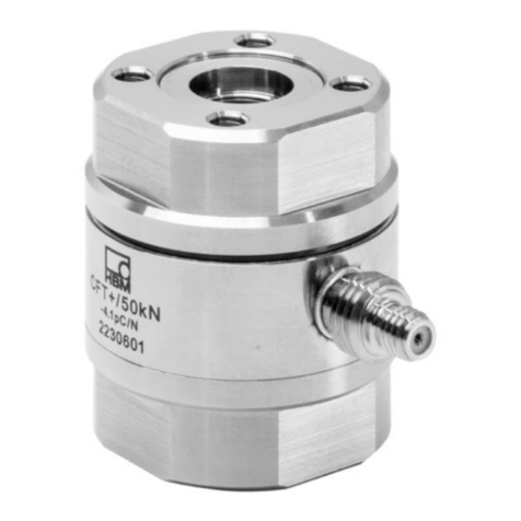
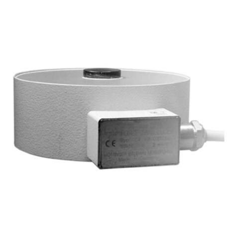
HBM P8AP User manual

Operating Manual | Bedienungsanleitung |
Manuel d'emploi | Istruzioni per l'uso |
Manual de empleo
English Deutsch Francais Italiano Español
P8AP

Hottinger Baldwin Messtechnik GmbH
Im Tiefen See 45
D-64239 Darmstadt
Tel. +49 6151 803-0
Fax +49 6151 803-9100
Email: [email protected]
Internet: www.hbm.com
Mat.: 7-2001.2079
DVS: A2079-4.0
11.2014
E Hottinger Baldwin Messtechnik GmbH.
Subject to modifications.
All product descriptions are for general information only.
They are not to be understood as a guarantee of quality or
durability.
Änderungen vorbehalten.
Alle Angaben beschreiben unsere Produkte in allgemeiner
Form. Sie stellen keine Beschaffenheits- oder Haltbarkeits-
garantie im Sinne des §443 BGB dar.
Sous réserve de modifications.
Les caractéristiques indiquées ne décrivent nos produits
que sous une forme générale. Elles n'impliquent aucune
garantie de qualité ou de durablilité.
Con riserva di modifica.
Tutti i dati descrivono i nostri prodotti in forma generica e non
implicano alcuna garanzia di qualità o di durata dei prodotti
stessi.
Reservado el derecho a modificaciones.
Todos los datos describen nuestros productos de manera
general. No representan ninguna garantía de calidad o de
durabilidad.

Operating Manual | Bedienungsanleitung |
Manuel d'emploi | Istruzioni per l'uso |
Manual de empleo
English Deutsch Francais Italiano Español
P8AP
Absolute pressure transducer

2 A2079-4.0 P8AP
English
1 Safety Instructions 3........................................
2 Markings Used 7...........................................
2.1 Symbols on the transducer 7..................................
2.2 The marking used in this document 7...........................
3 Scope of Supply 8..........................................
4 Field of Application 8.......................................
5 Mechanical Construction 9..................................
5.1 Important precautions during installation 9......................
5.2 Mounting 10..................................................
5.3 Pressure peak damping option 10...............................
6 Electrical Connection 12.....................................
6.1 Connection in a six-wire configuration 12.........................
6.2 Connection in a four-wire configuration 12........................
6.3 Shortening the cable 13.......................................
6.4 Extending the cable 13........................................
6.5 EMC protection 14............................................
7 Maintenance 16..............................................
8 Waste Disposal and Environmental Protection 16..............
9 Specifications (per DIN 16086) 17.............................
10 Options 20..................................................
11 Dimensions 22..............................................

Safety Instructions
P8AP A2079-4.0 3
1 Safety Instructions
Designated use
The transducer is to be used exclusively for weighing
tasks and directly related control tasks within the load
limits detailed in the specifications for the respective
maximum capacities. Use for any purpose other than the
above is deemed to be non-designated use.
Any person instructed to carry out installation, commis-
sioning or operation of the device must have read and
understood the Operating Manual and in particular the
technical safety instructions.
In the interests of safety, the transducer should only be
operated by qualified personnel and as described in the
Operating Manual. It is also essential to comply with the
legal and safety requirements for the application con-
cerned during use. The same applies to the use of ac-
cessories.
The transducer is not intended for use as a safety com-
ponent. Please also refer to the "Additional safety pre-
cautions" section. Proper and safe operation requires
proper transportation, correct storage, siting and mount-
ing, and careful operation.
Operating conditions
SThe transducer must not be modified from the design
or safety engineering point of view except with our
express agreement. In particular, any repair or solder-
ing work on motherboards (exchanging components)
is prohibited.
SThe data in the technical data sheets must be com-
plied with when using the transducer. The respective
specified maximum loads in particular must never be

Safety Instructions
4 A2079-4.0 P8AP
exceeded. The following are set out in the technical
data sheets and must not be exceeded:
- Limit loads
- Permissible dynamic loads
- Temperature limits
SThe transducer is maintenance-free.
SA functional measuring chain is only created when the
(passive) transducer is connected to an amplifier. En-
sure that electromagnetic compatibility or integration
in a suitable EMC shielding design is provided. To do
this:
- Connect the cable shield extensively to the input of
the amplifier.
- Connect the measuring body, i.e. the housing, to
the ground.
Important
The transducer cable shield is not connected with the
housing (ground).
Qualified personnel
Qualified persons means persons entrusted with the in-
stallation, fitting, commissioning and operation of the
product who possess the appropriate qualifications for
their function.
This includes people who meet at least one of the three
following requirements:
SKnowledge of the safety concepts of measurement
and automation technology is a requirement and as

Safety Instructions
P8AP A2079-4.0 5
project personnel, they must be familiar with these
concepts.
SAs measurement or automation plant operating per-
sonnel, they have been instructed how to handle the
machinery. They are familiar with the operation of the
equipment and technologies described in this docu-
mentation.
SAs commissioning engineers or service engineers,
they have successfully completed the training to qual-
ify them to repair the automation systems. They are
also authorized to activate, ground and label circuits
and equipment in accordance with safety engineering
standards.
Working safely
SError messages should only be acknowledged once
the cause of the error is removed and no further
danger exists.
SAutomation equipment and devices must be designed
in such a way that adequate protection or locking
against unintentional actuation is provided (e.g. ac-
cess checks, password protection, etc.).
SAfter making settings and carrying out activities that
are password-protected, ensure that any controls that
may be connected remain in a safe condition until the
switching performance of the device has been tested.
Additional safety precautions
Additional safety precautions to meet the requirements of
the relevant national and local accident prevention regu-
lations must be taken in plants where malfunctions could
cause major damage, loss of data or even personal in-
jury.

Safety Instructions
6 A2079-4.0 P8AP
The scope of supply and performance of the transducer
covers only a small area of measurement technology.
Before starting up the device in a system, a project plan-
ning and risk analysis must first be implemented, taking
into account all the safety aspects of measurement and
automation technology so that residual dangers are min-
imized. This particularly concerns personal and machine
protection. In the event of a fault, the relevant precau-
tions must establish safe operating conditions.
General dangers of failing to follow the safety
instructions
The transducer corresponds to the state of the art and is
reliable. The transducer may give rise to residual dangers
if it is inappropriately installed or operated.

Markings Used
P8AP A2079-4.0 7
2 Markings Used
2.1 Symbols on the transducer
CE mark
The CE mark enables the manufacturer to guarantee that
the product complies with the requirements of the relev-
ant EC directives (the Declaration of Conformity can be
found on the HBM website (www.hbm.com) under HBM-
doc).
2.2 The marking used in this document
Important instructions for your safety are specifically
identified. It is essential to follow these instructions in or-
der to prevent accidents and damage to property.
Symbol Significance
WARNING This marking warns of a potentially dangerous situ-
ation in which failure to comply with safety require-
ments can result in death or serious physical injury.
Important
This marking draws your attention to important in-
formation about the product or about handling the
product.
Emphasis
See …
Italics are used to emphasize and highlight text and
identify references to sections, diagrams, or external
documents and files.

Scope of Supply
8 A2079-4.0 P8AP
3 Scope of Supply
1 P8AP absolute pressure transducer
1 Operating Manual
4 Field of Application
Absolute pressure transducers of the P8AP type series
are suitable for measuring static and dynamic liquid and
gas pressures. They are available for the measuring
ranges 0 … 10, 0 … 20, 0 … 50, 0 … 100, 0 … 200 and
0 … 500 bar. Whatever the mounting position, these
small and handy transducers can be used even when
space is tight.

Mechanical Construction
P8AP A2079-4.0 9
5 Mechanical Construction
5.1 Important precautions during
installation
SHandle the transducer with care.
SMake sure that the transducer cannot be overloaded.
WARNING
There is a danger of the transducer breaking or being
torn from its mounting if it is overloaded. This can cause
danger for the operating personnel of the system in
which the transducer is installed.
Implement appropriate safety measures to avoid over-
loads or to protect against the resulting dangers.
In the standard version, P8AP pressure transducers are
equipped with a connector tube (∅10 mm). But several
other variants are also available to you (see Chapter 10,
Options).
With high mechanical loads caused by vibrations or oscil-
lations and with dynamic pressure measurements, we
recommend using clamping ring glands (standard ver-
sion), for safety reasons.
All commercial screwed connections with cutting rings,
and clamping ring glands can be combined with the
P8AP for installation. The principle of screwed connec-
tions with cutting rings is shown in Fig. 5.1, using a pro-
gressive screwed ring connection made by Ermeto Arma-
turen GmbH as an example.

Mechanical Construction
10 A2079-4.0 P8AP
Swivel nut before tightening Swivel nut after tightening
Tube of the P8AP
Fig. 5.1 Principle of a screwed connection with cutting ring
5.2 Mounting
The transducer can be installed in any position, as re-
quired. If the transducer is used to measure dynamic
pressure characteristics in liquids, install it with the pres-
sure connection pointing upward, so that it not possible
for an air cushion to build up in the measurement tube
that could, for example, heat up unacceptably as a result
of dynamic loads.
Push the swivel nut with seal onto the tube.
Insert the tube into the connection piece of the
screwed connection.
Tighten the swivel nut.
5.3 Pressure peak damping option
The pressure transducer may be damaged by applica-
tions with a dynamic overload. This is a particular prob-
lem in applications that are next to fast-closing valves or
close to hydraulic cylinders, where loading is spasmodic.

Mechanical Construction
P8AP A2079-4.0 11
The pressure peak damping option helps to reduce tran-
sient, high pressure peaks to a permissible degree,
without restricting the transducer's dynamic properties.
The diagram shows the pressure
characteristic at a hydraulic cylinder
after a powerful impact. The (top)
pressure characteristic shows
dynamic pressure peaks with the
double pressure amplitude of
excitation.
With pressure peak damping (lower
diagram), the dynamic peaks are
reduced, but the excitation pressure
characteristic is not invalidated.
Fig. 5.2 Impact of pressure peak damping
If pressure peaks are caused by fast-acting valves or
sudden loading, we recommended using a K-P8AP in
option 6, version 2, to ensure pressure peak damping.

Electrical Connection
12 A2079-4.0 P8AP
6 Electrical Connection
The following can be connected for measurement signal
conditioning:
Scarrier-frequency amplifiers
SDC amplifiers
designed for SG measurement systems.
The P8AP transducer is delivered with a 5m long cable
with free ends, in a six-wire configuration.
6.1 Connection in a six-wire configuration
- bk
+ bu
+ wh
- rd
P
U
Connection cable with free ends, 5 m long
Bridge excitation
voltage UB
Output
voltage UA
Cable shield
Housing
bare
Sense lead
Sense lead
- gy
+ gn
Fig. 6.1 Pin assignment
6.2 Connection in a four-wire
configuration
When transducers in a six-wire configuration are connec-
ted to amplifiers in a four-wire configuration, the sense

Electrical Connection
P8AP A2079-4.0 13
leads of the transducers must be connected to the cor-
responding excitation voltage leads: Marking (+) with (+)
and marking (-) with (-), see Fig. 6.1. This measure also
reduces the cable resistance of the excitation voltage
leads. However, there will be a voltage loss on the supply
leads due to the cable resistance that is still present and
not compensated for by the six-wire configuration. A
large part of this loss can be eliminated by a calibration,
however, the temperature-dependent part remains.
Important
The TCsvalue given for the transducer in the specifica
tions therefore does not apply for the cable and trans
ducer combination when connection is in a four-wire con
figuration, where the cable percentage must be added.
6.3 Shortening the cable
If the transducer is connected to an amplifier in a six-wire
configuration, the transducer cable can be shortened as
required, without adversely affecting the measurement
accuracy.
6.4 Extending the cable
Only use shielded, low-capacitance measurement cables
for extension. Ensure that connection is perfect, with a
low contact resistance.
The cable of a six-wire transducer can be extended with
a cable of the same type.

Electrical Connection
14 A2079-4.0 P8AP
6.5 EMC protection
Background information
Electrical and magnetic fields often induce interference
voltages in the measuring circuit. But for reliable meas-
urements, signal differences of less than 1 μV must be
transmitted from the transducer to the evaluation elec-
tronics without interference.
Planning the shielding design
Due to the numerous application options and the different
local constraints, we can only provide you with informa-
tion for correct connection. The shielding design suitable
for your application must be planned locally by an appro-
priate specialist.
HBM load cells with shielded, round cables are EMC-
tested in accordance with EC directives and identified by
the CE mark.
Points to be observed
SUse shielded, low-capacitance measurement cables
only (HBM cables fulfill both conditions).
SDo not route the measurement cables parallel to
power lines and control circuits. If this is not possible,
protect the measurement cable with e.g. steel con-
duit.
SAvoid stray fields from transformers, motors and con-
tact switches.
SConnect the shield of the connection cable extens
ively on the shielding electronics housing.
SThe shield of the connection cable must not be used
for discharging potential differences within the system.

Electrical Connection
P8AP A2079-4.0 15
You must therefore lay sufficiently dimensioned po-
tential equalization lines to compensate for possible
potential differences.
Important
Potential equalization is specified for applications in po
tentially explosive atmospheres.

Maintenance
16 A2079-4.0 P8AP
7 Maintenance
The transducer is maintenance-free.
8 Waste Disposal and Environmental Protection
As waste disposal regulations may differ from country to
country, we ask that you contact your supplier to determ-
ine what type of disposal or recycling is legally applicable
in your country.
Packaging
The original packaging of HBM devices is made from re-
cyclable material and can be sent for recycling. Store the
packaging for at least the duration of the warranty. In the
case of complaints, the torque flange must be returned in
the original packaging.
For ecological reasons, empty packaging should not be
returned to us.

Specifications
P8AP A2079-4.0 17
9 Specifications (per DIN 16086)
Type P8AP
Accuracy class 0.3
Characteristic mechanical quantities
Measuring span bar 10 20 50 100 200 500
Lower range value bar
(abs.)
0
Fundamental resonance fre
quency of the diaphragm
kHz 12 16 29 60 86 134
Damping ratio of the diaphragm 1 0.01
Operating range at 23 °C % 0...150
Overload limit at 23 °C % 175
Test pressure % 175
Destructive range % >200
During dynamic loading
permissible pressure % 100
permissible oscillation width
(per DIN 50 100)
% 70 70 85 95 95 60
Material for parts which come
into contact with the measure
ment medium
inner surface stainless steel 1.4542
pressure connection (tube) stainless steel 1.4301
Material of the outer surface stainless steel 1.4301, PPE
Dead volume with tube1),
without pressure connection
mm31110
410
1100
400
1090
390
1060
360
1100
400
1020
320
Control volume mm32 1.5 0.5 0.3

Specifications
18 A2079-4.0 P8AP
Type P8AP
Measuring span 500200100502010bar
Characteristic electrical quantities
Nominal (rated) sensitivity mV/V 2 ±2%
Input resistance Ω420 (+180/-120) 370
(+130/-70)
Output resistance Ω330 (+90/-30)
Nominal (rated) range of the ex
citation voltage (rms value)
V 0.5...5 0.5...12
Characteristic curve deviation
(start setting)
% 0.3
Repeatability per DIN 1319 %±0.1
Temperature coefficient of the
zero point, relative to the measur-
ing span, per 10 K, in the nominal
(rated) temperature range
% 0.3 0.2
Temperature coefficient of the
sensitivity (measuring span), relat-
ive to the actual value, per 10 K, in
the nominal (rated) temperature
range
%±0.3
1) With other pressure connections, see options, the dead volume and material details can be found
in Chapter 10, page 20.
Table of contents
Languages:
Other HBM Transducer manuals