Emtek R100 User manual
EMTEK, LLC - R100 USERS MANUAL / AUG2019.REV01
1
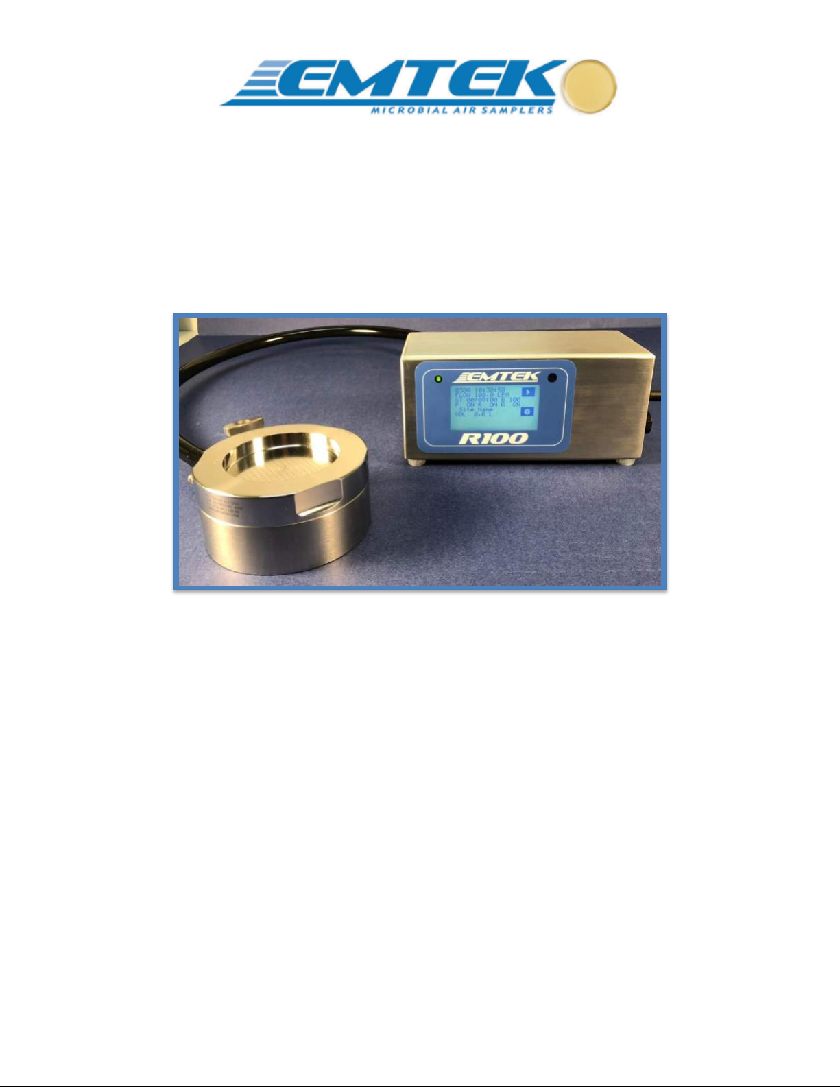
R100 Remote Microbial Air Sampler
User’s Manual
Contact Us for Customer Service and Technical Support
EMTEK, LLC
1500 Kansas Ave. Suite 4-C
Longmont, CO 80501
Website: http://www.emtekair.com
Phone: +1.877.850.4244 / +1.303.682.3168
Email: sales@emtekglobal.com
Fax: 303.223.2804

EMTEK, LLC - R100 USERS MANUAL / AUG2019.REV01
2
Table of Contents
Section 1 Specifications..........................................................................................................................................4
Section 2 General Information..............................................................................................................................5
2.1 Document Description..................................................................................................5
2.2 Copyright......................................................................................................................5
2.3 Disclaimer ....................................................................................................................5
2.4 License Restriction.......................................................................................................5
2.5 R100 Technical Description .........................................................................................6
2.6 Safety Notices...............................................................................................................8
2.6.1 Referenced Hazard Information .......................................................................8
2.6.2 Precautionary Labels.........................................................................................9
2.7 Standards and Regulation.............................................................................................11
2.7.1 21 CFR Part 11 Compliance...........................................................................11
2.8 Warranty.......................................................................................................................11
2.9 Calibration .....................................................................................................................11
Section 3 Product Introduction……………………………………………………………………………….…...12
3.1 Feature Summary .....................................................................................................122
3.2 Unpacking or Packing ..............................................................................................133
3.2.1 Component Checklist .....................................................................................13
3.2.2 Optional Accessories ......................................................................................15
3.2.3 Component Packaging....................................................................................16
3.2.3.1 Loading the Packaging for Calibration or Repair............................16
Section 4 Installation………….…………………………………………………..…………………………...…...17
4.1 Wiring Safety Information ...........................................................................................17
4.2 Electrostatic Discharge (ESD) Considerations...........................................................17
4.3 Electrical & Data Connections ...................................................................................19
Section 5 R100 Description..................................................................................................................................20
5.1 R100 Front View ........................................................................................................20
5.2 R100 Rear View .........................................................................................................21
Section 6 Quick Start Guide................................................................................................................................22
Section 7 Operating Instructions ........................................................................................................................23
7.1 Touch Screen Description and Function.....................................................................23
7.1.1 Setup Screen (Main Menu)............................................................................24
7.1.2 Run Display..........................................................................................……25
7.1.3 Set Sample Parameters .................................................................................26
7.1.4 Printer ...........................................................................................................28
7.1.5 Alarm (Flow) & IR Remote Settings.............................................................28

EMTEK, LLC - R100 USERS MANUAL / AUG2019.REV01
3
7.1.6 Delay, Test, & Hold Settings..........................................................................29
7.1.7 Site Descriptions ...........................................................................................30
7.1.8 Date & Time Settings.....................................................................................31
7.1.9 Data Output (Printer & USB).........................................................................32
7.1.10 Calibration (Due & Notification)..................................................................34
7.1.11 Administrative (Admin & User) ....................................................................35
7.1.11.1 Administrative Control Options ......................................................38
7.1.12 Unit Information (Firmware Version)............................................................40
7.1.13 Save (Sample) Programs (Select, Add, Delete) .............................................41
7.2 IR Remote Control .....................................................................................................43
7.2.1 Loading the Batteries into the Remote Control ...............................................43
7.2.2 Operating the R100 with the Remote Control.................................................44
7.3 Alarms/ Warning Screens ...........................................................................................45
7.4 Optional Thermal Printer Operation...........................................................................46
7.5 HEPA Filter Replacement...........................................................................................49
7.6 Touch Screen Sensor Calibration ...............................................................................50
Section 8 Network Operation of the R100..........................................................................................................51
Appendix A R100 Sampler - General Sampling Procedure..................................................................................52
A.1 R100 Operating Principles .........................................................................................52
A.2 Materials.....................................................................................................................53
A.3 Maintenance Inspection..............................................................................................53
A.4 R100 Sampler Assembly Set-Up and Testing.............................................................54
A.5 Storage and Transport.................................................................................................62
Appendix B Suggested R100 Sampler Sanitization.............................................................................................63
B.1 Materials.....................................................................................................................63
B.2 Sanitization Procedure................................................................................................64
Appendix C Optional Sampling Components......................................................................................................67
C.1 Horizontal Flow Inlet .................................................................................................67
C.2 Remote Exhaust Kit....................................................................................................68
Appendix D Suggested Sample Submission and Results Recording..................................................................69
Feller Calculation Tables………………………………………………………………...…...70
Appendix E Warranty............................................................................................................................................71
Appendix F Packaging ...........................................................................................................................................72

EMTEK, LLC - R100 USERS MANUAL / AUG2019.REV01
4
Section 1 Specifications
R100 Air Sampler Controller & Remote Air Sampler (RAS)
Motor Type
Blower Motor
Display/Interface
Two Color LCD with Touch Screen (Blue on White), CPU
Current Firmware Version
1.097 (or later versions, until otherwise revised)
Sample Time/Volume
Variable (User Defined), Maximums: 120-minutes/3396 Liters* @ 28.3 LPM, 30-min/3000L @ 100 LPM
Delay/Hold Times
Variable (User Defined)
Sample Flow Rates
28.3 or 100 liters per minute (LPM), or 1 cubic feet per minute (1 CFM)
NOTE: Requires separate inlet covers for the 28.3 (1 CFM) and 100 LPM Sample Rates
Flow Rate Control
Electronic, Closed-Loop, Mass-Flow Control
Test Media (Plates)
Size: 90mm Test Plates (Plastic Petri Dishes) / Fill Height: 15 to 40ml (standard to double, or high fill plates)
Printer (Optional)
Thermal Label or Paper
Control System (CPU)
Microprocessor Controlled (32bit PIC Processor)
Memory
512kb Flash Program , 128kb RAM Data, 1mb Sample Runs, 512kb EPROM Calibration Set Points
Unit Equipment ID/Number
User Defined/Selectable
Site Descriptions
User Created/Deleted/Selectable
Program Descriptions
User Created/Deleted/Selectable (Includes: Sample Rate, Volume/Time, Flow/Volume Units, Delay/Test/Hold)
Sample ID
Unique System Generated (Unit Serial # + 5 digit string)
Input/Output
USB Client 1.1, Ethernet 10BaseT-/100-BaseT
Audible Alarm
Internal (with User Volume Control)
Alarms
Flow Alarm +5% (On/Off)
Dimensions
LxWxH: 7.875x3.75x3.75 inches (200 x 95.25 x 95.25 mm)
R100 Enclosure Materials
Sanitary Inlet Connector: 316 Stainless Steel (SS) / Enclosure: Grained 316SS / Base Cover: Grained 316SS
RAS Inlet Cover Materials
6061 Aluminum, 28.3 LPM (1 CFM) Inlet Clear Anodized, 100 LPM Inlet Blue Anodized, 300 Holes/Inlet Cover
OR 316 Stainless Steel, 28.3 (1 CFM) LPM Inlet, 100 LPM Inlet, 300 Holes/Inlet Cover
RAS Remote Base Materials
6061 Aluminum, Clear Anodized Remote Base, Clear Anodized Test Plate Stage, Sanitary Tube Connector
OR 316 Stainless Steel, Remote Base, Test Plate Stage, Sanitary Tube Connector
Exhaust Filter
HEPA Filter, 0.2 micron, Replaceable
Weights (R100 & RAS)
R100 Controller : 3.75 lb (1.7 kg) / RAS Aluminum: 2.1 lb (~1 kg) / RAS 316SS: 6.25 lg (~2.8 kg)
AC/DC Power Supply
OPERATION REQUIRES AC POWER Input: 100-240 VAC, 50/60 Hz,130VA-168VA 1.4 AMPS / Output: DC 18V 3.6A
Operating Range
5-40º C, 10-80% RH, non-condensing*; Indoor Use; Max Altitude 6560 feet (2000 meters)
*Note: As temperature increases from 30 to 40º C, humidity range drops from 80 to 50% linearly.
Operational Tubing Length
Maximum Tubing Length at 28.3LPM Cannot Exceed 50 Feet (15 Meters) / 0.375” or 0.500” ID
Maximum Tubing Length at 100LPM Cannot Exceed 10 Feet (3 Meters) / 0.500” ID
Calibration
Flow Rate (28.3/1 CFM and/or 100 LPM)
Calibration Frequency
User Defined (Recommended every 6-12 months)
Verification
Sample Timer
Verification Frequency
User Defined (Recommended every 6-12 months)
Installation Category
Category 1
Pollution Degree
1 and 2

EMTEK, LLC - R100 USERS MANUAL / AUG2019.REV01
5
Section 2 General Information
2.1 Document Description
Document EMTEK.R100.001.rev01 (Second Edition). AUGUST 2019.
This document remains the official reference source for all revisions/releases of this product until rescinded by an
update, including current and updated versions of the operating firmware and software.
2.2 Copyright
© 2019 by EMTEK, LLC. All rights reserved.
2.3 Disclaimer
It is the policy of EMTEK, LLC to improve this manual and the products it describes as new technology,
components, software, and firmware become available. EMTEK, LLC reserves the right to make changes to any
products herein at any time without notice. In some instances, photographs and figures are of equipment prototypes.
Therefore, before using this document, consult your EMTEK, LLC representative for information that is applicable
and current. The information in this manual is believed to be accurate. However, EMTEK, LLC assumes no
responsibility for any inaccuracies that may be contained in this manual. In no event will EMTEK, LLC be liable
for direct, indirect, special, incidental, or consequential damages resulting from any defect or omission in this
manual, even if advised of the possibility of such damages. In the interest of continued product development,
EMTEK, LLC reserves the right to make improvements in this manual and the products it describes at any time,
without notice or obligation. No part of the contents of this manual may be reproduced or transmitted in any form
or by any means without the written permission of EMTEK, LLC.
2.4License Restriction
The purchase or use of an EMTEK, LLC product does not convey a license under any patent, copyright, trademark,
or other intellectual property right of EMTEK, LLC or third parties.

EMTEK, LLC - R100 USERS MANUAL / AUG2019.REV01
6
2.5R100 Technical Description
The R100 (EMTEK, LLC Remote 100) is a stationary, AC power operated, microbial air sampler. The unit utilizes its’ rear
sanitary inlet connector to connect to various lengths of tubing for remote sampling purposes, making it ideal for filling lines,
BFS, laminar flow hoods, biosafety cabinets, final filtration suites, etc. The unit is comprised of an enclosure and base cover
that are made of grained 316 stainless steel. The 316 stainless steel used to form the enclosure and base plate is ideal for any
testing environment as it will not shed particulates, will resist oxidation, and is impervious to various routinely used chemicals
and cleaning agents. The user interfaces with the R100 through a bicolor LCD touch screen for entering user defined sample
parameters and for the initiation and termination of sample runs. During operation the LCD displays key sample run
information, as well as a visual sample progress indicator.
The R100 is offered with two (2) sample flow rates (requires remote sampling head for operation): 28.3 LPM (1 CFM) and
100 LPM. The highest flow rate, 100 LPM, allows for the collection of a cubic meter of air in 10-minutes, while the 28.3
LPM (1 CFM) flow rate takes approximately 35 minutes to capture a cubic meter. At the 100LPM flow rate the R100 is capable
of sampling with a maximum tubing length of 10 feet (3 meters), while at the 28.3LPM flow rate the R100 is capable of
sampling with a maximum tubing length of 50 feet (15 meters). The flow is controlled through a proprietary CPU control
system, which offers automated flow control of the two defined flow rates. Flow rates are calibrated and set against traceable
standards using an external software program and may not be altered through the user interface on the unit. Sample rates and
total volume sampled maybe displayed and output in Cubic Feet, Liters, or Cubic Meters (only for total volume). Flow alarm
settings are available for the flow rates, which will produce both an audible and visual alarm during operation and may be
output to the optional printer upon completion/termination of the sample period. Alarm occurrences are maintained within
the systems internal memory with the associated sample parameter information until the 500-sample run memory buffer is
cleared.
The R100 operates in conjunction with the RAS with separate sieve impaction inlet covers for each of the two flow rates, 28.3
LPM (1 CFM) and 100 LPM. The RAS is sold in both Anodized Aluminum, and 316SS. The R100 Package can be ordered
with either option, and additional RAS samplers, or inlet covers may be ordered separately. The inlet covers include a 300-
hole pattern with appropriate inlet hole sizing for each flow rate to assure optimal physical and biological recovery capabilities.
Each inlet cover includes a distance gauge, which works in conjunction an adjustable media stage to assure an ideal distance is
maintained between the inlet cover and test media surface for appropriate microbial particulate capture. The air sampler uses
standard 90mm agar based microbial test plates (e.g., Trypticase Soy Agar (TSA)). During testing the sampled air volume
drawn through each air sampler is HEPA filtered before being exhausted within the R100.
The R100 software, allows for sampling periods of up to 120-minutes (or 120 Cubic Feet/3396 Liters/3.4 Cubic Meters) at the
28.3 LPM sample rate, while sample times are limited 30-minutes (or 106 Cubic Feet/3000 Liters/3 Cubic Meters) at 100 LPM.
While the stated time periods, or total sample volumes are allowed by the R100, EMTEK strongly suggests that all sampling
periods employed by be qualified by the user to verify appropriate organismal recovery. In addition, the R100 offers the user
the capability of entering an initial sample delay, as well as hold and test periods for each sample run. This initial sample
delay allows the user time to exit the immediate area of the sample location, while the hold and test period settings allows for
intermittent sampling of an area or process for an extended time period, as determine appropriate by the user. For an example,
the user may set an initial delay period of 3-minutes and then opt to sample for 5-minute periods with 5-minute hold periods
between each 5-minute sampling period, which will occur for a period up to the maximum total sampling period defined for
the flow rate chosen. If the flow rate chosen is 28.3 LPM, and the maximum active sampling period set is 60-minutes, this

EMTEK, LLC - R100 USERS MANUAL / AUG2019.REV01
7
would allow for twelve (12) 5-minute test periods, followed by eleven (11) 5-minute hold periods, for a total plate exposure
time of 118-minutes (including the 3-minute initial delay). This would result in a total of 60-minutes of active sampling. The
blower motor powers down during hold periods. Again, EMTEK recommends the user qualify any sampling plan used, to
include sample delay, and test/hold periods.
The R100 maintains key sample run parameter data within its internal memory, which is maintained until the memory buffer
is cleared by the user or unit administrator, and/or if the 500-sample run memory buffer capacity is exceeded. Based on
administrative options, the unit will either allow no more runs to be taken with the unit until the run data is reviewed and cleared,
or it will remove the oldest run stored with each new run take. The data maintained in the system includes set/actual flow
rate, set/actual sample volume, sample start/end times, set delay, test and hold period, equipment and serial numbers, calibration
date and due date of the controller/air sampler(s), user defined site description, user ID, and alarms during sampling. An
alphanumeric keypad is provided on the touch screen for entering user defined site identifiers/descriptions. All sample runs are
date and time stamped and are also assigned a unique sample identification string which is comprised of the units assigned
serial number and a non-repeating character string up to 99,999 samples. The run data cannot be altered within the CPU system
of the R100. It may only be output (via USB Stick, or Printer), viewed (via LCD, or PC), or cleared from the system.
Sample runs on the R100 can be initiated through either the R100 touch screen Run Display screen, the supplied Infrared
Remote (IR Remote), or by remote PC operation using our PC Control Software. Every R100 will come standard with
EMTEK’s proprietary PC Control Software from EMTEK’s P100 Product line, in addition to the unit’s MODBUS Mapping
Data. EMTEK’s PC Control Software will allow any technician to remotely control single, or multiple R100's via Ethernet
connection to a Local Area Network (LAN). The technician will be able to perform the following functions of the unit remotely
with this software: Start, Stop, Pause, Resume Set/View: Date, Time, Sample Volume, Sample Time, Delay, Test, Hold, Site
ID, Bldg/Room Data. In addition, the technician will be ale to view or output an on-screen .csv file, and will be able to print
these data through any printer connected to the same network. PDF output of the sample run data, is possible from the PC
Control software, if the PC has a PDF printing option.
Alternatively, the MODBUS Mapping will allow for integration into any internal facility monitoring systems with some effort
from an internal IT department. Using either the R100 display, IR Remote, or PC, the user can START, PAUSE, RESUME,
or STOP a sampling session. The IR Remote allows for these functions at up to a 40-Foot distance, or approximately 12
meters, with line of site to the R100 IR Receiver window located just above the touch screen display on the R100. The
supplied single IR remote can operate up to 5 R100’s with different IR ID#’s set on the unit (user selectable IR ID#’s 1 through
5).
There are several options available for the R100. This includes a portable thermal printer, horizontal flow inlet, remote
exhaust kit, and remote sampling kit. The thermal printer is battery operated and can utilize both paper and label stock
available from EMTEK. There are two options for the label stock. This includes labels that use black mark detection with
backing and a tear of perforation, or liner-less labels (no-backing self-sticking) without tear of perforations. The printer
outputs the defined key sample parameter data following each run (if desired). Additionally, the user can output duplicate
labels/data from sample data stored in the memory buffer based on a requested number of samples. The horizontal flow inlet
allows for testing in areas of horizontal air flow such as horizontal flow Laminar Air Flow Hoods/Benches. The remote
exhaust kit allows for attachment of tubing to exhaust sampled air away from, or outside of the location being sampled (e.g.,
Isolator, ISO 5 Filling Line, LAF Hood, etc.). The remote sampling kit allows for attachment of remote probe tubing to the
inlet of the RAS, for locations where the RAS may not fit, or for very critical locations where sample plate loading/unloading
in that location is not desirable
EMTEK, LLC - R100 USERS MANUAL / AUG2019.REV01
8
2.6 Safety Notice
Please read this entire manual before operating this equipment. Pay attention to all danger, warning and caution
statements. Failure to do so could result in serious injury to the operator or damage to the equipment. To make
sure that the protection provided by this equipment is not impaired, do not use or install this equipment in any
manner other than that specified in this manual.
English
DANGER: Electric Shock or Electrocution Hazards
1. Disconnect all power sources before servicing the R100
2. Do not disassemble the R100 controller to attempt any repairs.
3. Contact EMTEK, LLC or other qualified service personnel if the unit malfunctions.
4. Do not submerse the R100 controller or any sampler in any liquid.
Français
DANGER: un choc électrique ou des dangers d'électrocution
1. Débranchez toutes les sources d'alimentation avant d'intervenir sur le R100
2. Ne démontez pas le contrôleur R100 pour tenter une réparation.
3. Contacter EMTEK, LLC ou autres membres du personnel d'entretien qualifié en cas de
dysfonctionnement de l'appareil.
4. Ne pas plonger le contrôleur R100 ou échantillonneur dans un liquide.
2.6.1 Referenced hazard information
English
DANGER
Indicates a potentially or imminently hazardous situation which, if not avoided, will
result in death or serious injury.
Français
DANGER
Indique une situation potentiellement dangereuse ou imminent qui, si elle n'est pas évitée,
entraîner la mort ou des blessures graves.
English
WARNING
Indicates a potentially or imminently hazardous situation which, if not avoided,
could result in death or serious injury.
Français
AVERTISSEMENT
Indique une situation potentiellement dangereuse ou imminent qui, si elle n'est pas évitée,
pourrait entraîner la mort ou des blessures graves.

EMTEK, LLC - R100 USERS MANUAL / AUG2019.REV01
9
English
CAUTION
Indicates a potentially hazardous situation that may result in minor or moderate injury.
Français
ATTENTION
Indique une situation potentiellement dangereuse qui mai entraîner des blessures plus ou modérée
blessure.
Important Note: Indicates a situation which, if not avoided, may cause damage to the instrument. Information that requires
special emphasis.
Note Importante : Indique une situation qui, si non évité, peut provoquer le dommage à le instrument. Les informations qui
exigent l'accentuation spéciale.
Note: Information that supplements points in the main text.
2.6.2 Precautionary labels
Read all labels and tags attached to the instrument. Personal injury or damage to the instrument could occur if not
observed.
English
Electrical equipment marked with this symbol may not be disposed of in European public disposal
systems after 12 August of 2005. In conformity with European local and national regulations (EU
Directive 2002/96/EC), European electrical equipment users must now return old or end-of life
equipment to the Producer for disposal at no charge to the user.
Note: For return for recycling, please contact the equipment producer or supplier for instructions on
how to return end-of-life equipment, producer-supplied electrical accessories, and all auxiliary items
for proper disposal.
Français
Les équipements électriques marqués de ce symbole mai ne pas être éliminés dans les systèmes européens
de disposition du public après le 12 août 2005. En conformité avec les réglementations locales
européennes et nationales (Directive européenne 2002/96/CE), les utilisateurs européens
d'équipements électriques doivent maintenant retourner vieux ou en fin de vie des équipements au
producteur pour l'élimination, sans frais pour l'utilisateur.
Remarque: Pour le retour pour recyclage, s'il vous plaît contacter le producteur ou le fournisseur du
matériel pour obtenir des instructions sur la façon de revenir en fin de vie des équipements,
producteurs-fournis accessoires électriques, et tous les éléments auxiliaires pour une élimination
appropriée.
EMTEK, LLC - R100 USERS MANUAL / AUG2019.REV01
10
English
This is the safety alert symbol. Obey all safety messages that follow this symbol to avoid potential
injury. If on the instrument, refer to the instruction manual for operating on or safety information.
Français
Ceci est le symbole de sécurité. Respectez tous les messages de sécurité qui suivent ce symbole afin
d'éviter d'éventuelles blessures. Si sur l'instrument, se reporter au manuel d'instructions pour
l'exploitation ou de l'information sur la sécurité.
English
This symbol indicated the presence of devices sensitive to Electro-static Discharge (ESD) and
indicated that care must be taken to prevent damage with the equipment.
Français
Ce symbole indique la présence de dispositifs sensibles à Electro-Static Discharge (ESD) et a
indiqué que les soins doivent être prises pour prévenir les dommages aux équipements.
English
This symbol indicates that a risk of electrical shock and/or electrocution exists.
Français
Ce symbole signifie qu'il existe un risque de choc électrique et/ou d'électrocution existe.

EMTEK, LLC - R100 USERS MANUAL / AUG2019.REV01
11
2.7 Standards and Regulation
2.7.1 21 CFR Part 11 Compliance
Sample Parameter Information and Electronic Records
The R100 Central Processing Unit (CPU) stores sample parameter information for up to 500 sample runs in the
internal memory. This memory is not removable or alterable by the user. The sample parameter information
maintained in the system for each run includes: Serial#, Equipment#, Building/Room (if entered through PC
software), Start Date, Start time, End time, Average Flow, Total Volume, Total Run Time, Delay (duration), Hold
(duration), Sample (duration), User ID, Run ID (system generated), Site (ID), Hi Flow (duration), and Low Flow
(duration). The stored sample parameters can be cleared/deleted by the user (if allowed through Admin control), or
administrator, but cannot be edited. Further, sample parameter information of a specific sampling event cannot be
selectively deleted or altered by the user. The R100 can re-print sample parameter information using the optional
thermal printer. The user can select the number of previous samples to be printed.
The sample parameter information stored in the internal memory of the R100 controller can be either printed to the
optional thermal printer, output to a USB stick for further transfer, or transferred to an external computer through
an Ethernet connection and optional PC based software. The sample parameter information can be deleted but
cannot be altered while residing within the internal memory of the R100 CPU. This sample parameter information
may be exported from the internal memory. EMTEK, LLC does not provide software utilities to comply with the
requirements of 21 CFR Part 11 after the data is transferred from a R100 controller to an external source. Users that
are subject to FDA regulations are responsible for maintaining compliance with 21 CFR Part 11 after the data is
transferred from the R100 to an external source.
2.8 Warranty
EMTEK, LLC provides a 2-Year Limited Warranty- See Appendix E
2.9 Calibration
EMTEK and your local area distributor offer calibration services and other options for your R100 Microbial Air
Samplers. A 6 or 12 month (annual) calibration cycle is recommended. Contact EMTEK or your distributor for
calibration questions, service, or options.

EMTEK, LLC - R100 USERS MANUAL / AUG2019.REV01
12
Section 3 Product Introduction
The R100 is a state-of-the-art Microbial Air Sampler controller for use with the EMTEK, LLC line of microbial
sampling devices. It uses mass flow control to accurately regulate the selected air-flow for precise measurement of
the collected volume.
3.1 Feature Summary
Touch Screen Interface
User-friendly touch screen for intuitive operation.
Storage Functions
Internal memory for the storage of user sample sites, sample runs, sampling programs, calibration points,
user and administrative ID’s and passwords.
Thermal Printer:
An optional thermal paper/label printer can output the captured sample parameter information such as
the site description, unit identification, set flow rate, actual flow rate, sample volume collected, user ID,
and high/low flow alarms.
Network/Input Functions:
Supports calibration programming, remote PC based operation, data transfer, and firmware updates
•Ethernet Port:
oRemote Data Printer
oRemote PC based unit control, data viewing/output via optional PC based software
oUnit Calibration via PC based calibration software
•USB Port:
oFirmware Updates
oData Transfer to USB Stick
IR Remote Control:
•Supports Start / Stop of the sample period
•Supports Pause / Resume of the sample period
•Operates up to five (5) R100 Units
EMTEK, LLC - R100 USERS MANUAL / AUG2019.REV01
13
3.2 Unpacking or Packing the R100 & Components
Remove all items from the carrying case, and/or other shipping container and inspect them for damage. Make sure
that all the items listed are included (Fig 3.2.1), dependent upon purchase options. If any of the items not marked
(optional) are missing or damaged, contact your distributor, or EMTEK (sales@emtekglobal.com).
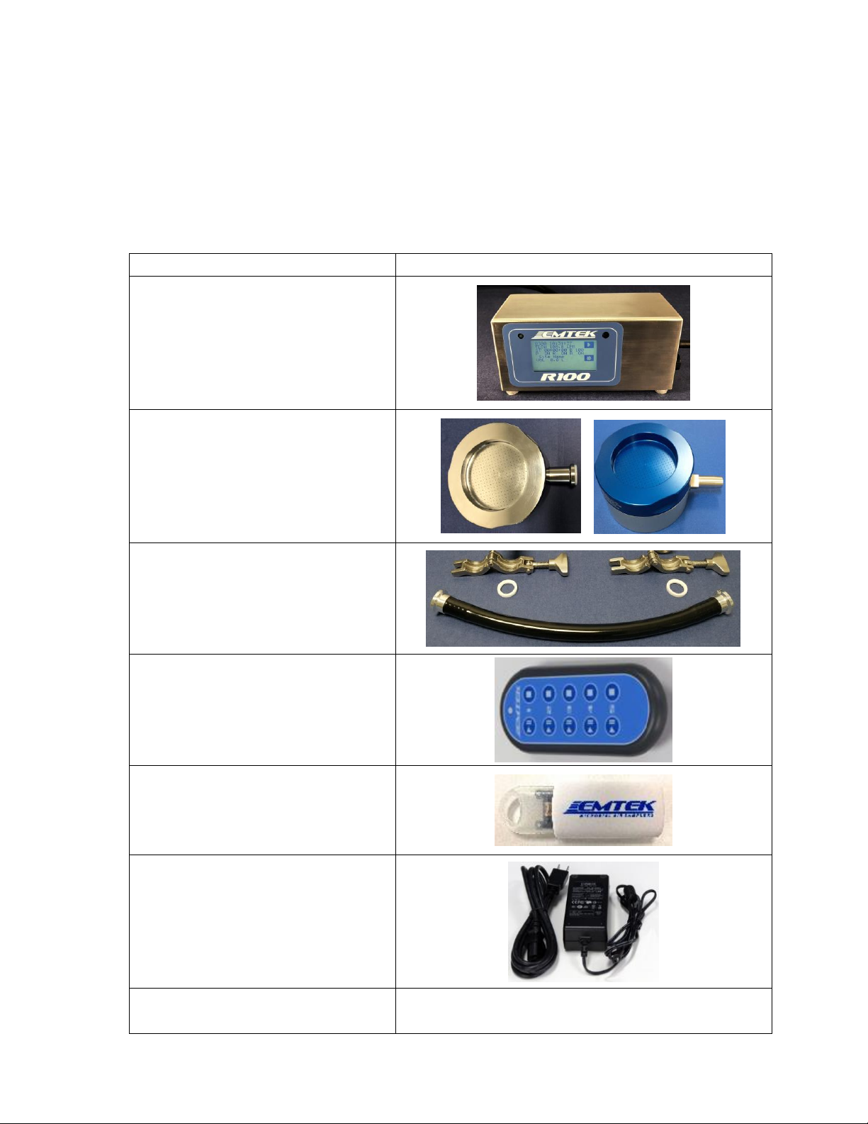
3.2.1 Instrument Component Checklist –Standard R100 Package Components
Item# & Description (Quantity)
Image
1
R100 Remote Microbial Air Sampler
(1)
2
Remote Air Sampling (RAS) Base
Assembly and Inlet Cover
(1-of material and flow rate ordered)
See page #15 for RAS Vacuum
Connector Configuration Notes
3
10 Feet (3 Meters) of 0.500”ID
Tubing (1),
Sanitary Clamps(2), Seals (2), Sanitary
Tube Fittings (2)
4
Infrared Remote (IR) Control (1)
5
USB Stick-8 GB (Contains Users
Manual, other applicable Documents,
and PC Control Software) (1)
6
Power Supply (AC/DC Power
Block/AC with Applicable Adapter
Cord Depending on Region) (1)
7
NIST Traceable Calibration Report (1)
NOT SHOWN

EMTEK, LLC - R100 USERS MANUAL / AUG2019.REV01
14
RAS VACUUM CONNECTOR FITTING CONFIGURATION OPTIONS
The RAS includes two options for location of the vacuum connector fitting, as follows:
OPTION I: Option one is the more standard side port connect, more commonly used with flexible
tubing.
OPTION II: Option two is to use the connection port on the bottom of the RAS. This allows for
hard mounting of the RAS using the sanitary fitting and clamp, to clamp it to rigid
piping with a sanitary connector end.
PORT PLUG: The supplied threaded plug shown is included with the RAS, and can be removed and
used as desired to plug the unused connector port (Plug shown in bottom connector
port).

EMTEK, LLC - R100 USERS MANUAL / AUG2019.REV01
15
3.2.2 Optional Components
Fig. #
Item Description
1
Extra Inlet Cover(s) (28.3 or
100 LPM, Aluminum or
Stainless Steel)
2
Portable Printer Kit:
Portable Printer (1), Power
Adapter (1), Ethernet to
RJ11 Adapter Cord (1),
Label Rolls (3)
3
Horizontal Flow Inlet
(w/3 O-Rings)
4
Remote Exhaust Kit
(w/5 Feet of Tubing)
5
Additional RAS Sampler
6
Remote Sampling Adpater
(Comes with or w/o tubing)
7
Inlet Cover Lid
NOTE: See Appendix C for description/use of R100 Optional Components

EMTEK, LLC - R100 USERS MANUAL / AUG2019.REV01
16
3.2.3 Component Packaging
General Description
The R100 comes packaged in an a custom foam box insert (Fig. 1). The foam has custom cut outs for
the included components, R100 Controller, RAS, as well as some additional accessories, which will
safely hold for transport, and shipping. If numerous optional accessories are ordered, the additional
components may be delivered in an oversized box, along with the R100 Package, or a separate extra
box, if they do not all fit in one package. See Appendix F for full packaging details.
R100 Controller and RAS Sampler Component Tray and Spacer Loading
Fig. 1 - R100 Component Tray
R100 Controller
RAS
PWR & Supply/AC Cord
Extra
(RAS, Inlet
Cover, etc.)
Sanitary Clamps
Connectors
IR Remote
USB Drive
Extra
(RAS, Inlet
Cover, etc.)

EMTEK, LLC - R100 USERS MANUAL / AUG2019.REV01
17
Section 4 Installation
English
Danger
Only qualified personnel should perform the tasks specified in this section.
Français
Danger
Le personnel seulement qualifié devrait exécuter les tâches spécifiées dans cette section.
4.1 Wiring safety information
Follow all warnings and notes when making wiring connections to the instrument (Safety information on page 8).
English
DANGER
Electric shock hazard. Always disconnect power to the instrument when making electrical
connections.
Français
DANGER
Un choc électrique risque. Toujours couper l'alimentation de l'instrument lors des branchements
électriques.
4.2 Electrostatic discharge (ESD) considerations
Important Note: To minimize hazards and ESD risks, maintenance procedures not
requiring power to the R100 should be performed with power removed.
Delicate internal electronic components can be damaged by static electricity,
resulting in degraded instrument performance or eventual failure.
Note Importante: Pour minimiser les dangers et les risques de l'EDD, les procédures d'entretien
non nécessitant une alimentation à la R100 devrait être exécuté avec la
puissance retirés. Interne sensible composants électroniques, peuvent être
endommagés par l'électricité statique, résultant en instrument une
dégradation des performances ou de l'échec éventuel.

EMTEK, LLC - R100 USERS MANUAL / AUG2019.REV01
18
The manufacturer recommends taking the following steps to prevent ESD damage to
your instrument:
• Before touching any instrument electronic components (such as printed circuit cards
and the components on them) discharge static electricity from the body. To discharge
static electricity, touch an earth-grounded metal surface such as the chassis of an
instrument, or a metal conduit or pipe.
• To reduce static build-up, avoid excessive movement. Transport static-sensitive
components in anti-static containers or packaging.
• To discharge static electricity from the body and keep it discharged, wear a wrist
strap connected by a wire to earth ground.
• Handle all static-sensitive components in a static-safe area. If possible, use
anti-static floor pads and work bench pads.

EMTEK, LLC - R100 USERS MANUAL / AUG2019.REV01
19
4.3 Electrical/Data Connections
English
DANGER
Electric shock hazard. Always disconnect power to the instrument when making electrical
connections.
Français
DANGER
Un choc électrique risque. Toujours couper l'alimentation de l'instrument lors des branchements
électriques.
Fig 4.3.1
R100 Side View
Connections:
1. DC Input Port: AC/DC Power Supply (Power Connected Operation)
2. USB Port: Data Output to USB stick, firmware updates
3. Ethernet Port: Calibration, Optional Printer Connection, Remote PC Operations
4. Power On/Off Button
1
2
3
4
EMTEK, LLC - R100 USERS MANUAL / AUG2019.REV01
20
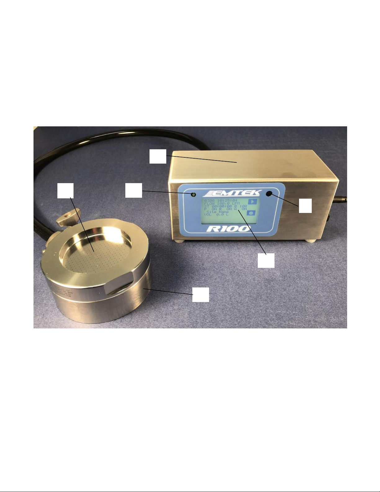
Section 5 R100 Description
5.1 R100 Front View
Fig 5.1.1
R100 Front/Side View
1. RAS Inlet Cover (100 LPM in 316SS Shown)
2. RAS Remote Base (316SS Shown)
3. Unit Power ON Indicator Green LED (Power On=Solid, Sample Run=Flashing)
4. IR Remote Receiving Sensor
5. LCD/ Touchscreen Interface
6. 316 Stainless Steel Enclosure
5
2
1
3
4
6
Table of contents
Popular Laboratory Equipment manuals by other brands

AAG
AAG Solo user manual

Kambic
Kambic OBM-LT user manual

Thermo Scientific
Thermo Scientific Harris MBF-700 Installation and operation manual

Agilent Technologies
Agilent Technologies 4150 TapeStation system System manual

Heathrow Scientific
Heathrow Scientific Sprout Plus instruction manual

Omni International
Omni International Omni Mixer owner's manual


