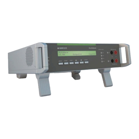
EMTEST EFT 500 User manual

ELECTROMAGNETIC
COMPATIBILITY
CONSULTING
AND
SIMULATION
Version
Replaces
Filename
Printdate
(
5
?
EM
TEST
BURST
GENERATOR
Type
EFT
500
MANUAL
1.00
/
24.11
.
97
no
previous
version
EFTBA
-
A
5
.
DOC
8.02
.
01

SPECIFIC
PRECAUTIONS
<
3
EM
TEST
Observe
all
of
these
precautions
to
ensure
your
personal
safety
and
to
prevent
damage
to
the
test
equipment
of
our
product
range
.
The
generators
correspond
to
installation
category
(
overvoltage
category
)
II
.
Power
Source
The
equipment
is
intended
to
operate
from
a
power
source
that
will
not
apply
more
than
250
VRMS
between
the
supply
conductors
or
between
either
supply
conductor
and
ground
.
A
protective
ground
connection
,
through
the
grounding
conductor
in
the
power
cord
,
is
essential
for
safe
system
operation
.
Grounding
the
generators
The
generators
are
grounded
through
the
power
cord
.
To
avoid
electric
shock
,
plug
the
power
cord
into
a
properly
wired
receptacle
where
earth
ground
has
been
verified
by
a
qualified
service
person
.
Do
this
before
making
connections
to
the
input
or
output
terminals
of
the
test
equipment
.
Without
the
protective
ground
connection
,
all
parts
of
generators
are
potential
shock
hazards
.
This
includes
knobs
and
controls
that
may
appear
to
be
insulators
.
Use
the
Proper
Power
Cord
Use
only
the
power
cord
and
connector
specified
for
you
product
.
Use
only
a
power
cord
that
is
in
good
condition
.
Use
the
Proper
Fuse
To
avoid
fire
hazard
,
use
only
the
fuse
specified
in
the
parts
list
for
your
product
,
matched
by
type
,
voltage
rating
and
current
rating
.
Do
Not
Remove
Covers
or
Panels
To
avoid
personal
injury
,
do
not
operate
the
generators
without
the
panels
or
covers
.

Do
Not
Operate
in
Explosive
Atmospheres
The
generators
provides
no
explosion
protection
from
statistic
discharges
or
arcing
components
.
Do
not
operate
them
in
an
atmosphere
of
explosive
gases
.
Electric
Overload
Never
apply
generators
voltage
to
a
connector
which
is
not
specified
for
that
voltage
range
.
Read
carefully
the
following
operation
manual
!!
!
!
,
•

Recommended
Security
Aspects
The
Generators
correspond
to
equipment
of
security
class
I
.
Prior
to
Turning
on
the
Equipment
-
Before
putting
the
instrument
into
operation
please
check
the
equipment
you
have
received
for
damage
due
to
transportation
.
Check
the
single
boxes
as
well
as
the
generator
itself
for
mechanical
damage
.
Please
inform
the
manufacturer
before
switching
the
unit
on
.
Damage
due
to
transportation
-
Prior
to
turning
on
the
equipment
check
if
the
selected
supply
voltage
corresponds
with
the
mains
.
115
V
/
230
V
?
?
-
Equipment
of
security
class
I
which
is
powered
by
an
autotransformer
may
be
considered
as
follows
:
-
if
the
equipment
is
powered
by
an
auto
transformer
connected
to
a
mains
of
higher
voltage
,
be
sure
that
the
low
end
of
the
autotransformer
is
connected
with
the
neutral
of
the
mains
;
-
equipment
of
security
class
I
with
removable
neutral
or
with
mains
plug
:
It
is
only
permitted
to
insert
the
power
plug
in
a
mains
socket
with
protective
earth
lead
.
It
is
not
allowed
to
interrupt
or
disconnect
the
protective
earth
connection
.
Performance
of
Measurements
-
Each
interruption
or
disconnection
of
the
protective
earth
connection
inside
or
outside
the
equipment
may
lead
to
a
dangerous
situation
.
Intentional
interruption
is
prohibited
.
-
Interconnections
between
such
equipments
or
to
others
,
e
.
g
.
remote
control
to
personal
computer
,
may
be
completed
with
original
cables
recommended
by
the
manufacturer
.
Maintenance
,
Adjustments
,
Exchange
of
Parts
-
When
removing
the
housing
cover
or
other
parts
of
the
equipment
,
parts
exposed
to
high
voltage
may
become
accessible
.
High
voltage
and
high
current
signify
danger
to
life
.

I
-
Do
not
perform
maintenance
or
service
work
until
you
have
disconnected
the
equipment
from
the
mains
.
Be
sure
the
capacitors
or
other
voltage
-
carrying
parts
are
discharged
.
-
If
maintenance
or
service
work
is
necessary
,
it
must
be
performed
only
by
experts
who
are
familiar
with
the
existing
danger
.
-
It
has
to
be
assured
that
only
fuses
of
recommended
type
and
nominal
current
are
used
for
replacement
.
It
is
not
allowed
to
use
repaired
fuses
.
Failures
and
Overstressing
-
If
it
is
assumed
that
a
riskless
operating
mode
of
the
equipment
is
no
longer
possible
,
the
mains
connection
must
be
removed
and
the
equipment
secured
from
unintentional
use
.
-
It
may
be
assumed
that
an
endanger
operating
is
given
:
-
when
the
equipment
shows
recognisable
damages
;
-
when
the
equipment
is
not
working
;
-
after
severe
transportation
stress
;
-
after
longer
stock
-
keeping
under
disadvantageous
conditions
.
It
is
suggested
that
you
read
the
operating
manual
carefully
and
completely
.
It
is
absolutely
necessary
to
observe
and
comply
with
the
security
indications
.
Maintenance
The
generator
is
absolutely
maintenance
-
free
by
using
a
solid
state
semiconductor
switch
to
generate
the
test
events
.
Coupling
network
-
Due
to
the
various
national
safety
instructions
the
coupling
network
has
no
ON
/
OFF
key
as
well
as
no
internal
fuse
protection
.
The
EUT
must
be
fused
by
the
user
.
-
Special
supply
adapters
with
switch
and
fuse
protection
are
available
but
must
be
specified
by
the
user
.
-
Special
supply
cables
are
included
as
basic
equipment
.

Test
set
-
up
!
!
Attention
Immunity
Tests
!
!
Burst
test
is
an
immunity
test
on
electronic
equipment
.
Therefore
it
is
the
responsibility
of
the
user
to
avoid
critical
failures
and
risks
to
the
environment
and
operator
.
Long
and
distributed
lines
of
the
EUT
are
able
to
radiate
a
certain
energy
to
their
vicinity
.
Therefore
it
is
also
the
responsibility
of
the
user
to
decide
whether
it
is
allowed
to
conduct
immunity
tests
in
a
given
installation
.
Test
voltages
above
500
V
may
generate
spark
discharges
.
Therefore
it
is
forbidden
to
test
in
an
explosive
environment
.
National
and
international
recommendations
regarding
human
safety
must
be
followed
.
Handicapped
people
,
e
.
g
.
with
a
heart
defibrillator
,
should
be
excluded
from
testing
.

CONTENTS
1
.
Application
9
1.1
.
Introduction
9
1.2
.
Definitions
10
1.3
.
Sources
of
interference
11
2
.
Operating
Functions
...
13
2.1
.
Front
view
13
2.2
.
Rear
view
15
3
.
Operation
17
3.1
.
Description
of
the
menus
17
3.2
.
Quick
Start
19
3.3
.
User
test
routines
21
3.4
.
Test
routine
as
per
to
IEC
1000
-
4
-
4
.
..
.
26
3.5
.
Service
27
3.6
.
Set
-
up
28
4
.
Putting
into
Operation
.
29
4.1
.
Security
Aspects
,
.
29
4.2
.
Immunity
Tests
Burst
,
using
PC
’
s
29
4.3
.
Generator
function
check
32
5
.
Test
Equipment
EFT
500
34
5.1
.
Construction
34
5.2
.
Control
unit
35
5.3
.
High
voltage
unit
.
..
35
5.4
.
Coupling
network
..
.
.
36
6
.
Technical
Data
39
6.1
.
Pulse
forming
unit
39
6.2
.
Trigger
39
6.3
.
Burst
impulses
39
6.4
.
Output
39
6.5
.
Test
routines
40
6.6
.
General
data
40
7
.
Maintenance
.
41
7.1
.
General
41
7.2
.
Limiting
values
41
7.3
.
Coupling
network
41
8
.
Delivery
Groups
8.1
.
Basic
equipment
8.2
.
Accessories
and
options
9
.
Remote
Control
9.1
.
Interfaces
9.2
.
General
information
9.3
.
Parameter
of
the
remote
commands
9.4
.
E
commands
9.5
.
N
commands
SO
)
Ol
W
W
N
)
N
)
N

9.6
.
A
commands
47
9.7
.
Back
messages
..
48
10
.
Appendix
49
10.1
.
Declaration
of
CE
-
Conformity
49
10.2
.
Declaration
for
safety
requirements
49
10.3
.
List
of
sales
representatives
49
10.4
.
EFT
500
-
General
Diagram
49
10.5
.
EFT
500
-
Overview
49

1
.
Application
1.1
.
Introduction
With
more
complex
electronic
devices
and
systems
the
tendency
towards
lower
signal
levels
,
particularly
those
involving
microprocessors
,
has
increased
their
susceptibility
to
interference
,
as
the
ratio
between
wanted
and
unwanted
signals
becomes
increasingly
unfavourable
.
When
electronic
circuits
are
subjected
to
interference
,
their
performance
may
be
degraded
causing
malfunction
,
or
even
catastrophic
failure
.
The
most
common
factors
influencing
electronic
devices
may
be
described
as
follows
:
-
Compared
with
tube
-
equipped
instruments
having
mechanical
switches
,
modern
measuring
and
control
technology
incorporating
microprocessors
have
had
their
signal
and
measuring
levels
decreased
by
one
order
of
magnitude
,
while
frequencies
increased
by
a
factor
of
10
.
In
addition
,
present
process
automation
requirements
dictate
the
use
of
commercially
available
microprocessors
,
which
have
to
work
impeccably
-
often
online
-
under
these
hostile
environmental
conditions
.
The
end
is
not
yet
in
sight
:
newer
devices
will
soon
be
appearing
with
still
shrinking
geometry
and
escalating
sensitivity
.
-
Levels
of
interference
are
growing
due
to
new
technological
developments
.
-
More
and
more
plastic
material
is
being
used
for
case
designs
,
increasing
the
tendency
to
expose
vulnerable
electronics
to
interference
rich
environments
.
Further
developments
in
microelectronic
circuits
will
bring
about
a
marked
reduction
in
the
interference
thresholds
.
That
is
the
reason
why
greater
attention
must
be
drawn
towards
the
EMC
behaviour
of
individual
components
and
electronic
systems
.
National
and
international
standardisation
organisations
have
released
or
are
still
working
on
guidelines
and
recommendations
to
provide
engineering
with
a
greater
harmonisation
between
EMC
and
electronic
circuits
and
systems
.
9

1.2
.
Definitions
-
Electromagnetic
Compatibility
(
EMC
)
Ability
of
a
device
to
correctly
function
in
its
electromagnetic
environment
without
introducing
intolerable
disturbances
to
that
environment
or
to
other
equipment
.
-
Coupling
Interaction
between
circuits
,
transferring
energy
from
one
circuit
to
another
.
-
Electromagnetic
Interference
(
EMI
)
Electromagnetic
disturbance
which
manifests
itself
in
performance
degradation
,
malfunction
,
or
failure
of
electric
or
electronic
equipment
.
-
Immunity
Capability
of
a
device
,
equipment
or
system
to
be
unaffected
by
electromagnetic
disturbances
.
-
Surge
A
transient
wave
of
electric
current
,
voltage
or
power
in
the
circuit
lasting
from
a
few
nanoseconds
to
several
seconds
.
-
Sink
(
victim
)
An
electronic
equipment
which
causes
a
degradation
,
malfunction
,
or
failure
of
electric
or
electronic
equipment
.
-
Susceptibility
The
characteristic
of
electronic
equipment
to
procedure
an
undesirable
response
when
exposed
to
electromagnetic
energy
.
10

1.3
.
Sources
of
interference
Surges
result
from
the
redistribution
of
electromagnetic
energy
.
Such
redistributions
and
their
most
important
sources
are
listed
below
.
-
Stationary
and
non
-
stationary
transmitters
Both
stationary
high
power
radio
transmitters
and
non
-
stationary
walkie
-
talkies
operating
in
the
immediate
vicinity
of
systems
or
equipment
lead
to
uncontrolled
electromagnetic
irradiation
into
vulnerable
electronic
equipment
.
Parameters
:
narrow
-
band
,
continuous
electromagnetic
interference
(
modulated
)
.
-
Electrical
fast
transients
(
burst
)
Electromagnetic
influences
produced
in
the
neighbourhood
by
rapid
variation
of
voltage
and
current
as
a
result
of
the
abrupt
change
of
a
switch
from
a
non
-
conductive
to
a
fully
conductive
status
or
vice
versa
,
e
.
g
.
switching
inductive
loads
with
mechanically
moved
contacts
between
which
arcing
occurs
before
they
separate
.
Further
examples
are
provided
by
arc
-
overs
in
the
measuring
and
limiting
spark
gaps
used
in
high
voltage
test
facilities
.
Parameters
:
broad
-
band
pulse
interference
,
rise
time
of
pulses
of
a
few
nanoseconds
,
small
energy
content
and
high
repetition
rate
.
-
Atmospheric
discharges
,
lightning
and
switching
transients
Lightning
and
switching
transients
appearing
in
low
voltage
networks
of
industrial
installations
are
the
origin
of
pulse
-
cancelling
interferences
.
Parameters
:
range
of
voltage
some
tens
of
kV
,
range
of
current
some
tens
of
kA
,
high
-
energy
pulses
with
rise
times
in
the
microsecond
range
.
-
Breakdowns
,
power
failures
Fuse
blowing
as
the
result
of
a
short
-
circuit
may
affect
equipment
in
the
neighbourhood
in
the
following
way
:
a
)
power
failure
or
voltage
fluctuations
of
some
milliseconds
until
fuse
blows
.
b
)
whenever
there
is
an
abrupt
break
of
the
short
-
circuit
current
,
an
overvoltage
of
2
or
3
times
the
nominal
value
with
duration
up
to
1
ms
is
generated
.
11

-
Harmonic
frequency
disturbances
Generation
of
harmonics
takes
place
in
most
power
equipments
as
a
consequence
of
their
reactive
coupling
.
-
Electrostatic
discharge
Generation
of
an
electrostatic
charge
is
especially
favoured
by
the
combination
of
synthetic
fabrics
and
dry
atmosphere
.
There
is
a
big
variety
in
the
charging
process
.
A
common
situation
is
that
an
operator
walks
over
a
carpet
and
with
each
step
loses
electrons
from
his
body
to
the
fabric
.
Friction
between
the
operators
clothing
and
the
chair
can
also
produce
an
exchange
of
charges
.
The
operators
body
may
be
charged
either
directly
or
by
electrostatic
induction
;
in
the
latter
case
a
conducting
carpet
will
not
give
protection
unless
the
operator
is
adequately
earthed
to
it
.
The
effect
of
the
operator
discharge
may
be
a
simple
malfunction
of
the
equipment
or
damage
of
electronic
components
.
The
dominant
effects
can
be
attributed
to
the
discharge
current
(
<
100
A
)
and
voltage
(
<
30
kV
)
with
rise
times
in
the
nanosecond
range
.
12

2
.
Operating
Functions
2.1
.
Front
view
E
F T
500
EM
TEST
TESTSUPPLY
1
5
50
OHM
F
1
F
2
F
3
F
4
F
5
F
6
F
7
<
- -
>
.
00
EXIT
ESC
20
TESTON
G Q
0 7
CRO
.
8
®
Hh
-
@
L
11
(
§
)
©
—
II
—
(
p
)
N
©
—
II
—
(
§
j
)
PE
12
9
10
1
Display
2
’
’
Test
On
"
3
Function
keys
,
,
F
1
.
.
F
7
,
,
4
Cursor
keys
and
5
Knob
(
Inc
/
Dec
)
6
Exit
7
Escape
8
CRO
9
Coupling
mode
10
EUT
test
supply
11
HV
pulse
output
50
ohm
12
Ground
reference
1
Display
All
functions
and
parameters
are
displayed
(
8
lines
with
max
.
40
characters
)
.
2
Test
On
By
pressing
the
key
"
Test
On
"
the
test
procedure
is
initiated
with
the
preselected
parameters
.
The
red
LED
indicates
the
trigger
of
a
burst
event
.
3
Function
keys
"
F
1
.
.
F
7
”
Parameters
and
functions
,
displayed
in
the
lowest
line
,
can
be
selected
with
the
related
function
key
.
4
Cursor
keys
Parameters
and
functions
can
be
changed
online
.
The
selection
of
these
parameters
is
realised
with
the
cursor
moving
to
the
left
or
to
the
right
.
5
Knob
(
Inc
/
Dec
)
The
knob
increments
or
decrements
test
parameters
with
a
numeric
value
or
selects
from
a
list
of
parameters
.
13

6
Exit
Pressing
of
the
Exit
function
will
cause
a
reset
of
the
firmware
.
This
is
only
possible
if
no
test
routine
is
running
.
7
ESC
When
pressing
the
ESC
button
the
user
moves
back
one
page
in
the
menu
.
8
BNC
-
CRO
At
the
BNC
output
the
generator
trigger
can
be
checked
,
e
.
g
.
the
burst
duration
,
the
burst
repetition
rate
and
the
spike
frequency
(
+
15
V
rectangular
)
.
9
Coupling
mode
The
actual
coupling
mode
is
indicated
by
LED
.
10
EUT
test
supply
For
single
-
phase
EUT
the
coupling
/
decoupling
network
is
part
of
the
generator
.
The
EUT
is
powered
via
the
safety
banana
plugs
at
the
front
panel
of
the
simulator
.
11
HV
pulse
output
50
ohm
External
coupling
devices
such
as
the
capacitive
coupling
clamp
and
the
3
-
phase
coupling
network
are
connected
to
the
coaxial
50
ohm
output
.
Also
the
calibration
of
the
generator
is
handled
at
this
output
.
12
Ground
reference
During
test
or
calibration
procedure
the
burst
generator
must
be
grounded
at
the
reference
ground
plane
.
14

2.2
.
Rear
view
5
8
9
EXT
TRIGGER
2
0
fc
=
i
Wfca
4
m
RS
232
CN
O
©
1
©
6
©
11
O
)
FAIL
IEEE
0
FAIL
2
SAFETY
CIRCUIT
12
(
§
)
(
§
)
3
10
7
0
0
0
1
Test
supply
2
Phase
indication
3
Reference
earth
connection
4
External
trigger
5
Mains
selector
115
V
/
230
V
6
Power
on
7
Security
circuit
8
Serial
interface
RS
232
9
Remote
control
connector
10
Parallel
interface
IEEE
11
Fail
detection
"
Stop
"
12
Fail
detection
"
Pause
"
1
Test
supply
The
power
supply
for
the
EUT
is
connected
to
the
banana
connectors
L
/
N
/
PE
.
The
input
is
decoupled
by
the
coupling
/
decoupling
network
incorporated
in
the
generator
mainframe
.
2
Phase
indication
The
generator
is
synchronised
to
the
line
of
the
power
supply
connected
at
input
L
.
To
indicate
that
the
phase
is
connected
at
this
plug
the
lamp
must
be
on
.
3
Reference
earth
connection
The
generator
has
to
be
connected
to
the
reference
earth
plane
of
the
test
set
up
.
4
Externa
!
trigger
One
single
burst
can
be
released
.
Trigger
level
5
-
15
V
positive
going
.
5
Mains
selector
Selection
of
115
V
/
230
V
6
Power
on
switch
The
switch
is
part
of
the
mains
filter
.
Mains
fuses
are
part
of
the
filter
.
230
V
/
1
A
and
115
V
/
2
A
15

7
Security
circuit
Connector
for
external
security
circuit
.
8
Serial
interface
RS
232
interface
with
a
9
-
po
!
e
connector
.
9
Remote
control
connector
External
coupling
devices
are
controlled
via
this
remote
control
connector
.
10
Parallel
interface
IEEE
IEEE
488
interface
with
IEEE
connector
.
11
Fail
detection
FAIL
1
(
TEST
STOP
)
The
BNC
input
FAIL
1
can
be
used
for
failure
detection
at
the
EUT
.
If
the
input
is
set
to
ground
(
chassis
)
the
burst
generator
will
be
stopped
and
the
actual
test
routine
is
finished
.
It
is
not
possible
to
continue
this
test
routine
.
A
complete
restart
of
the
routine
is
necessary
.
A
message
of
FAIL
1
is
indicated
in
the
LCD
display
as
well
as
in
the
ISM
software
.
12
Fail
detection
FAIL
2
(
TEST
PAUSE
)
The
BNC
input
FAIL
2
can
be
used
for
failure
detection
at
the
EUT
.
If
the
input
is
set
to
ground
(
chassis
)
the
actual
test
routine
is
paused
as
long
as
the
low
level
signal
is
available
at
the
FAIL
2
input
.
Without
the
low
level
signal
the
test
procedure
continues
automatically
.
A
message
of
FAIL
2
is
indicated
in
the
LCD
display
as
well
as
in
the
ISM
software
.
16

3
.
Operation
3.1
.
Description
of
the
menus
The
simulator
is
handled
by
an
easy
menu
control
system
.
Seven
function
keys
are
available
to
select
parameters
and
functions
.
The
selected
parameters
can
be
changed
by
turning
the
knob
(
incr
/
decr
)
,
the
digit
to
be
changed
can
be
selected
with
the
cursor
.
Esc
will
bring
you
one
page
back
in
the
menu
and
Exit
will
reset
the
firmware
to
the
beginning
.
Esc
will
bring
you
one
page
back
in
the
menu
and
Exit
will
reset
the
firmware
to
the
beginning
.
All
functions
are
indicated
on
the
display
;
max
.
8
lines
and
40
characters
.
Start
up
display
EM
TEST
ident
Name
of
the
simulator
Version
-
and
serial
no
.
The
serial
number
and
the
version
number
SWN
are
used
for
traceability
reasons
.
These
numbers
are
listed
in
the
test
reports
and
calibration
certificates
.
These
numbers
also
are
listed
within
the
test
reports
generated
by
the
IEC
WIN
software
.
17

Page
1
(
Main
menu
)
MAIN
MENU
HHMttytVmiMUniHIMM
*
*
*
'
*
*
*****
**
*
*
^
*
<
n
UrtMrr
*
W
W
*
M
WW
WWWWIWiWI
»
MfrlffiW
*
MWIMWW
*
fMWWWISWWWW
*
l
>
W
#
WWW
#
*
WM
1
WIW
<
ll
*
^
F
1
:
Quick
Start
\
V
,
WVH
>
iw
.
vmr
r
^
nrAi
.
r
"
.
w
»
»
T
.
ww
>
ywr
.
ViwvrrtWbVyWA
.
W
V
W
/
WIVV
^
V
1
V
‘
>
“
«
F
2
:
User
test
routines
F
3
:
Test
routines
acc
.
to
I
EC
1000
-
4
-
4
/
61000
-
4
-
4
F
7
:
Service
F
1
F
2
F
3
F
4
F
5
F
6
F
7
F
1
Quick
Start
Easy
and
fast
operation
of
the
equipment
without
special
functions
(
memory
)
.
F
2
User
test
routines
The
user
can
save
and
recall
his
own
specific
test
routines
.
He
can
select
standard
routines
or
special
functions
such
as
automatic
change
of
voltage
or
frequency
during
a
test
routine
.
F
3
Test
routines
as
per
IEC
61000
-
4
-
4
(
prior
:
IEC
1000
-
4
-
4
)
The
user
can
call
up
the
standard
routines
as
per
to
IEC
1000
-
4
-
4
,
level
1
-
5
and
start
them
immediately
.
F
7
Service
Set
-
up
,
self
-
test
,
addresses
of
EM
Test
can
be
selected
and
displayed
.
18

3.2
.
Quick
Start
Easy
and
very
fast
operation
of
all
standard
functions
of
the
equipment
.
The
last
simulator
settings
are
stored
automatically
and
will
be
recalled
when
Quick
Start
is
next
selected
.
Page
2
(
Show
parameters
)
QUICK
START
V
=
2000
V
f
=
5.0
kHz
td
=
15.0
ms
tr
=
300
ms
kop
=
L
N
PE
+
/
-
=
+
T
=
5
:
00
min
START
CHANGE
PRINT
F
1
F
2
F
3
F
4
F
5
F
6
F
7
Press
START
and
the
test
routines
begin
to
work
.
Press
CHANGE
and
the
actual
parameter
can
be
changed
.
PRINT
will
cause
a
hard
copy
of
the
set
-
up
via
the
serial
interface
RS
232
.
EFT
/
Burst
Specification
IEC
61000
-
4
-
4
V
f
-
5
kHz
/
2
,
5
kHz
»
-
*
f
*
t
td
=
15
ms
tr
=
300
ms
T
>
1
min
tm
*
i
i
I
a
I
m
fai
»
«
i
»
i
#
T
&
>
M
fcl
MbYdn
+
iK
*
19

Page
3
(
Change
)
QUICKSTART
Voltage
V
:
200
V
-
4400
V
0.1
kHz
-
1000.0
kHz
Duration
td
:
0.1
ms
-
999.9
ms
Repetition
tr
:
10
ms
-
9999
ms
Test
time
T
:
0
:
01
min
-
99
:
59
min
U
f
td
tr
kop
+
/
-
T
200
5.0
15.0
300
L
N
PE
+
5
:
00
F
1
F
2
F
3
F
4
F
5
F
6
F
7
The
user
can
select
the
parameter
with
the
related
function
key
and
change
the
value
with
the
knob
.
The
cursor
allows
the
user
to
define
the
value
of
the
digit
to
be
changed
(
fast
or
slow
change
)
.
Pressing
of
the
Esc
button
will
bring
the
user
back
to
the
previous
level
from
where
the
test
can
be
restarted
with
new
levels
.
After
restart
the
actual
test
time
is
displayed
.
All
function
keys
except
F
2
(
manual
trigger
)
can
stop
the
test
routine
.
The
latest
setting
will
be
displayed
.
Any
pressing
of
a
function
key
will
indicate
the
functions
START
,
CHANGE
,
CONTINUE
or
PRINT
.
F
3
will
continue
the
same
test
routine
.
Also
the
test
time
will
continue
running
.
If
the
user
first
selects
START
,
CHANGE
or
PRINT
the
test
will
be
stopped
completely
.
The
blinking
value
can
be
changed
with
the
knob
inc
/
dec
.
To
select
other
values
use
the
cursor
keys
.
Print
prints
the
settings
of
the
actual
menu
.
20
Table of contents
Other EMTEST Portable Generator manuals
Popular Portable Generator manuals by other brands

King Canada
King Canada 1500W Gasoline Generator KCG-1500G Service manual
Champion
Champion 4000 Starting watts / 3500 Running watts owner's manual
Durapac
Durapac DPA-16 instruction manual

Itm
Itm Trade Series Operator's manual

Power
Power SUA8000iE quick start guide
Fischer Panda
Fischer Panda Panda 8000x PMS manual

MULTIQUIP
MULTIQUIP GA-2.3R2 Parts and operation manual
Caviblaster
Caviblaster 1325-D Operation & maintenance manual

PowerTech
PowerTech Promate 600 owner's manual

Generac Power Systems
Generac Power Systems 006001-0 owner's manual
Westinghouse
Westinghouse 10KPRO owner's manual

aFe Power
aFe Power 77-46318 instruction manual
