EMTOP BB-ET6ULL User manual

BB-ET6ULL
SOM-ET6ULL + SOM-ET6ULL-BB
User Manual
Version: 1.0
2023-01-03

ii
Revision History:
Version
Date
Description
1.0
2023-01-03
Initial Release

iii
Table of Contents
1. PRODUCT OVERVIEW ............................................................................................ 4
1.1 INTRODUCTION .......................................................................................................4
1.2 HARDWARE FEATURES ........................................................................................... 4
1.2.1 SOM-ET6ULL ................................................................................................4
1.2.2 SOM-ET6ULL BB ..........................................................................................6
1.3 MECHANICAL DIMENSION ........................................................................................7
1.4 INTERFACE DETAILS ............................................................................................... 8
1.4.1 DC Power Input .............................................................................................8
1.4.2 USB Host .......................................................................................................8
1.4.3 Audio Input/Output ........................................................................................ 9
1.4.4 2x 1W Speaker Connector ..........................................................................10
1.4.5 10/100M Ethernet ........................................................................................11
1.4.6 DIN/DO ........................................................................................................12
1.4.7 CAN/RS485 .................................................................................................13
1.4.8 LCD ............................................................................................................. 14
1.4.9 Reset ........................................................................................................... 17
1.4.10 User Button ............................................................................................... 18
1.4.11 LED Indicator Light ....................................................................................19
1.4.12 TF Card ..................................................................................................... 20
1.4.13 4G ..............................................................................................................21
1.4.14 2.54mm Extension Interface .....................................................................23
1.4.15 USB Extension Interface ...........................................................................24
1.4.16 IO Extension ..............................................................................................25
1.4.17 Debug Port ................................................................................................ 26
1.4.18 Serial Download ........................................................................................27

4
1. Product Overview
1.1 Introduction
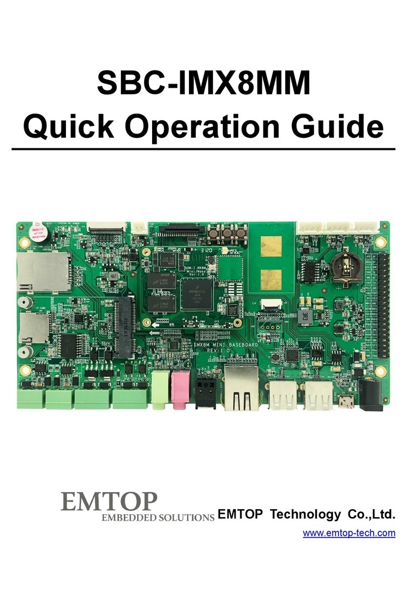
The SOM-ET6ULL BB is a baseboard that design by Emtop tech for the SO
M board SOM-ET6ULL. It features a lot of rich and flexible interfaces. Can be use
d for the customers to develop their user programs, verify their expected functions
and shorten product development cycle. The optional that with a box that can be
used directly by the customer, or they can be customized a box and used this Kit
directly for the productions.
1.2 Hardware Features
1.2.1 SOM-ET6ULL
Electrical Parameters
Working Temperature:0 °C~ 70°C(Commercial)
-45°C~ 85°C(Industrial)
Ambient Humidity:20% ~ 90%, non-condensing
Mechanical Dimensions:60mm x 27mm
Power Input:5V,1.8V/3.3V
Processor
Feature
Details
SOM-i.MX6ULL
Arm Cortex-A7 MPCore platform
Single ARM Cortex-A7 MPCore, including:
•32 KB L1 Instruction Cache
•32 KB L1 Data Cache
•Media Processing Engine (MPE)

5
Co-processor
•General Interrupt Controller(GIC)
•Global Timer
•Snoop Control Unit
•Target frequency of 528MHz
Audio
•S/PDIF Input and Output
•SAI modules supporting I2S,AC97,TDM
On-chip memory
•Boot ROM (96KB)
•Secure/non-secure RAM (32KB)
Memory and storage
DDR SDRAM
•512MB DDR3 SDRAM (16-bit bus width)
•Maximum 1GB support
•800MHz maximum DDR clock
eMMC
•4GB eMMC flash memory default
•8-bits MMC mode
•4~32GB storage option
•Nand or eMMC + SPI option
•256MB ~ 4GB storage option
Expandable flash (MicroSD)
•Meets SD/SDIO 3.0 standard Runs at
4-bits
•Supports system boot from SD card
•Supports high-capacity SDXC card up to
2TB
Network & Wireless
Ethernet
•10/100 Mbps Ethernet Controller
•Up to 2 MAC (6G2, 6G3 Only)
Hardware Interface
•5x UART
•2x ENET

6
I/O connectivity
•1x SDIO
•1x JTAG
•10x GPIOs
•10x SNVS_TAMPER
•2x OTG
Display Interfaces
• 24bits RGB LCD
Camera
• 8Bit CSI
1.2.2 SOM-ET6ULL BB
Electrical Parameters
Working Temperature:0 °C~ 70°C(Commercial)
-45°C~ 85°C(Industrial)
Ambient Humidity:20% ~ 90%, non-condensing
Mechanical Dimensions:135mm x 110mm
Power Input:12V/2A Maximum
Connectivity
2x 80Pin BTB Connector
12V Power Input;
6x USB 2.0 Host
Audio Input/Output
2x 1W Audio Output
2x 10/100Mbps Ethernet
1x RS385
1x CAN
2x DI
2x DO
1x 24Bits RGB LCD
1x TF Card Connector

7
1x MINI PCIe (For 4G module only)
1x SIM Card
1x MicroUSB Connector (For updated only)
1x 16Pin Extension Interface Include SPI, I2C and UART
1x 2.54mm Pin header for UART
1x 2.50mm Box header for Debug
1.3 Mechanical Dimension

8
1.4 Interface Details
1.4.1 DC Power Input
The SOM-ET6ULL BB places a DC Jack to feature a 12V power supply input. The
recommended power supply is 12V/2A. If some customized features are
requested, please contact the sales.
1) Part Reference:J4
2) Not special Pin1 is defined. The center is positive power input, and the negative
pole around.
3) Specification for the DC Jack as below:
1.4.2 USB Host
The SOM-ET6ULL BB order three double-deck USB type A connector to feature
six USB 2.0 host port for users.
1) Part Reference:J7, J9, J10.
2) Not special Pin1 is defined.
3) Specification for the double-deck USB Host as below:

9
1.4.3 Audio Input/Output
The SOM-ET6ULL BB order two 3.5mm audio connector to feature audio input
and audio output function. The audio output can drive a headphone directly and
the audio input can receive audio signal from microphone.
1) Part Reference:J16 for audio in, J13 for audio out.
2) Not special Pin1 is defined. The specification for the audio plug show as below:

10
3) Specification for the double-deck USB Host as below:
1.4.4 2x 1W Speaker Connector
The SOM-ET6ULL BB has two 2.00mm pin pitch 1x2pin WTB connectors that are
used for 1W stereo speaker internal. These interfaces can drive 1W per channel
into 8ΩBTL speaker.
1) Part Reference:J14, J15.
2) Not special Pin1 is defined.
3) Specification for the double-deck USB Host as below:

11
1.4.5 10/100M Ethernet
The SOM-ET6ULL BB feature two 10/100M ethernet. These network ports are
10/100M adaptive.
1) Part Reference:J5, J6.
2) Not special Pin1 is defined.
3) Specification for the double-deck USB Host as below:

12
1.4.6 DIN/DO
The SOM-ET6ULL BB order a 3.81mm double-deck Terminal Block Header to
feature two digital input and digital output. Upper layer features the digital output
and the bottom layer features the digital input.
1) Part Reference:J24
2) Not special Pin1 is defined. The pin define for the digital input/output as below:
Upper
OUT1+
OUT1-
OUT1+
OUT2-
Bottom
12V Out
DIN1
DIN2
DIN GND
3) Specification for the connector for the digital input/output as below:

13
1.4.7 CAN/RS485
The SOM-ET6ULL BB order a 3.81mm double-deck Terminal Block Header to
feature CAN and RS485 function. Upper layer features the CAN interface and the
bottom layer features the RS485 interface.
1) Part Reference:J19
2) Not special Pin1 is defined. The pin define for the CAN/RS485 as below:
Upper
CAN_H
CAN_L
CAN_GND
Bottom
RS485_B
RS485_A
RS485_GND
3) Specification for the connector for the digital input/output as below:

14
1.4.8 LCD
The SOM-ET6ULL BB order a 0.5mm pitch FPC connector to feature the LCD
interface for display. It has a 24bits parallel display interface and include a
resistance touch interface or capacitance touch interface with I2C bus.
1) Part Reference:J17
2) The 0.5mm pitch FPC connector has an special Pin1 defined that shows below.

15
3) The pin defines for the FPC Connector as below:
Pin
Num.
Pin Name
Level
Description
1
DSS_DATA0
3.3V
Display color blue Bit0
2
DSS_DATA1
3.3V
Display color blue Bit1
3
DSS_DATA2
3.3V
Display color blue Bit2
4
DSS_DATA3
3.3V
Display color blue Bit3
5
DSS_DATA4
3.3V
Display color blue Bit4
6
DSS_DATA5
3.3V
Display color blue Bit5
7
DSS_DATA6
3.3V
Display color blue Bit6
8
DSS_DATA7
3.3V
Display color blue Bit7
9
GND
0V
10
DSS_DATA8
3.3V
Display color green bit0
11
DSS_DATA9
3.3V
Display color green bit1
12
DSS_DATA10
3.3V
Display color green bit2
13
DSS_DATA11
3.3V
Display color green bit3
14
DSS_DATA12
3.3V
Display color green bit4
15
DSS_DATA13
3.3V
Display color green bit5
16
DSS_DATA14
3.3V
Display color green bit6
17
DSS_DATA15
3.3V
Display color green bit7

16
18
GND
0V
19
DSS_DATA16
3.3V
Display color red bit0
20
DSS_DATA17
3.3V
Display color red bit1
21
DSS_DATA18
3.3V
Display color red bit2
22
DSS_DATA19
3.3V
Display color red bit3
23
DSS_DATA20
3.3V
Display color red bit4
24
DSS_DATA21
3.3V
Display color red bit5
25
DSS_DATA22
3.3V
Display color red bit6
26
DSS_DATA23
3.3V
Display color red bit7
27
GND
0V
28
DSS_DE
3.3V
Display AC bias enable
29
DSS_HSYNC
3.3V
Display Horizontal Sync
30
DSS_VSYNC
3.3V
Display Vertical Sync
31
GND
0V
32
DSS_PCLK
3.3V
Display pixel clock
33
GND
0V
34
GPIO4
3.3V
X+
35
GPIO3
3.3V
X-
36
GPIO2
3.3V
Y+
37
GPIO1
3.3V
Y-
38
NC
39
NC
40
TP_INT
3.3V
Touch interrupt
41
ACC_INT
3.3V
Touch reset
42
I2C1_SCL
3.3V
I2C bus 1 clock
43
I2C1_SDA
3.3V
I2C bus 1 data
44
GND
0V
45
VDD3V3
3.3V
3.3V for logic
46
VDD3V3
3.3V
3.3V for logic
47
VDD5V
5V
5V for backlight
48
VDD5V
5V
5V for backlight
49
LCD_RST
3.3V
LCD Reset
50
BKLGHT_PWM
3.3V
Backlight PWM output
4) Specification for the 50 Pin FPC connector as below:

17
1.4.9 Reset
The SOM-ET6ULL BB has a reset key to cause a cold reset for the board.
1) Part Reference:S1
2) Not special Pin1 is defined. Press the button will reset the board directly.
3) Specification for the reset button as below:

18
1.4.10 User Button
The SOM-ET6ULL BB has a user button key to for interrupt input. Short press the
user button will generate an interrupt and long press the user button will turn
down the system.
1) Part Reference:SW1
2) Not special Pin1 is defined.
3) Specification for the user button as below:

19
1.4.11 LED Indicator Light
The SOM-ET6ULL BB has a 2x4 LED array indicator light to indicate the state of
the board. These LED will indicate the power, system running, 4G running and
the internet connecting.
1) Part Reference:LED1, LED2.
2) Not special Pin1 is defined. The defines for the LED as below table.

20
LED
LED2
LED1
1
System/User LED
Power
2
User LED
4G 1PPS
3
ETH1 ACT
ETH1 Link
4
ETH0 ACT
ETH0 Link
3) Specification for the user button as below:
1.4.12 TF Card
The SOM-ET6ULL BB has a TF Card connector to install a media card. This
media card can be used for data storage or for firmware.
1) Part Reference:J18.
2) Not special Pin1 is defined.
3) Specification for the user button as below:
Table of contents
Other EMTOP Computer Hardware manuals
Popular Computer Hardware manuals by other brands

EK-Quantum
EK-Quantum Momentum2 ROG Strix X570-i Gaming D-RGB user guide

HP
HP A4800A Technical documentation
XESS
XESS XStend XS40 user manual
Delta Electronics
Delta Electronics AC Motor Drive VFD-M user manual
Alphacool
Alphacool Eisblock Aurora Acryl RX 7900XTX/XT Toxic quick start guide
Cawomat
Cawomat 2000 IR Reference manual
