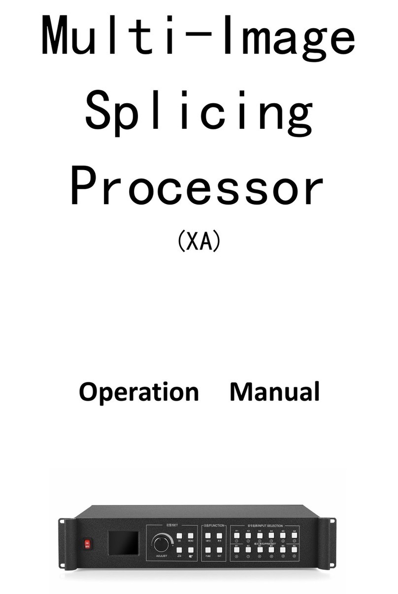
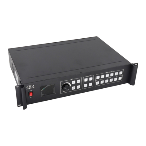
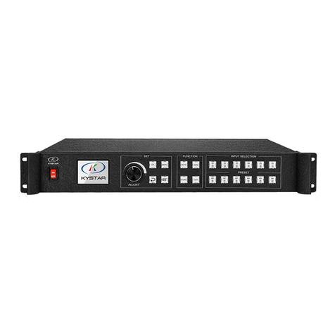
Kystar LS16 User manual

Sixteen port 2 in 1 controller LS16
Version: V2.3
Release Date: November 2021
使用说明书

Version record
version number
Change details
release time
V1.0
First edition released
2019.08.18
V2.0
Modify device interface description information
Modify device picture
Modify device function description
Adjusting the K-HDR support source
Modify equipment debugging steps
Unified arrangement of 16 network ports layout,
2020.12.09
V2.1
Modify K-HDR function description
2021.10.15
V2.2
Modify the cover
2021.10.25
V2.3
Correct size data
2021.11.18

Summary
Ls16 is a splice control processor designed for live performance LED large screen. It adopts the industry's
top design technology and conforms to international and industry standards. It's industry support 4K@60Hz Input
2U device. Support k-hdr, make ordinary SDR material present HDR display effect, solve the pain of less HDR
material.
The whole machine has 9.6 million pixels of customized load, which meets most of the field needs.
Functional features
The single network port has a load of 650000 pixels, the maximum load of the whole
machine is 9600000 pixels, the maximum width can reach 16000 points, and the maximum
height can reach 8000 points. The single machine has 16 network port output
A total of 8 input signals including dvix2, hdmix3, dpx2 and sdix1 can be accessed, among
which DP1, DP2 and HDMI3 can support 3840x2160@60Hz or 7680x1080@60Hz input
Support 8 screen display, screen position arbitrary layout, support arbitrary video capture
Pure hardware FPGA Architecture: no CPU, no kernel, no poisoning and crash risk, the
system runs stably. MTBF > 30000 hours, support 365 × 24-hour continuous operation
All layers support matting and transparency adjustment for the best effect
Support signal source hot backup
Humanized interactive control interface, with front-end switch, LCD information color
screen, crystal keys and knobs
EDID configuration management: support the reading, modification and customization of
EDID (extended display identification data)
Support one button black screen / still
Black edge removal / clipping function: solve the problem of black edge generated by
front-end signal, and make arbitrary clipping for any signal source (still maintain full screen
state)
Support key locking to prevent misoperation
Color restore settings: in the client software with color restore settings options
Support K-HDR, make common SDR material present HDR display effect, solve the pain of
less HDR material
Monitor port output supports both monitor input and output at the same time, and supports
configuration to look back at output.

catalog
I. PRODUCT DISCUSSIONS....................................................................................................................1
II、PRODUCT CHARACTERISTICS........................................................................................................2
III. TECHNICAL INDICATORS...........................................................................................................3
IV、WORKING SKETCH......................................................................................................................... 4
V. PANEL STRUCTURE............................................................................................................................5
FRONT PANEL...........................................................................................................................................5
BACK PANEL............................................................................................................................................. 6
VI.WIRING AND INSTALLATION.......................................................................................................... 7
WIRING DIAGRAM.................................................................................................................................. 7
INSTALLATION STEPS................................................................................................................................. 7
VIII EQUIPMENT COMMISSIONING...............................................................................................8
IX、FREQUENTLY ASKED QUESTIONS............................................................................................. 15

LS16 manual www.kystar.com.cn
1
I. Product Discussions
With the rapid development and application demand of LED display industry, various control
requirements for large screen control system emerge as the times require. However, due to the
limitations of the large screen control system in image processing, picture control and signal
format conversion, there are some weak links in the large screen control system of LED, which
can not meet the needs of users. The main problems are as follows:
1.The signal source access format of large LED screen control system is limited. At present,
only digital DVI signal is commonly used. Many signal sources (such as VGA) can not be
displayed directly on the large LED screen through the control system.
2.The image processing effect of traditional signal acquisition card is poor, which causes
great loss to the clarity of the picture while converting the signal format.
3.The large LED screen control system can only capture the corresponding points of the large
LED screen for display, while in some customer sites, it is necessary to display any size or
complete computer desktop screen at will.
4.The large LED screen control system can only capture the corresponding points of the large
LED screen for display, while in some customer sites, it is necessary to display any size or
complete computer desktop screen at will.
In view of the above problems, our company independently developed a number of video
processing products. The product adopts advanced control and image processing technology,
which can not only realize switching between signals quickly and steadily, but also process
multi-level pictures. In addition, the product can be controlled by keyboard and PC computer on
the device, which makes the operation simple and convenient.

LS16 manual www.kystar.com.cn
2
II、Product characteristics
The single network port has a load of 650000 pixels, the maximum load of the whole
machine is 9600000 pixels, the maximum width can reach 16000 points, and the maximum
height can reach 8000 points. The single machine has 16 network port output
A total of 8 input signals including dvix2, hdmix3, dpx2 and sdix1 can be accessed, among
which DP1, DP2 and HDMI3 can support 3840x2160@60Hz or 7680x1080@60Hz input
Support 8 screen display, screen position arbitrary layout, support arbitrary video capture
Pure hardware FPGA Architecture: no CPU, no kernel, no poisoning and crash risk, the
system runs stably. MTBF > 30000 hours, support 365 × 24-hour continuous operation
All layers support matting and transparency adjustment for the best effect
Support signal source hot backup
Humanized interactive control interface, with front-end switch, LCD information color
screen, crystal keys and knobs
EDID configuration management: support the reading, modification and customization of
EDID (extended display identification data)
Support one button black screen / still
Black edge removal / clipping function: solve the problem of black edge generated by
front-end signal, and make arbitrary clipping for any signal source (still maintain full screen
state)
Support key locking to prevent misoperation
Color restore settings: in the client software with color restore settings options
Support K-HDR, make common SDR material present HDR display effect, solve the pain of
less HDR material
Monitor port output supports both monitor input and output at the same time, and supports
configuration to look back at output.

LS16 manual www.kystar.com.cn
3
III. Technical Indicators
The 16 network port two-in-one controller adopts the latest patented video processing
technology, and has the video conversion capability of any format input and corresponding format
output. Signals including DVI, HDMI, DP and SDI can be processed and enhanced to meet
customer application requirements. The detailed specifications are as follows:
Input port
Type
number
Specifications
DVI
2
1.3 standard, maximum support 1920 × 1080@60Hz
SDI(BNC)
1+1(LOOP)
Support SD/HD/3G-SDI
HDMI
2
1.3A standard, maximum support 1920 × 1080@60Hz
HDMI2.0
1
Hdmi 2.0 standard, up to 3840 × 2160@60Hz or 7680x1080@60Hz
DP1.2
2
DisplayPort 1.2 standard, maximum support 3840 ×
2160@60Hz or 7680x1080@60Hz
Output port
Type
number
Specifications
LAN
16
LAN port, used to transmit data to receiving card, with a maximum load
of 960000
DVI-I
(MONITOR)
1
Monitor port, resolution 1920 × 1080@60Hz
Control port
Type
number
Specifications
USB(Type-B )
1
USB-cfg interface is used to connect PC to control
RS-232(DB-9)
1
The data transmission rate is 50、75、100、150、300、600、1200、
2400、4800、9600、19200、38400 (BT)
RJ-45
1
100M
Whole machine specification
Input power
100-240V AC~50/60Hz 0.6A
working temperature
0-45℃
Dimensions
488×360×89mm(L×W×H)
Net weight
6KG
Overall power consumption
55W

LS16 manual www.kystar.com.cn
5
V. Panel Structure
Front panel
1. LCD---------------Text display screen, displaying menus, parameters and other information
2. Knob--------------------------------------Knob increase and decrease key, press to confirm
3. OK -----------------------------------------------------------------------Enter
4. MENU----------------------------------------------------------------------menu
5. MAIN-1------------------------------------------------------------------Main screen-1
6. MAIN-2------------------------------------------------------------------Main screen-2
7. PIP-1-----------------------------------------Picture-in-Picture-1; open window button
8. PIP-2-------------------------Picture-in-picture-2; open window button; number key 1
9. PIP-3---------------------------Picture-in-Picture-3; open window button; number button 2
10.PIP-4-------------------------Picture-in-Picture-4;open window button; number key 3
11.PIP-5-------------------------Picture-in-Picture-5;open window button; number key 4
12.PIP-6-------------------------Picture-in-Picture-6; open window button; number key 5
13.CLEAR-----------------------------------------------------------Delete screen button
14.BLACK------------------------------------------------------Normal and black screen switch
15.LOAD----------------------------------------------------------Preset recall button
16.ESC----------------------------------------------------------------------Back button
17.LOCK---------------------------------------------------------------------Key lock
18.HDMI1---------------------------------------------------------------Signal source HDMI-1
19.HDMI2----------------------------------------------------------------Signal sourceHDMI-2
20.HDMI3----------------------------------------------------------------Signal sourceHDMI-3
21.DP-1-------------------------------------------------------Signal source DP-1;number key6
22.DP-2-------------------------------------------------------Signal source DP-2;number key7
23.DVI-1-----------------------------------------------------Signal source DVI-1;number key8
24.DVI-2-----------------------------------------------------Signal source DVI-2;number key9
25.SDI-------------------------------------------------------Signal source SDI;number key10
26.SENDER----------------------------------------Related operation buttons of control system
27.FREEZE--------------------------------------------------------------------Freeze picture
28.SAVE----------------------------------------------------------------------Save preset

LS16 manual www.kystar.com.cn
6
back panel
1. POWER---------------------------------------------------------------------Device switch
2. SDI-------------------------------------------------SDI HD signal input port; ring exit
3. HDMI1-HDMI3----------------------------------------------------------HDMI Input channel
4. DP1 and DP2------------------------------------------------------------DP input channel,
5. DVI MONITOR-------------------------------------------------------------Monitoring port
6. DVI1 and DVI2----------------------------------------------------------DVI Input channel
7. NET--------------------------------------------------------------------RJ45 Network port
8. COM-----------------------------------------------------------------------------COM port
9. USB-CFG------------------------------------------------------------Serial debugging port
10. AC-------------------------------------------------------------------------Power socket
11. NET1-8------------------------------------------------------------------Network port1-8
12. NET2-16----------------------------------------------------------------Network port9-16

LS16 manual www.kystar.com.cn
7
VI.Wiring and Installation
Wiring diagram
Installation steps
1. Wiring as shown, the HDMI port of the graphics card is connected to the HDMI input interface
of the 2-in-1 controller;
2. Wiring as shown in the figure, using a network cable to connect the output network port of the
2-in-1 controller to the receiving card;
3. Wiring as shown in the figure, use a USB debugging cable to connect the USB port of the
computer to the serial port of LS16;
4. Make sure the wiring is correct and power on and turn on the 2-in-1 controller.
USB control cable
LED screen
Signal source
Power cable
Ethernet net
Ethernet net

LS16 manual www.kystar.com.cn
8
VIII Equipment commissioning
LS16 has 16 Ethernet ports output, and the 16 network ports can be arranged arbitrarily. The
load of the whole machine is determined by the device splice mode and output resolution,
and that more then the LED screen resolution. For example, cross splice, the output
resolution is 1920*1080, then the load of the whole machine is 3840*2160
1.Video processor debugging
(1)Set output resolution
The output resolution function module can define the load and output frequency of each
part of the output port of LS16. The output resolution have regular resolution and custom
resolution. The custom resolution is that you can define the resolution of each output port
according to specific needs when the conventional resolution does not meet the conditions.
(2)splice mode
The splicing mode function module contains 3 options: horizontal splicing, vertical splicing, and cross
splicing. Select the appropriate mode according to the distribution of the loading area of the sending card behind
the LED screen.
Horizontal stitching: The 4 output ports of the stitcher are arranged horizontally and stitched into a complete
image.
Vertical splicing: The 4 output ports of the splicer are vertically arranged and spliced into a complete image.
Field word stitching: The four output ports of the splicer are stitched together into a complete image.

LS16 manual www.kystar.com.cn
9
(3)window layout
The screen layout function module contains eight fixed layout templates. The layout of the
layers opened through the screen layout is fixed.
Layout 1: open a single layer, one layer covers the entire screen. (Or keep press the MAIN-1
button open window)
Layout 2: Open two layers, the layer arrangement is as shown in the figure below.(Or keep
press the MAIN-2 button open window)
Layout 3 and layout 4 and so on.
(4)Image parameters(window size)
1) On the image parameter page, the following operations can be performed
2) Information display: You can view the information and input source status of the
current screen.
3) Input source switching: You can switch the signal source on this page.
4) Image Parameters: Set the image size and position.
5) Local Settings: Set the position and size of the local interception。
6) Panorama partial switch: used to switch the panorama or partial picture displayed
on the current screen.
7) Advanced Settings: You can set the cutout, transparency, and level of the current
image.

LS16 manual www.kystar.com.cn
10
(5)save setting
The currently set parameters can be saved to the device mode, which is convenient for direct
recall in the future. 32 patterns can be saved.
2.software debugging
The software debugging is the control system debugging page. After debugging the control
system, it is necessary to set the splicing method, loading information and screen resolution of the
four output through the LS16 hardware panel or the software video processor interface.
he following shows the debugging interface of KYSTAR control system, without in-depth
main control system debugging explanation. If you need to do main control system debugging,
you can refer to the KYSTAR control system software setting manual.
(1)Software detects sending device and receiving card
(2)Send device interface without setting

LS16 manual www.kystar.com.cn
11
(3)Receiving card parameter interface
First select the module manufacturer: select the corresponding module manufacturer; the
specifications of the modules, the driver chip and the decoding method should be consistent
Set receiving card Card Load:width and height of the Receiving card
Effect debugging: Debug data clock frequency and multiplier, debug refresh to 1920 (PWM
chip debug gray clock frequency, refresh to 3840)
Effective means to improve the display effect:

LS16 manual www.kystar.com.cn
12
1、Increase the data clock: the frequency is not affected by other parameters, which is the
first condition; if there is a blurry screen, reduce it one by one; try to adjust the clock phase if it is
slightly blurred; 32-scan modules are generally adjusted to 20.83; too high has a greater impact on
the module itself. Large and troublesome to maintain.
2、Decrease the OE width: the default is 32ns, in units of 8, decrease one by one; note that
too low will affect the low gray effect.
3、Adjust the output gray level: conventional modules, generally adjusted to 12-14; 12
represents the 12th power of 2, that is, 4096.
4、Appropriately reduce the parameter value, and then save: After the display effect is
normal, reduce the above data appropriately without affecting the refresh rate and brightness
efficiency. At present, it is to reduce power consumption and increase the life of the screen.
Note: Display scheme, generally use refresh priority, the disadvantage is that it may lead to
poor low gray effect. Grayscale priority is good for see directly
(4)Screen connection interface
Single card setting: set the receiving card load size
Network port selection: select the corresponding network port settings
screen connection mode (horizontal/vertical): the connection mode between the receiving card and
the receiving card
Setting :According to the flickering of the screen, click the corresponding area to intelligently
identify the connection method of the network port and network cable.
Complex display connection: used to individually adjust the load and location information of each
receiving card
(5)Separate save the sending device, receiving card parameters and display connection. If the
parameters of all receiving cards are unified, you can use all curing. If the parameters are not
unified, you need to cure separately. You can right-click the curing button to cure individually.
Before using the one-key repair function, it must be fully cured before using the one-key
repair function after replacing the device.

LS16 manual www.kystar.com.cn
13
VX Control menu
Advanced menu
language
settings
Chinese
ENGLISH
Factory settings
Ok
Cancel
Mode
deletion
single delete
delete continuously
Multi-machine
cascade
Close
Open
signal loss
concealment
Close
Open
Communication
settings
Com set
IP set
K-HDR
select input source
Network port settings
Monitoring port
settings
monitor single input
monitor input and output
Network port settings
Set the size and coordinates of each network
port
1.language settings
switch the language displayed on the hardware panel of the device,
2.Factory
Restore the setting information stored in the machine to the factory state, please be careful
in this operation.
3.Mode delete
Delete the pattern data stored in the device, select single deletion or continuous deletion.
Single delete: select the mode number, delete after confirmation.
Continuous deletion: Set the mode start number and end number, and delete after
confirmation.

LS16 manual www.kystar.com.cn
14
4.Multi-machine cascade
It is used for splicing large screens with multiple devices and can be turned on and off on
here.
After it is turned on, turn to the synchronization source selection page. All input sources of
the current device can be set as synchronization sources, and the input source where the blue
background is located is the input source selected by the current device.
5.signal loss concealment
When the input source is lost, the screen window where it is located is automatically hidden,
which can be used for multi-screen and multi-input source backup to avoid black screen caused by
signal loss.
6.Communication settings
Serial port settings: including baud rate, parity bit, data bit, stop bit and other information.
The default serial port is COM port; the default baud rate is 115200; the default parity bit is
NONE; the default data bit is 8; the default stop bit is 1.
IP settings: IP address, subnet mask, gateway can be set. The default IP address is
192.168.0.100; the default subnet mask is 255.255.255.0; the default gateway is 192.168.0.254.
7.K-HDR
K-HDR is a unique technology of Kystar , which can improve the current image display and
achieve the effect of HDR.
Input source selection: DVI1, DP1, HDMI3, other input sources do not support K-HDR.
Please select the input source reasonably.
K-HDR function switch: Used to turn on and off the K-HDR function of the current device.
K-HDR function level: The K-HDR display effect can be adjusted at levels 0-31. The larger
the number, the more obvious the effect. Users can choose according to the actual situation. The
default value is 8.
K-HDR effective area switch: You can choose the K-HDR effective display area as global or
local. If you select global, it will take effect immediately within the screen display range. If you
select local, enter the effective area parameter setting page. The default is global.
K-HDR effective area parameters: You can set the width, height, starting row and starting
column parameters of the effective area.
K-HDR demo mode: After the demo mode is turned on, the K-HDR and non-HDR effects are
automatically displayed side by side on the screen.
8.Monitoring port settings
DVI monitoring port can be set to monitor a single input signal or monitor input and output
signals.

LS16 manual www.kystar.com.cn
15
IX、frequently asked questions
Q1:DVI、HDMI、DP、SDI Port definition。
A:
DVI: Digital (high-definition) video signal is an interface standard introduced by Silicon Image,
Intel (Intel) and other companies in 1999 to form the DDWG (Digital Display Working Group). It
has been carried out in terms of speed, resolution and HDCP protocol. Optimize well. The signal
source is generally a desktop computer, a notebook, etc.;
HDMI: High-definition multimedia interface is a digital video/audio interface technology. It is a
dedicated digital interface suitable for image transmission. It can transmit audio and video signals
at the same time. The maximum data transmission speed is 5Gbps. The signal source is generally a
camera, a notebook, an information distribution system, etc.
DP: DisplayPort interface, a high-definition audio and video stream transmission interface. It is
also the main interface standard for future display devices and will replace the current DVI and
VGA, and even HDMI.
SDI: Acronym for serial digital interface. The serial interface is an interface that sequentially
transmits each bit of the data word and the corresponding data through a single channel. Due to
the high data rate of serial digital signals, they must be processed before transmission.
Q2:Briefly describes the connection mode of video card, video processor, receiving
card and large LED screen.。
A: The video card's DVI (VGA) output port is connected to the DVI-IN (VGA-IN) input of the
video processor. The output of the video processor's network port is connected to the terminal
receiving card behind the screen through the network cable. The receiving card connects and
controls part of the screen and cascades the whole screen
Q3:What are the reasons why the host computer can not detect the device?
A: It is necessary to connect its command transmission line to control the video processor
with a trial computer. That is the serial line.
Failure to connect may be caused by the following conditions.
①The device is not powered on;

LS16 manual www.kystar.com.cn
16
②The USB cable driver is not installed in the computer or the USB driver is damaged;
③The serial cable is not connected well or the cable is damaged;
If the above suggestions do not finally solve your problem, please contact our company's
customer service staff in time. We will assist you to solve the problems encountered within the
first time.
Q4:The screen appears black after the computer is connected to the video processor input
source。
A: ①The problem of the signal source. When connecting the computer graphics card, you
need to set the copy mode of the graphics card. If you do not set it, the DVI port of the graphics
card does not output data. Setup steps: turn off the power of the video processor-re-plug the video
card to the video processor-ATI graphics card automatically reads the copy mode, NVIDIA
graphics card needs to enter the graphics card control center, set up multiple monitors +
dual-screen copy mode.
②The problem with the connection cable. When the signal cable interface is not in
good contact or there is a problem inside the wire, abnormal phenomena such as color bars and
flower screens will appear on the large screen. Carefully check whether the pin in the signal cable
is broken or slanted and replace the signal cable;
If the above suggestions do not finally solve your problem, please contact our company's
customer service staff in time. We will assist you to solve the problems encountered within the
first time.
Table of contents
Other Kystar Computer Hardware manuals
Popular Computer Hardware manuals by other brands

MSI
MSI LIQUID COOLING Series installation guide

DeLOCK
DeLOCK 47199 user manual

ekwb
ekwb EK-D5 Dual TOP CSQ INSTALLATION AND MOUNTING MANUAL

Lattice Semiconductor
Lattice Semiconductor CrossLink-NX user guide

Adaptec
Adaptec RAID 5085 Installation and user guide

Matrox
Matrox Axio Installation and user guide

Crestron
Crestron C2ENET-1 Operations & installation guide

Ultra Products
Ultra Products X-Wind High Performance CPU Cooler ULT33049 Specification sheet

Motorola
Motorola ONCE SC140 Application note

Siemens
Siemens Simatic VS 710 Quick reference guide

ST
ST X-NUCLEO-53L7A1 user manual

KanexPro
KanexPro SW-4KPROSLIM4X1 user manual