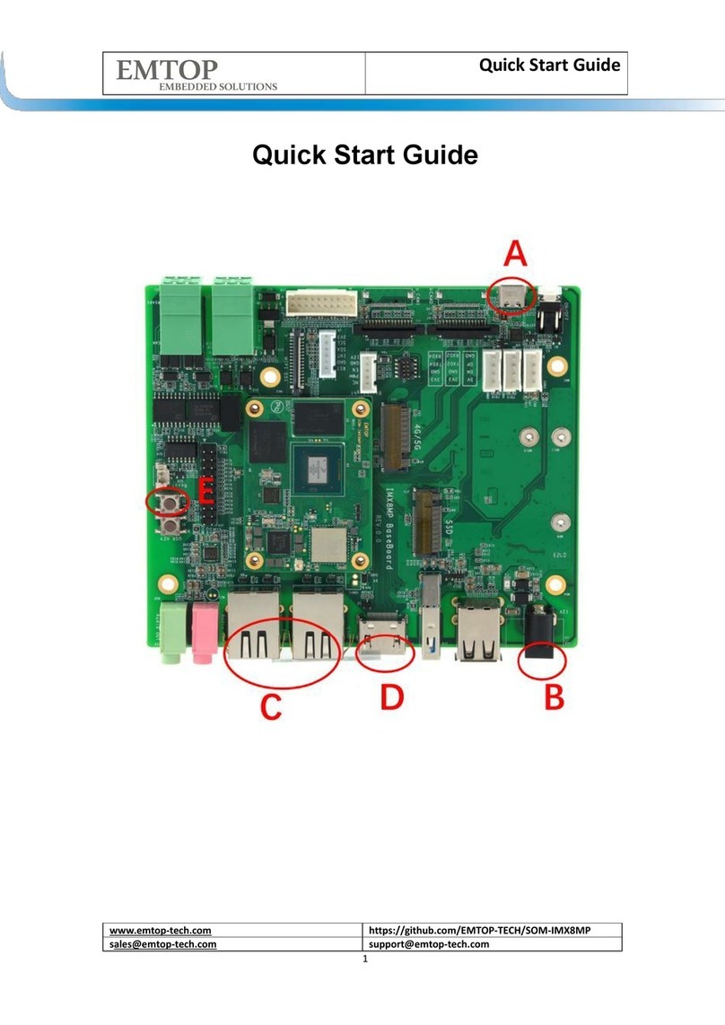
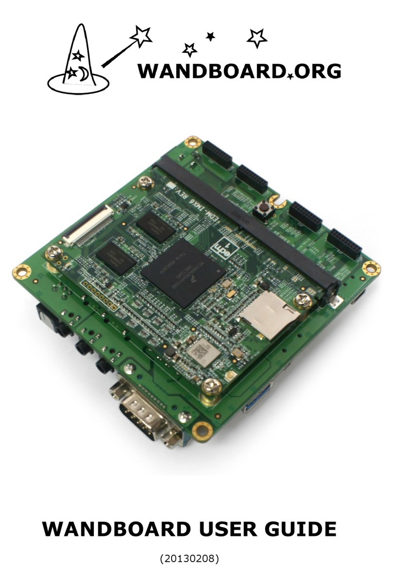
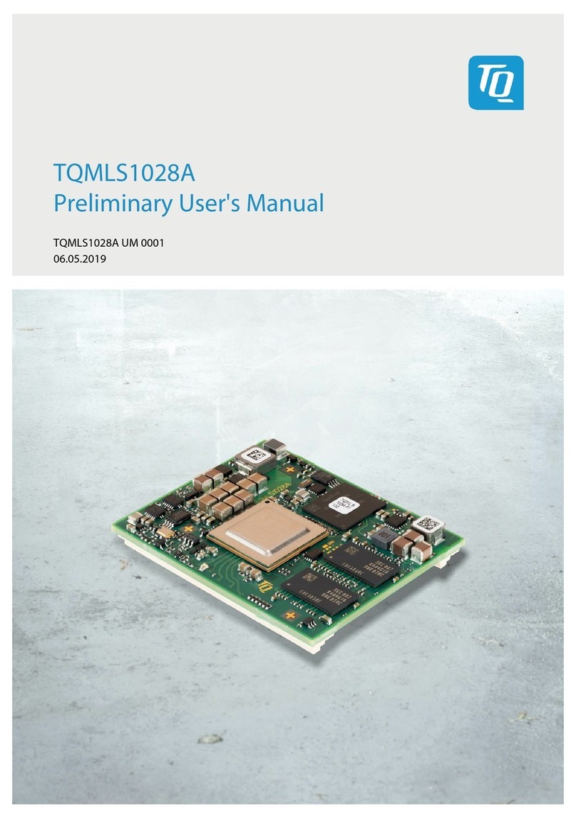
EMTOP SBC-IMX8MP Instructions for use

www.emtop-tech.com
https://github.com/EMTOP-TECH/SOM-IMX8MP
SOM-IMX8MP Hardware User Manual
3
Table of Contents
TABLE OF CONTENTS ................................................................................................ 3
1 INTRODUCTION ..........................................................................................................5
2 HARDWARE FEATURES .............................................................................................. 5
2.1 SOM-IMX8MP .................................................................................................. 5
2.2 IMX8MP BaseBoard .........................................................................................6
3 MECHANICAL DIMENSION ...........................................................................................8
4 INTERFACE DETAILS .................................................................................................. 9
4.1 DC Power Input ................................................................................................9
4.2 USB 2.0 Host ..................................................................................................10
4.3 Audio Input/Output ......................................................................................... 10
4.4 10/100/1000M Ethernet ..................................................................................11
4.5 DIN/DO ........................................................................................................... 12
4.6 CAN/RS485 ....................................................................................................13
4.7 LVDS .............................................................................................................. 14
4.8 Touch .............................................................................................................. 16
4.9 Backlight .........................................................................................................17
4.10 Power Button ................................................................................................19
4.11 TF Card .........................................................................................................20
4.12 4G/5G ........................................................................................................... 22
4.13 NVME ........................................................................................................... 23
4.14 2.54mm Extension Interface ........................................................................ 24
4.15 USB Extension Interface ..............................................................................25
4.16 Debug Extension ..........................................................................................26
4.17 Debug Port ................................................................................................... 27
4.18 Camera CSI0 ................................................................................................28
4.19 Camera CSI1 ................................................................................................30

www.emtop-tech.com
https://github.com/EMTOP-TECH/SOM-IMX8MP
SOM-IMX8MP Hardware User Manual
4
4.20 MIPI DSI ....................................................................................................... 32
4.21 HDMI ............................................................................................................ 34
4.22 USB3.0 Host .................................................................................................34
4.23 Jtag ...............................................................................................................35

www.emtop-tech.com
https://github.com/EMTOP-TECH/SOM-IMX8MP
5
1 Introduction
The IMX8MP BaseBoard is a baseboard that design by Emtop tech for the SOM
board SOM-IMX8MP. It features a lot of rich and flexible interfaces. Can be used for the
customers to develop their user programs, verify their expected functions and shorten
product development cycles. The optional that with a box that can be used directly by the
customer, or they can be customized a box and use this Kit directly for the productions.
2 Hardware Features
2.1 SOM-IMX8MP
Form Factor
50mm x 40mm x 7.3 mm
Processor Unit
NXP Quad core Cortex-A53 (ARM v8) 64-bit SoC
@ 1.8GHz for Commercial
@1.6GHz for Industry
2.3 TOP/s Neural Network performance available for user
applications
ARM Cortex-M7 Core CPU operating up to 800 MHz
375 Mpixel/s HDR Image Sensor Processor ISP
Hifi4 Audio DSP, operating up to 800 MHz
H.265 / H.264 (up to 1080p60 encode and decode),
OpenGL ES 3.0 graphics, OpenCL 1.2
Graphics/GPU
3D Graphics: GC7000L
2D Graphics: GC520L
Video Codec/VPU
1080p60 VP9
1080p60 HEVC/H.265 decoder
1080p60 AVC/H.264 Baseline, Main, High decoder
1080p60 VP8
1080p60 AVC/H.264 encoder
1080p60 VP8
TrustZone support
Memory
2GB LPDDR4 on board (Support Up to 8GB Max)
Storage
16GB eMMC on board (Support Up to 64GB Max)
64Mb SPI Nor Flash

www.emtop-tech.com
https://github.com/EMTOP-TECH/SOM-IMX8MP
6
2.2 IMX8MP BaseBoard
Carrier Board Unit
Connectivity:
WiFi/BT Combo(on SOM)
2x GbE LAN port
1x RS485
1x CANFD
Ethernet/Wireless
Onboard certified radio module with:
2.4 GHz, 5.0 GHz IEEE 802.11 b/g/n/ac wireless
Bluetooth 5.1, BLE
2x Gigabit Ethernet controller
One Gigabit Ethernet controller with PHY on-board
supporting IEEE 1588
One Gigabit Ethernet controller supporting IEEE 1588,
PHY is needed on baseboard
Connectivity
1× PCIe 1-lane Host, Gen 3 (5Gbps)
2× USB 3.0 port ( high speed )
1x SDIO, eMMC 5.1
66× GPIO supporting:
Up to 3× UART
Up to 4× I2C
Up to 2x SPI
1x SDIO interface
2x CANFD
1x PCM
Up to 4 x PWM channels
Display
1x HDMI 2.0a ports (up to 1920 x 1080p60 supported)
1x 4-lane MIPI DSI (4-lane up to 1920 x 1080 at 60Hz)
1x 4-lane LVDS (up to approximately 1366x768p60)
Image Capture
2x 4-lane MIPI CSI-2
Audio Interface
SPDIF input and output
Five external synchronous audio interface (SAI) modules
8-channel PDM microphone input
SPDIF input and output
Dimensions
50mm x 40mm x 7.3 mm
Operating Temperature
Commercial Version: 0°C-70°C
Industrial Version: -45°C-85°C
Power
Single +5V Power supply input.

www.emtop-tech.com
https://github.com/EMTOP-TECH/SOM-IMX8MP
7
2x TTL(Include Debug)
1x Debug
1x PCIe(M2 Key M)
1x I2C(For Touch), 1x PWM(For Backlight), 1xRTC
(For Battery)
I/O
Interfaces:
14x GPIOs
2x DIN
2x DO
USB:
2x USB2.0 host
1x USB3.0 host
1x M2 Key B(USB3.0)
Display:
1x HDMI2.0a(1920 x 1080p60)
1x MIPI DSI
1x LVDS(single channel)
Media:
2x MIPI CSI
Audio IN/Out
Power supply:
12V/2A typical
Mechanical:
135.3x113mm

www.emtop-tech.com
https://github.com/EMTOP-TECH/SOM-IMX8MP
9
4 Interface Details
4.1 DC Power Input
The IMX8MP BASEBOARD places a DC Jack to feature a 12V power supply
input. The recommended power supply is 12V/2A. If some customized features
are requested, please contact the sales.
1) Part Reference:J26
2) Not special Pin1 is defined. The center is positive power input, and the negative
pole around.
3) Specification for the DC Jack as below:

www.emtop-tech.com
https://github.com/EMTOP-TECH/SOM-IMX8MP
10
4.2 USB 2.0 Host
The IMX8MP BASEBOARD order one double-deck USB type A connector to
feature 2 USB 2.0 host port for users.
1) Part Reference:J17.
2) Not special Pin1 is defined.
3) Specification for the double-deck USB Host as below:
4.3 Audio Input/Output
The IMX8MP BASEBOARD order two 3.5mm audio connector to feature audio
input and audio output function. The audio output can drive a headphone directly
and the audio input can receive audio signal from microphone.
1) Part Reference:J25 for audio in, J24 for audio out.
2) Not special Pin1 is defined. The specification for the audio plug show as below:

www.emtop-tech.com
https://github.com/EMTOP-TECH/SOM-IMX8MP
11
3) Specification for the audio connectors as below:
4.4 10/100/1000M Ethernet
The IMX8MP BASEBOARD feature two 10/100/1000M ethernet. These network
ports are 10/100/1000M adaptive.
1) Part Reference:J2(ETH0), J3(ETH1).
2) Not special Pin1 is defined.
3) Specification for the RJ45 as below:

www.emtop-tech.com
https://github.com/EMTOP-TECH/SOM-IMX8MP
12
4.5 DIN/DO
The IMX8MP BASEBOARD order a 3.81mm double-deck Terminal Block Header
to feature two digital input and digital output. Upper layer features the digital
output and the bottom layer features the digital input.
1) Part Reference:J23
2) Not special Pin1 is defined. The pin define for the digital input/output as below:
Upper
DIN1
DIN2
GND
Bottom
DOUT1+
COMMON
DOUT2+
3) Specification for the connector for the digital input/output as below:

www.emtop-tech.com
https://github.com/EMTOP-TECH/SOM-IMX8MP
13
4.6 CAN/RS485
The IMX8MP BASEBOARD order a 3.81mm double-deck Terminal Block Header
to feature CAN and RS485 function. Upper layer features the CAN interface and
the bottom layer features the RS485 interface.
1) Part Reference:J21
2) Not special Pin1 is defined. The pin define for the CAN/RS485 as below:
Upper
CAN_L
CAN_H
CAN_GND
Bottom
RS485_A
RS485_B
RS485_GND
3) Specification for the connector for the digital input/output as below:

www.emtop-tech.com
https://github.com/EMTOP-TECH/SOM-IMX8MP
15
3) The pin defines for the LVDS Connector as below:
Pin
Num.
Pin Name
Level
Description
1
PWR_LVDS
--
Power for panel, 3.3/5V
optional
2
PWR_LVDS
--
Power for panel, 3.3/5V
optional
3
GND
Ground
Ground
4
GND
Ground
Ground
5
LVDS0_TX0_N
Differential signal negative
6
LVDS0_TX0_P
Differential signal positive
7
GND
Ground
8
LVDS0_TX1_N
Differential signal negative
9
LVDS0_TX1_P
Differential signal positive
10
GND
Ground
11
LVDS0_TX2_N
Differential signal negative
12
LVDS0_TX2_P
Differential signal positive
13
GND
Ground
14
LVDS0_CLK_N
Differential signal negative
15
LVDS0_CLK_P
Differential signal positive
16
GND
Ground
17
LVDS0_TX3_N
Differential signal negative
18
LVDS0_TX3_P
Differential signal positive
19
SEL1
10K pull down default
20
SEL2
10K pull down default
4) Specification for the 20pin 2.00mm connector as below:

www.emtop-tech.com
https://github.com/EMTOP-TECH/SOM-IMX8MP
16
4.8 Touch
The IMX8MP BASEBOARD order a 2.00mm pitch connector to feature the touch
interface for LVDS. It can be used for other purpose if not require a touch function.
Please note that the touch signals are shared with the MIPI display
1) Part Reference:J5
2) The 2.00mm pitch connector has an special Pin1 defined that shows below.
3) The pin defines for the touch Connector as below:
Pin
Num.
Pin Name
Level
Description
1
3V3
--
3.3V power output
2
CTP_SCL
--
I2C2 clock
3
CTP_SDA
Ground
I2C2 data
4
CTP_INT
Ground
Interrupt for touch
5
GND
Ground
6
CTP_RST
Reset output for touch

www.emtop-tech.com
https://github.com/EMTOP-TECH/SOM-IMX8MP
17
4) Specification for the 20pin 2.00mm connector as below:
4.9 Backlight
The IMX8MP BASEBOARD order a 2.00mm pitch connector to feature the
backlight interface for LVDS. It can be used for other purpose if not require a
backlight.
1) Part Reference:J7
2) The 2.00mm pitch connector has an special Pin1 defined that shows below.

www.emtop-tech.com
https://github.com/EMTOP-TECH/SOM-IMX8MP
18
3) The pin defines for the touch Connector as below:
Pin
Num.
Pin Name
Level
Description
1
12V
--
12V power output
2
GND
Ground
3
EN
3.3V
Blacklight enable
4
PWM
3.3V
PWM output for backlight
5
NC
No connection
4) Specification for the 20pin 2.00mm connector as below:

www.emtop-tech.com
https://github.com/EMTOP-TECH/SOM-IMX8MP
19
4.10 Power Button
The IMX8MP BASEBOARD has a button key to for interrupt input or power on/off.
Short press the user button will generate an interrupt and long press the user
button will turn down the system.
1) Part Reference:SW1
2) Not special Pin1 is defined.
3) Specification for the user button as below:

www.emtop-tech.com
https://github.com/EMTOP-TECH/SOM-IMX8MP
20
4.11 TF Card
The IMX8MP BASEBOARD has a TF Card connector to install a media card. This
media card can be used for data storage or for firmware.
1) Part Reference:J18.
2) Not special Pin1 is defined.
3) Specification for the user button as below:
Other manuals for SBC-IMX8MP
1
This manual suits for next models
1
Table of contents
Other EMTOP Single Board Computer manuals


