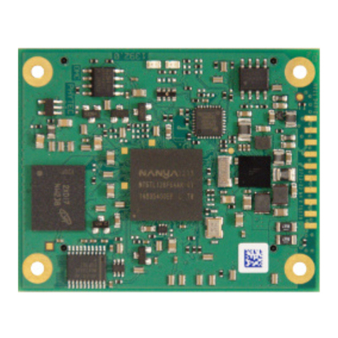
Solectron Force Computers Alpha VME 5/352 User manual

Force Computers, Inc.
San Jose, California
Alpha VME 5/352 and 5/480
Single-Board Computers
Installation Guide
Order Number: EK–VME54–IG. C01
This guide explains how to install Alpha VME 5/352 and 5/480 single-board
computers (SBCs).
Revision/Update Information: ThisguidesupersedestheDIGITAL
Alpha VME 5/352 and 5/480 Single-
Board Computers Installation
Guide, EK–VME54–IG. B01.

June 2000
The information in this publication is subject to change without notice. Force Computers Inc. reserves the right to make
changes without notice to this, or any of its products, to improve reliability, performance, or design.
FORCE COMPUTERS, INC. SHALL NOT BE LIABLE FOR TECHNICAL OR EDITORIAL ERRORS OR
OMISSIONS CONTAINED HEREIN, NOR FOR INDIRECT, SPECIAL, INCIDENTAL, OR CONSEQUENTIAL
DAMAGES RESULTING FROM THE FURNINSHING, PERFORMANCE, OR USE OF THIS MATERIAL. THIS
INFORMATION IS PROVIDED “AS IS” AND FORCE COMPUTERS, INC. EXPRESSLY DISCLAIMS ANY AND
ALL WARRANTIES, EXPRESS, IMPLIED, STATUTORY, OR OTHERWISE, INCLUDING WITHOUT
LIMITATION, ANY EXPRESS, STATUTORY, OR IMPLIED WARRANTY OF MERCHANTABILITY, FITNESS
FOR A PARTICULAR PURPOSE, OR NON-INFRINGEMENT.
This publication contains information protected by copyright. This publication shall not be reproduced, transmitted, or
stored in a retrieval system, nor its contents used for any purpose, without the prior written consent of Force Computers,
Inc.
Force Computers, Inc. assumes no responsibility for the use of any circuitry other than circuitry that is part of a product of
Force Computers, Inc. Force Computers, Inc. does not convey to the purchaser of the product described herein any license
under the patent rights of Force Computers, Inc. nor the rights of others.
Copyright © 2000 by Force Computers, Inc. Certain portions © 1997 Compaq Computer Corporation. All rights reserved.
The Force logo is a trademark of Force Computers, Inc.
DALLAS is a registered trademark of Dallas Systems Corporation.
COMPAQ and the Compaq logo Registered in U.S. Patent and Trademark Office. Tru64 is a trademark of Compaq Informa-
tion Technologies Group, L.P.
UNIX and The Open Group are trademarks of The Open Group.
IBM is a registered trademark of International Business Machines Corporation.
Intel is a trademark of Intel Corporation.
NCR is a registered trademark of NCR Corporation.
VIC64 is a trademark of Cypress Semiconductor Corporation.
VxWorks is a registered trademark of Wind River Systems, Inc.
Other product names mentioned herein may be trademarks and/or registered trademarks of their respective companies.

FCC Notice:
This equipment has been tested and found to comply with the limits for a Class A digital device, pursuant to Part 15 of the
FCC Rules. These limits are designed to provide reasonable protection against harmful interference when the equipment is
operated in a commercial environment. This equipment generates, uses, and can radiate radio frequency energy and, if not
installed and used in accordance with the instruction manual, may cause harmful interference to radio communications.
Operation of this equipment in a residential area is likely to cause harmful interference, in which case the user will be
required to correct the interference at his own expense.
Warning!
This is a Class A product. In a domestic environment this product may cause radio interference in which case the user may
be required to take adequate measures.
Achtung!
Dieses ist ein Gerät der Funkstörgrenzwertklasse A. In Wohnbereichen können bei Betrieb dieses Gerätes
Rundfunkstörungenauftreten, in welchen Fällen der Benutzer für entsprechende Gegenmaßnahmen verantwortlich ist.
Attention!
Ceci est un produit de Classe A. Dans un environment domestique, ce produit risque de créer des interférences
radioélectriques, il appartiendra alors à l'utilisateur de prendre les mesures spécifiques appropriées.
Canadian EMC Notice:
“This Class [A] Digital apparatus meets all requirements of the Canadian Interference-Causing Equipment Regulations.”
“Cet appareil numerique de la class [A] respecte toutes les exigences du Reglement sur le materiel broilleur du Canada.”
Note: Shielded data cables must be used to interconnect this equipment to comply with the FCC limits for a Class B
device.


Contents
v
Preface
1 Preparing for the Installation
Unpacking Kit Contents . . . . . . . . . . . . . . . . . . . . . . . . . . . . . . . . . . . . . . . . . . . . . . . . . . . . 1-1
Verifying Kit Contents . . . . . . . . . . . . . . . . . . . . . . . . . . . . . . . . . . . . . . . . . . . . . . . . . . . . .1-1
Checking for Ordered Options . . . . . . . . . . . . . . . . . . . . . . . . . . . . . . . . . . . . . . . . . . . . . . . 1-3
Getting Familiar with Your SBC’s Major Components . . . . . . . . . . . . . . . . . . . . . . . . . . . . 1-3
CPU Module. . . . . . . . . . . . . . . . . . . . . . . . . . . . . . . . . . . . . . . . . . . . . . . . . . . . . . . . . . . 1-4
I/O Module . . . . . . . . . . . . . . . . . . . . . . . . . . . . . . . . . . . . . . . . . . . . . . . . . . . . . . . . . . . . 1-5
CPU and I/O Assembly Controls and Indicators . . . . . . . . . . . . . . . . . . . . . . . . . . . . . . . 1-6
Memory Modules . . . . . . . . . . . . . . . . . . . . . . . . . . . . . . . . . . . . . . . . . . . . . . . . . . . . . . . 1-7
Primary Breakout Module . . . . . . . . . . . . . . . . . . . . . . . . . . . . . . . . . . . . . . . . . . . . . . . . 1-8
Secondary Breakout Module . . . . . . . . . . . . . . . . . . . . . . . . . . . . . . . . . . . . . . . . . . . . . . 1-9
PMC I/O Companion Card. . . . . . . . . . . . . . . . . . . . . . . . . . . . . . . . . . . . . . . . . . . . . . . . 1-10
Understanding Power Requirements. . . . . . . . . . . . . . . . . . . . . . . . . . . . . . . . . . . . . . . . . . . 1-12
Identifying the VME Chassis and Backplane Slots . . . . . . . . . . . . . . . . . . . . . . . . . . . . . . . 1-13
VME Chassis Requirements. . . . . . . . . . . . . . . . . . . . . . . . . . . . . . . . . . . . . . . . . . . . . . . 1-13
Backplane Considerations . . . . . . . . . . . . . . . . . . . . . . . . . . . . . . . . . . . . . . . . . . . . . . . . 1-13
2 Installing the SBC
Installation at a Glance . . . . . . . . . . . . . . . . . . . . . . . . . . . . . . . . . . . . . . . . . . . . . . . . . . . . . 2-2
Setting Configuration Switches on the I/O Module . . . . . . . . . . . . . . . . . . . . . . . . . . . . . . . 2-3
Installing the Memory Modules . . . . . . . . . . . . . . . . . . . . . . . . . . . . . . . . . . . . . . . . . . . . . . 2-5
Installing a PMC I/O Companion Card and Options . . . . . . . . . . . . . . . . . . . . . . . . . . . . . . 2-6
Installing the CPU and I/O Modules in the VME Chassis . . . . . . . . . . . . . . . . . . . . . . . . . . 2-7
Setting Up and Installing the Primary Breakout Module . . . . . . . . . . . . . . . . . . . . . . . . . . . 2-9
Setting Up and Installing the Secondary Breakout Module . . . . . . . . . . . . . . . . . . . . . . . . . 2-12
Connecting Network and Serial-Line Cables . . . . . . . . . . . . . . . . . . . . . . . . . . . . . . . . . . . . 2-13
Inserting Blank Panels. . . . . . . . . . . . . . . . . . . . . . . . . . . . . . . . . . . . . . . . . . . . . . . . . . . . . .2-14
3 Finishing the Installation
Powering on the SBC . . . . . . . . . . . . . . . . . . . . . . . . . . . . . . . . . . . . . . . . . . . . . . . . . . . . . . 3-1
Monitoring the Power-On Self-Test Diagnostics . . . . . . . . . . . . . . . . . . . . . . . . . . . . . . . . . 3-1
Configuring the System. . . . . . . . . . . . . . . . . . . . . . . . . . . . . . . . . . . . . . . . . . . . . . . . . . . . . 3-3
Booting an Operating System . . . . . . . . . . . . . . . . . . . . . . . . . . . . . . . . . . . . . . . . . . . . . . . . 3-4
A Cables and Connectors

vi
B Troubleshooting
SROM Diagnostics. . . . . . . . . . . . . . . . . . . . . . . . . . . . . . . . . . . . . . . . . . . . . . . . . . . . . . . . B-1
Flash ROM Diagnostics . . . . . . . . . . . . . . . . . . . . . . . . . . . . . . . . . . . . . . . . . . . . . . . . . . . . B-1
Troubleshooting Systems that Include a PMC I/O Companion Card . . . . . . . . . . . . . . . . . B-2
Operating System and Application Use of the Dot Matrix Display. . . . . . . . . . . . . . . . . . . B-2
Troubleshooting Your SBC . . . . . . . . . . . . . . . . . . . . . . . . . . . . . . . . . . . . . . . . . . . . . . . . . B-2
Figures
1–1 CPU Module Layout. . . . . . . . . . . . . . . . . . . . . . . . . . . . . . . . . . . . . . . . . . . . 1-4
1–2 I/O Module Layout . . . . . . . . . . . . . . . . . . . . . . . . . . . . . . . . . . . . . . . . . . . . . 1-5
1–3 Controls and Indicators. . . . . . . . . . . . . . . . . . . . . . . . . . . . . . . . . . . . . . . . . . 1-6
1–4 Memory Module . . . . . . . . . . . . . . . . . . . . . . . . . . . . . . . . . . . . . . . . . . . . . . . 1-7
1–5 Primary Breakout Module . . . . . . . . . . . . . . . . . . . . . . . . . . . . . . . . . . . . . . . 1-9
1–6 Secondary Breakout Module . . . . . . . . . . . . . . . . . . . . . . . . . . . . . . . . . . . . . 1-10
1–7 PMC I/O Companion Card Layout. . . . . . . . . . . . . . . . . . . . . . . . . . . . . . . . . 1-11
1–8 Required Air Flow Relative to Ambient Temperature . . . . . . . . . . . . . . . . . . 1-13
1–9 Active Buffer Backplane . . . . . . . . . . . . . . . . . . . . . . . . . . . . . . . . . . . . . . . . 1-15
1–10 Active OR Backplane . . . . . . . . . . . . . . . . . . . . . . . . . . . . . . . . . . . . . . . . . . . 1-15
2–1 Installation at a Glance . . . . . . . . . . . . . . . . . . . . . . . . . . . . . . . . . . . . . . . . . . 2-2
2–2 Setting I/O Module Configuration Switches . . . . . . . . . . . . . . . . . . . . . . . . . 2-3
2–3 Installing Memory Modules . . . . . . . . . . . . . . . . . . . . . . . . . . . . . . . . . . . . . . 2-5
2–4 Setting PMC I/O Companion Card Jumpers. . . . . . . . . . . . . . . . . . . . . . . . . . 2-6
2–5 Connecting the PMC I/O Companion Card to the I/O Module . . . . . . . . . . . 2-7
2–6 Installing a 2-Slot SBC Module Assembly. . . . . . . . . . . . . . . . . . . . . . . . . . . 2-8
2–7 Installing a 3-Slot SBC Module Assembly. . . . . . . . . . . . . . . . . . . . . . . . . . . 2-8
2–8 Identifying the Primary Breakout Module . . . . . . . . . . . . . . . . . . . . . . . . . . . 2-9
2–9 Setting the Primary Breakout Module Jumpers . . . . . . . . . . . . . . . . . . . . . . . 2-10
2–10 Connecting the SCSI Cable to the Primary Breakout Module . . . . . . . . . . . . 2-11
2–11 Installing the Primary Breakout Module . . . . . . . . . . . . . . . . . . . . . . . . . . . . 2-12
2–12 Setting the Secondary Breakout Module Jumpers . . . . . . . . . . . . . . . . . . . . . 2-13
2–13 Connecting the Secondary and Primary Breakout Modules. . . . . . . . . . . . . . 2-13
2–14 Connecting Network and Serial-Line Cables . . . . . . . . . . . . . . . . . . . . . . . . . 2-14
Tables
1–1 Alpha VME 5/352 and 5/480 SBC Kit Contents . . . . . . . . . . . . . . . . . . . . . . 1-2
1–2 Alpha VME 5/352 and 5/480 SBC Options . . . . . . . . . . . . . . . . . . . . . . . . . . 1-3
1–3 Controls and Indicators. . . . . . . . . . . . . . . . . . . . . . . . . . . . . . . . . . . . . . . . . . 1-6
1–4 Valid DIMM Combinations . . . . . . . . . . . . . . . . . . . . . . . . . . . . . . . . . . . . . 1-8
1–5 Input Power Requirements . . . . . . . . . . . . . . . . . . . . . . . . . . . . . . . . . . . . . . . 1-12
2–1 I/O Module Configuration Switches. . . . . . . . . . . . . . . . . . . . . . . . . . . . . . . . 2-3
2–2 Switch Settings for Modules in Slots 1 and 2 (System Controller). . . . . . . . 2-4
2–3 Switch Settings for Modules in Slots Other Than Slots 1 and 2. . . . . . . . . . . 2-4
3–1 SROM Initialization and Console Tests . . . . . . . . . . . . . . . . . . . . . . . . . . . . . 3-1
A–1 Cables and Connectors . . . . . . . . . . . . . . . . . . . . . . . . . . . . . . . . . . . . . . . . . . A-1
B–1 Troubleshooting Your SBC . . . . . . . . . . . . . . . . . . . . . . . . . . . . . . . . . . . . . B-2

vii
Preface
Purpose of this Guide
This guide explains how to install and troubleshoot your Alpha VME 5/352 or
5/480 SBC.
Intended Audience
This guide is for system integrators, field and manufacturing technicians, and sup-
port specialists who need to install the SBCs and diagnose problems. The guide
assumes that readers have prerequisite knowledge and experience with the follow-
ing:
•CPU modules and SBCs and how to assemble and disassemble them
•VMEbus design and specifications
Structure of this Guide
This guide consists of three chapters and two appendixes organized as follows:
•Chapter 1, Preparing for the Installation, explains how to unpack and verify
your kit contents and check for ordered options. It also helps you get
acquainted with the SBC’s major components.
•Chapter 2, Installing the SBC, provides step-by-step instructions on how to
install the SBC.
•Chapter 3, Finishing the Installation, explains how to power on the SBC,
monitor diagnostics, configure the system, and boot an operating system.
•Appendix A, Cables and Connectors, lists cables and connectors you may
need for the installation.
•Appendix B, Troubleshooting, introduces SROM and flash ROM diagnostics.
This appendix also provides tips on troubleshooting your SBC and systems
that include a PMC I/O companion card.
Conventions
This section defines terminology, abbreviations, and other conventions used in
this guide.

viii
Abbreviations
•Binary multiples
The abbreviations K, M, and G (kilo, mega, and giga) represent binary
multiples and have the following values:
For example:
Addresses
Unless otherwise noted, addresses and offsets are hexadecimal values.
Bit Notation
Multiple-bit fields can include contiguous and noncontiguous bits contained in
angle brackets (< >). Multiple contiguous bits are indicated by a pair of numbers
separated by a colon ( : ). For example, <9:7,5,2:0> specifies bits 9, 8, 7, 5, 2, 1,
and 0. Similarly, single bits are frequently indicated with angle brackets. For
example, <27> specifies bit 27.
Caution
Cautions indicate potential damage to equipment or loss of data.
Keyboard Keys
The following keyboard key conventions are used throughout this guide.
Abbreviation Binary Multiple
K2
10 (1024)
M2
20 (1,048,576)
G2
30 (1,073,741,824)
2 KB = 2 kilobytes = 2 x 210 bytes
4 MB = 4 megabytes = 4 x 220 bytes
8 GB = 8 gigabytes = 8 x 230 bytes
Convention Example
Control key sequences are represented as Ctrl/
x
.
Press Ctrl while you simultaneously press the
x
key. Ctrl/C
In plain text, key names match the name on the actual
key. Return key
In tables, key names match the name of the actual key and appear in
square brackets ([ ]).. [Return]

ix
Names and Symbols
The following table lists typographical conventions used for names of various
items throughout this guide.
Note
Notes emphasize particularly important information.
Numbering
Numbers are decimal or hexadecimal unless otherwise indicated. The prefix 0x
indicates a hexadecimal number. For example, 19 is decimal, but 0x19 and 0x19A
are hexadecimal (see also Addresses). Otherwise, the base is indicated by a sub-
script; for example, 1002is a binary number.
For More Information
For more information, refer to the following:
•Your supplier
•A Force field applications engineer
•The Force Computers web site at http://www.forcecomputers.com.
Items Example
Commands boot command
Command arguments address argument
Command options -sb option
Environment variables AUTO_ACTION
Environment variable values HALT
Files and pathnames /usr/foo/bar
Pins LIRQ pin
Variables
n
,
x
,
mydev

x
•The following Alpha VME 5/352 and 5/480 SBC documentation, which is
available on the Force Computers web site:
•Documentation available from the Compaq Computer Corporation web site :
Tru64 UNIX online documentation and reference pages, including the Guide
to Realtime Programing and the System Configuration Supplement: OEM
Platforms, at
http://www.unix.digital.com/faqs/publications/pub_page/doc_list.html
Device driver online books, technical updates, and related documentation at
http://www.unix.digital.com/faqs/publications/pub_page/devdoc_list.html
•The following specifications, which are available through the indicated ven-
dor or organization:
Document Order Number Description
Alpha VME 5/352 and 5/480
Board Computer Family Data
Sheet
Describes the Alpha 5/352 and 5/480 SBCs, high-
lighting product features and specifications.
Alpha VME 5/352 and 5/480 Sin-
gle Board Computers Information
Sheet
EK–VME54–CL Highlights important product information and
explains how to acquire the Alpha VME 5/352 and
5/480 Single Board Computers User Manual and
Alpha VME 5/352 and 5/480 Single Board Comput-
ers Technical Reference.
Alpha VME 5/352 and 5/480 Sin-
gle Board Computers Installation
Guide (this document)
EK–VME54–IG Explains how to install your Alpha VME 5/352 or
5/480 SBC. Use this guide if you need to adjust
jumper settings or remove and reinstall field
replaceable units (FRUs).
Alpha VME 5/352 and 5/480 Sin-
gle Board Computers User Man-
ual
EK–VME54–UM Introduces the product by discussing product speci-
fications and requirements and describing the mod-
ule and functional components. This manual also
explains how to use the console firmware and dis-
cusses diagnostics and troubleshooting.
Alpha VME 5/352 and 5/480 Sin-
gle Board Computers Technical
Reference
EK–VME54–TM This manual discusses system address mapping, the
VME interface, system registers, and system inter-
rupts.
Document Vendor or Organization
CY7C9640 Specification Cypress Semiconductor Corp.
Intel 82378ZB PCI-ISA Bridge Chip
Specification Intel Corp.
PCI Local Bus Specification Rev 2.1 PCI Special Interest Group
Super I/O FDC37C6656T Specification Standard Microsystems Corp.
Symbios 53C810 SCSI Controller Spec-
ification Symbios
TOY clock DS1386 Specification Dallas Semiconductor
VIC64 Specification Cypress Semiconductor Corp.

Preparing for the Installation 1–1
1
Preparing for the Installation
This chapter explains how to prepare for a Alpha VME 5/352 or 5/480 SBC instal-
lation. The chapter explains:
•How to unpack kit contents, Section 1.1
•How to verify kit contents, Section 1.2
•How to check for ordered options, Section 1.3
•Your SBC’s major kit components, Section 1.4
•Power requirements, Section 1.5
•How to identify a VME chassis and required backplane slots, Section 1.6
1.1 Unpacking Kit Contents
Start preparing for your installation by unpacking your Alpha VME 5/352 or
5/480 SBC kit.
1. Verify that the order numbers on the labels on your kit carton match the num-
bers for the product you ordered. If the order numbers do not match, contact
your Customer Support Center in your geography.
2. Remove the top layer of packing foam.
3. Remove all items from the kit carton.
4. Locate and put on the antistatic wrist strap.
5. Clip the wire attached to the wrist strap to the frame of your VME chassis.
6. Remove the hardware components from the conductive plastic bags in which
they were packaged and place the components on the bags.
Note
Store the original packing material in case a factory return is necessary.
1.2 Verifying Kit Contents
Table 1–1 lists Alpha VME 5/352 and 5/480 SBC kit contents. Verify that the
material you unpacked matches the contents listed in the table. Your kit may also
include software or software licenses, depending on what you ordered.

1–2 Preparing for the Installation
If you ordered memory for your Alpha VME 5/352 or 5/480 SBC, your kit will
also include that memory. Four memory connectors on the CPU module constitute
a single bank and require that all DIMMs be of the same size, speed, and architec-
ture. Each memory module kit consists of two DIMMs. You have the option of
using either one or two of a given memory module kit listed in Table 1–1.
1Installation is necessary for the operation of an Alpha VME 5/352 or 5/480 SBC.
2Optional memory, which is ordered separately, will be included in your kit or packed separately, depending on how the
memory was purchased.
Table 1–1 Alpha VME 5/352 and 5/480 SBC Kit Contents
Part Part Name Part Number
Cover Letter EK–VME54-CL
Warranty and Parts Information EK–VME54-WI
Installation Guide EK–VME54-IG
Antistatic wrist strap 12–36175–01
CPU and I/O assembly 70–3–3394–01 (5/480)
70–3–3394–02 (5/352)
Primary breakout module (type 1)154–24663–01
Secondary breakout module (type 2) 54–24729–01
Memory DIMMs2
2 X 8 MB
2 X 16 MB
2 X 32 MB
2 X 64 MB
2 X 128 MB
EBXMA–DC
EBXMA–EC
EBXMA–FC
EBXMA–GC
EBXMA–HC

Preparing for the Installation 1–3
1.3 Checking for Ordered Options
In addition to the base product kit, you may need other hardware options, depend-
ing on how you plan to use the Alpha VME 5/352 or 5/480 SBC. You need to
order these options separately.
Other hardware options include a PMC I/O companion card for expanding the I/O
capabilities of your SBC.
You may need to attach a local disk. To do this you need to use and properly ter-
minate a 50-pin IDC SCSI cable. The exact cable requirements depend upon the
enclosure, disk mounting, and so forth. A PC “internal SCSI” cable will work if
you are connecting to an internal disk and the cable has a SCSI terminator, or if
the last disk (or other SCSI device) has an internal terminator.
To attach a printer to the parallel port of the secondary breakout module (54–
24729–01), you need to use a standard parallel port printer cable that has a 26-pin
IDC connector on one end.
Table 1–2 lists Alpha VME 5/352 and 5/480 SBC options. Check that you
received the options you ordered.
1Also available on the worldwide web at http://www.forcecomputers.com.
1.4 Getting Familiar with Your SBC’s Major Components
This section helps you get familiar with the major components of an Alpha VME
5/352 or 5/480 SBC. Sections 1.4.1 through 1.4.7 describe the:
•CPU module, Section 1.4.1
•I/O module, Section 1.4.2
Table 1–2 Alpha VME 5/352 and 5/480 SBC Options
Part Name Part Number
Hardware Options
PMC I/O companion card EBV1P–AA
Serial-line cable for console and auxiliary terminals
2 ft. cable
6 ft. cable
10 ft. cable
25 ft. cable
50 ft. cable
100 ft. cable
BC16E–06
BC16E–05
BC16E–02
BC16E–03
BC16E–04
BC16E–11
IEEE 802.3 twisted-pair transceiver to ThinWire DETTR–AA
IEEE 802.3 twisted-pair transceiver to twisted-pair DETTR–BB
10BASET loopback connector H4082–AA
Documentation1
User Manual EK–VME54–UM
Technical Reference EK–VME54–TM

1–4 Preparing for the Installation
•CPU and I/O assembly controls and indicators, Section 1.4.3
•Memory modules, Section 1.4.4
•Primary breakout module, Section 1.4.5
•Secondary breakout module, Section 1.4.6
•PMC I/O companion card, Section 1.4.7
1.4.1 CPU Module
The CPU module is the compute engine of Alpha VME 5/352 and 5/480 SBCs.
Figure 1–1 shows the layout and primary components.
Figure 1–1 CPU Module Layout
The numeric callouts in the figure identify the following key components:
1P1 VMEbus connector
2P2 VMEbus connector
364-bit PCI connector (not used)
4J11 bus grant pass-through jumper
5Connectors for memory DIMMs 2 and 3
6Connectors for memory DIMMs 0 and 1
7Power and VME slave activity/watchdog timeout LED
8Status display
9I/O module connector
10 SROM
ML013781
5
9
78
3
1 2
10
6
4

Preparing for the Installation 1–5
1.4.2 I/O Module
The I/O module is a required second tier module that handles all I/O activity for
the Alpha VME 5/352 and 5/480 SBCs. This module plugs into the I/O module
connector on the CPU module.
Note
The I/O module is attached to the CPU module when you receive it. Dis-
assemble the CPU and I/O assembly only if you need to replace the
SROM.
Figure 1–2 shows the layout and primary components.
Figure 1–2 I/O Module Layout
The numeric callouts in the figure identify the following key components:
1P1 VMEbus connector
2Connector to CPU module (on the back of the I/O module)
3Debug jumper (for use with Serial ROM Mini-Console only)
4P2 VMEbus connector
5Configuration switchpack
6Caterpillar insulation strip
7PMC I/O companion card connector
8Nonvolatile RAM/time-of-year (TOY) clock
9Auxiliary serial port
ML013782
9101112
7
8
51 42 3
6

1–6 Preparing for the Installation
10 Console serial port
11 Reset/Halt switch
12 Twisted-pair Ethernet connector
1.4.3 CPU and I/O Assembly Controls and Indicators
The CPU and I/O modules are delivered as a single assembly. The modules are
attached and share a single front panel. Figure 1–3 shows the controls and indica-
tors on that front panel and Table 1–3 describes their functions.
Figure 1–3 Controls and Indicators
1See your operating system documentation for information on how to recover from reset and halt
operations.
Table 1–3 Controls and Indicators
Callout Control or Indicator Description
1Reset/Halt switch A switch that resets the SBC when pressed in the
Reset (up) direction and halts the operating system
when pressed in the Halt (down) direction. A reset
operation starts SROM execution the same way as
when you power on the system. When you use the
Halt switch, the SBC enters console mode.
Caution: Keep in mind that reset and halt opera-
tions can cause loss of data.1
2Status display A display that shows which test is running during
power-on self-test (POST) diagnostics. When the
POST diagnostics are complete, the display is under
control of the operating system or an application
program.
3VME Slave Activ-
ity/Watchdog Time-
out LED
An amber LED with two functions. The LED flashes
when the SBC is accessed as a slave by another
device on the VMEbus. The LED lights continu-
ously when the watchdog timer has timed out.
Note: The LED can appear to light continuously
when the module is receiving slave accesses. Since
the LED glows for 1/3 of a second each time it
flashes, three slave accesses per second could make
the LED light continuously.
4Power LED A green LED that is lit when the power is on.
1
234 ML013262

Preparing for the Installation 1–7
1.4.4 Memory Modules
The Alpha VME 5/352 and 5/480 SBCs support memory configurations that
range from 16 to 512 MB of dynamic random access memory (DRAM). This
memory is accessible from the CPU, PCI bus, and VMEbus.
You can plug either two or four dual integrated memory modules (DIMMs), rang-
ing from 8 MB to 128 MB, into the memory connectors on the CPU module. Fig-
ure 1–4 shows a typical memory module.
Figure 1–4 Memory Module
The number of DIMMs you use determines the memory bus bandwidth, and con-
sequently the overall speed of data write and read operations to and from memory.
Force Computers recommends that you use four DIMMs to achieve maximum
performance. No jumper changes are required. The system automatically config-
ures memory based on the DIMMs you install. The following table shows the
width of the memory bus and its performance when you use two and four DIMMs:
Error correction code (ECC) is provided for single-bit errors and error detection is
provided for double-bit errors. For details on how the operating system reports
and handles ECC errors, see your operating system documentation.
In addition to the requirement of using either two or four DIMMs, all DIMMs you
use must be identical in size (number of MB), speed, and architecture (EDO).
Note
Memory DIMMs for the Alpha VME 5/352 and 5/480 are supplied in
pairs. To ensure proper operation of your SBC, you must install the
DIMMs as supplied pairs in memory connectors 0 and 1 or 2 and 3. If you
choose to use only two DIMMs, you must populate memory connectors 0
and 1.
Number of DIMMs Bus Width Memory Bandwidth
2 128 bits 210 MB/s
4 256 bits 355 MB/s
ML013783

1–8 Preparing for the Installation
Table 1–4 shows valid DIMM combinations.
1.4.5 Primary Breakout Module
The primary breakout module is a required module that plugs into your VMEbus
backplane behind the slots occupied by your Alpha VME 5/352 or 5/480 SBC
CPU and I/O modules. This breakout module supplies additional power to the
CPU module by way of the VMEbus P2 connector and provides:
•A connector for attaching a SCSI bus
•Additional P2 options, such as the secondary breakout module
•SCSI termination control
•A connection for and control of a watchdog timeout signal
•A connector to Alpha VME external timing signals
Figure 1–5 shows the primary breakout module.
Table 1–4 Valid DIMM Combinations
Memory Size
(MB) DIMM 0
(MB) DIMM 1
(MB) DIMM 2
(MB) DIMM 3
(MB)
16 8 8
328888
32 16 16
64 16 16 16 16
64 32 32
128 32 32 32 32
128 64 64
256 64 64 64 64
256 128 128
512 128 128 128 128

Preparing for the Installation 1–9
Figure 1–5 Primary Breakout Module
The numeric callouts in the figure identify the following key components:
1SCSI termination and watchdog reset signal jumpers
2Connector for the secondary breakout module or an external monitoring
device
3SCSI cable connector
A reset input signal on pin C10 of the primary breakout module’s VMEbus P2
connector is available for resetting the SBC. This signal is low during normal
operation and high during a watchdog timer reset in parallel with the Reset switch
on the SBC’s front panel. Because pin C10 is a nonbuffered input pin, you should
use shielded wiring to apply the reset input signal.
Caution
You must use the primary breakout module included in your Alpha VME
5/352 or 5/480 SBC hardware kit. Applying power to an Alpha VME
5/352 or 5/480 SBC WITHOUT that primary breakout module in place,
or WITH the breakout module included with the AXPvme 160, 166, or
230 (part number 54-22605-01) in place, may damage your backplane,
the Alpha VME 5/352 or 5/480 SBC, or both.
1.4.6 Secondary Breakout Module
The secondary breakout module is an optional module that connects to the pri-
mary breakout module. Connectors on the secondary breakout module include a
PS/2 keyboard and mouse Y-cable connector and a parallel port connector. The
primary use of this module is to add a serial-line (keyboard and mouse) connector
and parallel port to the rear of the VME chassis.
Figure 1–6 shows the secondary breakout module.
ML013784
2
3
1

1–10 Preparing for the Installation
Figure 1–6 Secondary Breakout Module
The numeric callouts in the figure identify the following key components:
1PS/2 keyboard and mouse connector
2PS/2 keyboard and mouse Y-cable (supplied in PMC I/O companion card kits,
EBV1P)
3Keyboard and mouse jumper
4Parallel port
Note
The Alpha VME 5/352 and 5/480 SBCs support a PS/2-type 101-compat-
ible keyboard and mouse.
1.4.7 PMC I/O Companion Card
The PMC I/O companion card is an optional third tier module that plugs into a
connector on the I/O module. Using the PMC I/O companion card, you can
expand your SBC’s I/O capabilities by adding interfaces, such as a second Ether-
net interface or a graphics card. Primary components on the companion card
include connectors for two PMC options, a PCI-to-PCI bridge chip, keyboard and
mouse connectors, two VMEbus connectors, and a VMEbus P2 signal connector.
The VMEbus P2 signal connector provides a way of sending I/O signals from a
PMC option to a device attached to the VMEbus P2 connector instead of to the
front panel of the PMC option card.
To use the PMC I/O companion card, you must have three adjacent slots available
in your VME chassis.
Figure 1–7 shows the layout of the card.
ML013785
1
4
3
2
This manual suits for next models
1
Table of contents
Other Solectron Single Board Computer manuals


