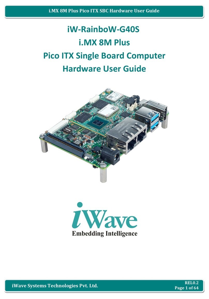
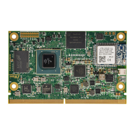
iWave iW-RainboW-G25M Installation manual

REL0.1
Page 1 of 52
Snapdragon 820 SMARC SOM Hardware User Guide
iWave Systems Technologies Pvt. Ltd.
iW-RainboW-G25M
Snapdragon 820 SMARC SOM
Hardware User Guide
DRAFT VERSION SUBJECT TO CHANGE

REL0.1
Page 2 of 52
Snapdragon 820 SMARC SOM Hardware User Guide
iWave Systems Technologies Pvt. Ltd.
Document Revision History
Document Number
iW-PRFDZ-UM-01-R1.0-REL0.1-Hardware
Revision
Date
Description
0.1
20th Sep 2017
Initial Draft Version
PROPRIETARY NOTICE: This document contains proprietary material for the sole use of the intended recipient(s). Do
not read this document if you are not the intended recipient. Any review, use, distribution or disclosure by others is
strictly prohibited. If you are not the intended recipient (or authorized to receive for the recipient), you are hereby
notified that any disclosure, copying distribution or use of any of the information contained within this document is
STRICTLY PROHIBITED. Thank you. “iWave Systems Tech. Pvt. Ltd.”

REL0.1
Page 3 of 52
Snapdragon 820 SMARC SOM Hardware User Guide
iWave Systems Technologies Pvt. Ltd.
Disclaimer
iWave Systems reserves the right to change details in this publication including but not limited to any Product
specification without notice.
No warranty of accuracy is given concerning the contents of the information contained in this publication. To the
extent permitted by law no liability (including liability to any person by reason of negligence) will be accepted by iWave
Systems, its subsidiaries or employees for any direct or indirect loss or damage caused by omissions from or
inaccuracies in this document.
CPU and other major components used in this product may have several silicon errata associated with it. Under no
circumstances, iWave Systems shall be liable for the silicon errata and associated issues.
Trademarks
All registered trademarks, product names mentioned in this publication are the property of their respective owners
and used for identification purposes only.
Certification
iWave Systems Technologies Pvt. Ltd. is an ISO 9001:2015 Certified Company.
Warranty & RMA
Warranty support for Hardware: 1 Year from iWave or iWave's EMS partner.
For warranty terms, go through the below web link,
http://www.iwavesystems.com/support/warranty.html
For Return Merchandise Authorization (RMA), go through the below web link,
http://www.iwavesystems.com/support/rma.html
Technical Support
iWave Systems technical support team is committed to provide the best possible support for our customers so that
our Hardware and Software can be easily migrated and used.
For assistance, contact our Technical Support team at,
Email : support.ip@iwavesystems.com
Website : www.iwavesystems.com
Address : iWave Systems Technologies Pvt. Ltd.
# 7/B, 29th Main, BTM Layout 2nd Stage,
Bangalore, Karnataka,
India –560076

REL0.1
Page 4 of 52
Snapdragon 820 SMARC SOM Hardware User Guide
iWave Systems Technologies Pvt. Ltd.
Table of Contents
1. INTRODUCTION ..................................................................................................................................................7
1.1 Purpose .......................................................................................................................................................7
1.2 Snapdrgon 820 SMARC SOM Overview ........................................................................................................7
1.3 List of Acronyms ..........................................................................................................................................7
1.4 Terminlogy Description................................................................................................................................9
1.5 References...................................................................................................................................................9
1.6 Important Note..........................................................................................................................................10
2. ARCHITECTURE AND DESIGN ............................................................................................................................11
2.1 Snapdragon 820 SMARC SOM Block Diagram.............................................................................................11
2.2 Snapdragon 820 SMARC SOM Features......................................................................................................12
2.3 Qualcomm APQ8096 CPU ..........................................................................................................................14
2.4 Power Management..................................................................................................................................15
2.4.1 PM8996 PMIC........................................................................................................................................15
2.4.2 PMI8996 Battery Charging IC .................................................................................................................15
2.5 Memory.....................................................................................................................................................15
2.5.1 LPDDR4 RAM .........................................................................................................................................15
2.5.2 eMMC Flash...........................................................................................................................................15
2.5.3 Micro SD Connector slot.........................................................................................................................16
2.6 Network & Communiation.........................................................................................................................17
2.6.1 Wi-Fi and Bluetooth Interface ................................................................................................................17
2.6.2 GPS Interface .........................................................................................................................................18
2.7 SMARC PCB Edge Connector ......................................................................................................................19
2.7.1 Gigabit Ethernet ....................................................................................................................................20
2.7.2 SD Interface ...........................................................................................................................................20
2.7.3 Audio Interface ......................................................................................................................................20
2.7.4 SPI Interface...........................................................................................................................................20
2.7.5 USB Interface.........................................................................................................................................21
2.7.6 PCIe Interface ........................................................................................................................................21
2.7.7 HDMI Interface ......................................................................................................................................21
2.7.8 MIPI DSI Display Interface......................................................................................................................21
2.7.9 MIPI CSI Camera ....................................................................................................................................22
2.7.10 Data UART.............................................................................................................................................22
2.7.11 SMARC GPIOs ........................................................................................................................................22
2.7.12 Power control & Management signals....................................................................................................22
2.8 Expansion Connector .................................................................................................................................37
2.9 Optional Features ......................................................................................................................................43
2.9.1 JTAG Header ..........................................................................................................................................43
2.9.2 Debug UART Header ..............................................................................................................................44
2.9.3 Battery Connector..................................................................................................................................44
2.9.4 Audio In/Out Jack...................................................................................................................................45
2.9.5 UFS - Universal Flash Storage.................................................................................................................45

REL0.1
Page 5 of 52
Snapdragon 820 SMARC SOM Hardware User Guide
iWave Systems Technologies Pvt. Ltd.
3. TECHNICAL SPECIFICATION...............................................................................................................................46
3.1 Electrical Characteristics ............................................................................................................................46
3.1.1 Power Input Sequencing.........................................................................................................................47
3.1.2 Power Consumption...............................................................................................................................47
3.2 Environmental Characteristics ...................................................................................................................48
3.2.1 Environmental Specification...................................................................................................................48
3.2.2 RoHS Compliance...................................................................................................................................48
3.2.3 Electrostatic Discharge...........................................................................................................................48
3.3 Mechanical Characteristics ........................................................................................................................49
3.3.1 Snapdragon 820 SMARC SOM Mechanical Dimensions...........................................................................49
4. ORDERING INFORMATION................................................................................................................................50
5. APPENDIX .........................................................................................................................................................51
5.1 Snapdragon 820 SMARC SOM Development Platform................................................................................51

REL0.1
Page 6 of 52
Snapdragon 820 SMARC SOM Hardware User Guide
iWave Systems Technologies Pvt. Ltd.
List of Figures
Figure 1: Snapdragon 820 SMARC SOM Block Diagram..............................................................................................11
Figure 2: Micro SD Connector....................................................................................................................................16
Figure 3: WLAN/BT Antenna Connector ....................................................................................................................17
Figure 4: GPS Antenna Connector .............................................................................................................................18
Figure 5: SMARC Edge Connector..............................................................................................................................19
Figure 6: SMARC Expansion Connector......................................................................................................................37
Figure 7: Power Input Sequencing.............................................................................................................................47
Figure 8: Mechanical dimension of Snapdragon 820 SMARC SOM Top View..............................................................49
Figure 9: Mechanical dimension of Snapdragon 820 SMARC SOM- Side View............................................................49
Figure 10: Snapdragon 820 SMARC SOM Development Platform...............................................................................51
List of Tables
Table 1: Acronyms & Abbreviations.............................................................................................................................7
Table 2: Terminology ..................................................................................................................................................9
Table 3: Micro SD Connector Pin Out ........................................................................................................................16
Table 4: 314-Pin PCB Edge Connector Pin Assignment...............................................................................................23
Table 5: Expansion Connector Pin Assignment ..........................................................................................................38
Table 6: JTAG Header Pin Assignment .......................................................................................................................43
Table 7: Debug UART Header Pin Out........................................................................................................................44
Table 8: Battery Connector Pin Out ...........................................................................................................................44
Table 9: Power Input Requirement............................................................................................................................46
Table 10: Power Sequence Timing.............................................................................................................................47
Table 11: Environmental Specification.......................................................................................................................48
Table 12: Orderable Product Part Numbers...............................................................................................................50

REL0.1
Page 7 of 52
Snapdragon 820 SMARC SOM Hardware User Guide
iWave Systems Technologies Pvt. Ltd.
1. INTRODUCTION
1.1 Purpose
This document is the Hardware User Guide for the Snapdragon 820 SMARC SOM based on the Qualcomm APQ8096
Application processor. This board is fully supported by iWave Systems Technologies Pvt. Ltd. This Guide provides
detailed information on the overall design and usage of the Snapdragon 820 SMARC SOM from a Hardware Systems
perspective.
1.2 Snapdrgon 820 SMARC SOM Overview
The SMARC is a versatile small form factor computer Module definition targeting application that require low power,
low costs, and high performance. The Module power envelope is typically under 6W although designs up to about
15W are possible.
Qualcomm Snapdragon 820 SoC based SMARC System on Module is rich with features and comes in compact 82mm x
50mm form factor. The Module PCBs have 314 edge fingers that mate with a low profile 314 pin 0.5mm pitch right
angle connector. The SMARC Specification describes the functionality of all 314pins. The modular approach allows
scalability, fast time to market and upgradability while still maintaining low costs, low power and small physical size.
1.3 List of Acronyms
The following acronyms will be used throughout this document.
Table 1: Acronyms & Abbreviations
Acronyms
Abbreviations
ARM
Advanced RISC Machine
BT
Bluetooth
CMOS
Complementary Metal-Oxide Semiconductor
CPU
Central Processing Unit
CSI
Camera Serial Interface
DSI
Display Serial Interface
eMMC
Enhanced Multi Media Card
GB
Giga Byte
Gbps
Gigabits per sec
GNSS
Global Navigation Satellite System
GPIO
General Purpose Input Output
GPS
Global Positioning System
I2C
Inter-Integrated Circuit
IC
Integrated Circuit
LPDDR
Low Power Double Data Rate
MHz
Mega Hertz

REL0.1
Page 8 of 52
Snapdragon 820 SMARC SOM Hardware User Guide
iWave Systems Technologies Pvt. Ltd.
Acronyms
Abbreviations
MIPI
Mobile Industry Processor Interface
PCB
Printed Circuit Board
PDM
Pulse Density Modulation
PoP
Package on Package
RF
Radio Frequency
RoHS
Restriction of Hazardous Substances
RTC
Real Time Clock
SD
Secure Digital
SDRAM
Synchronous Dynamic Random Access Memory
SMARC SOM
Smart Mobility ARChitecture
SPMI
Serial power management interface
TBD
To Be Defined
UART
Universal Asynchronous Receiver/Transmitter
USF
Universal Flash Storage
USB
Universal Serial Bus
USB OTG
USB On The Go
V
Voltage
Wi-Fi
Wireless Fidelity

REL0.1
Page 9 of 52
Snapdragon 820 SMARC SOM Hardware User Guide
iWave Systems Technologies Pvt. Ltd.
1.4 Terminlogy Description
In this document, wherever Signal Type is mentioned, below terminology is used.
Table 2: Terminology
Terminology
Description
I
Input Signal
O
Output Signal
IO
Bidirectional Input/output Signal
CMOS
Complementary Metal Oxide Semiconductor Signal
DIFF
Differential Signal
LVDS
Low Voltage Differential Signal
OD
Open Drain Signal
OC
Open Collector Signal
Power
Power Pin
PU
Pull Up
PD
Pull Down
NA
Not Applicable
NC
Not Connected
Note: Signal Type does not include internal pull-ups or pull-downs implemented by the chip vendors and only includes
the pull-ups or pull-downs implemented On-SMARC SOM.
1.5 References
•APQ8096 Hardware User Manuals.
•SMARC Specification V2.0

REL0.1
Page 10 of 52
Snapdragon 820 SMARC SOM Hardware User Guide
iWave Systems Technologies Pvt. Ltd.
1.6 Important Note
In this document, wherever APQ8096 CPU signal name is mentioned, it is followed as per below format for easy
understanding.
•If CPU pin has multiplexing option and selected particular function, then the signal name is mentioned as
“Selected Function Name (GPIO Number)”
Example: BLSP8_UART_TX(GPIO_4)
In this signal, BLSP8_UART_TX is the functionality which we are using and GPIO_4 is the GPIO number.
•If CPU pin has multiplexing option and selected as GPIO function, then the signal name is mentioned as
“GPIO_Functionality Description(GPIO Number)”
Example: GPIO_SDC2_WP(GPIO_23)
In this signal, SDC2_WP is the GPIO functionality which we are using and GPIO_23 is the GPIO number.
•If CPU pin doesn’t have multiplexing option, then the signal name is mentioned as,
“Function name”
Example: SPMI_CLK
In this signal, functionality which we are using SPMI_CLK
Note: The above naming is not applicable for other signals which are not connected to CPU.

REL0.1
Page 11 of 52
Snapdragon 820 SMARC SOM Hardware User Guide
iWave Systems Technologies Pvt. Ltd.
2. ARCHITECTURE AND DESIGN
This section provides detailed information about the Snapdragon 820 SMARC SOM features and Hardware architecture
with high level block diagram.
2.1 Snapdragon 820 SMARC SOM Block Diagram
Micro SD
Connector
CPU
APQ8096
LPDDR4 PoP-3GB
(Upgradable)
iW-RainboW-G25M - APQ8096 SMARC SOM Block Diagram
eMMC –32GB
(Upgradable)
MMC(8bit)
EBI0
EBI1
SDC1
SD (4bit)
LPDDR4 (64bit)
SDC4
BLSP2, 8, 9,
10,11,12
HDMI
USB_SS
PCIe0
PCIe2
PCIe1
SLIMbus
PCM1/
MI2S_1
JTAG
PMIC
Interfaces
SMARC Edge
Connector
100Pin
Expansion
Connector
Audio Codec
(Optional)
WiFi + BT
PMIC &
Battery
Charger
CCI_I2C2
BLSP2-UART
PCIe to Gigabit
Ethernet
PCIe x 1
USB3.0
USB2_HS USB2.0 x 1
USB1_HS USB Device x 1
PCIe
USB HUB
(4Ports)
USB2.0 USB2.0 x 4
Gigabit
Ethernet
MI2S_2,
MI2S_3
MI2S x 2
HDMI x 1
GNSS
GNSS (GPS)
RF Receiver &
Antenna Conn
GNSS
SDC2
SD x 1
BLSP7_I2C,
BLSP8-I2C
I2C x 2
MPI CSI0,
MIPI_CSI1
MPI_CSI X 2
BLSP1_SPI
SSC_SPI_1
SPI x 2
MIPI Camera x 1 (4lane each)
I2C x 1 (for Camera) GPIOs GPIOs, Control & Status Signals
JTAG Header
(Optional)
2Pin Power IN
(Optional)
Battery Header
(Optional)
UART x 6
JTAG
Power to
Peripherals
5V
3.7V
GPIOs GPIOs
SLIMbus
Audio
In/Out
PCIe
UART
PCM
Wi-Fi Antenna
PCIe22
¹ If On-SOM WIFI+BT is used, PCIe0 cannot be used on Qseven Edge.
UFS
UFS Flash
(Optional)
UFS
GNSS Antenna
Connector
MPI DSI0,
MIPI_DSI1
MIPI_DSI x 2
CCI_I2C0,
CCI_I2C1
I2C x 2 (for Camera)
MPI CSI2
USB3.0 x 2
PCIe0¹
SSC
SSC_I2Cx1, SSC_UARTx3
Figure 1: Snapdragon 820 SMARC SOM Block Diagram

REL0.1
Page 12 of 52
Snapdragon 820 SMARC SOM Hardware User Guide
iWave Systems Technologies Pvt. Ltd.
2.2 Snapdragon 820 SMARC SOM Features
Snapdragon 820 SMARC SOM supports the following features.
CPU
•APQ8096, 64-bit Quad Kryo Snapdragon 820 CPU (without Modem)
➢Dual Kryo cores Gold cluster @ (2.15 GHz)
➢Dual Kryo cores Silver cluster @ (1.6 GHz)
Power Management
•PM8996 PMIC
•PMI8996 Battery Charger
Memory
•3GB LPDDR4 (Expandable to 6GB)
•32GB eMMC (Expandable to 128GB)
•Micro SD Slot
Network & Communication
•Wi-Fi and Bluetooth Module
•GPS Module
•USB3.0 Hub 1:4 Ports
•PCIe to Ethernet Bridge
On Board Switches
•VOL+ Switch
•RST/VOL- Switch
SMARC Edge Connector Interface
•MIPI CSI - 2 lanes x 1 Port
•MIPI CSI - 4 lanes x 1 Port
•Gigabit Ethernet x 1 Port
•SD (4bit) x 1 Port
•AC’97 or I2S Audio x 2 Port
•SPI x 2 Port
•USB2.0 x 2 Port
•USB3.0 x 2 Port
•USB OTG x 1 Port
•PCIe x 1 Port
•HDMI x 1 Port

REL0.1
Page 13 of 52
Snapdragon 820 SMARC SOM Hardware User Guide
iWave Systems Technologies Pvt. Ltd.
•MIPI DSI - 4 lanes x 2 Port
•Debug UART x1 Ports
•Data UART (with CTS & RTS) x 2 Ports
•Data UART (without CTS & RTS) x1 Ports
•SMARC GPIOs
•Power control & Management signals
Expansion Connectors Interface
•MIPI CSI - 4 lanes x 1 Port
•SSC_UART x 3 Port
•SSC_I2C x 1 Port
•SLIMBUS x 1 Port
•Audio Code Inputs and Outputs (Optional)
•GPIO
Optional Features
•Audio Codec
•UFS (Universal Flash Storage)
•Debug UART Header
•Battery Connector
•JTAG Header
General Specification
•Power Supply : 5V,3A
•Form Factor : 82mm X 50mm (SMARC V2.0 Specification)

REL0.1
Page 14 of 52
Snapdragon 820 SMARC SOM Hardware User Guide
iWave Systems Technologies Pvt. Ltd.
2.3 Qualcomm APQ8096 CPU
The Snapdragon 820 SMARC SOM is based on APQ8096 CPU with built-in 64-bit ARMv8-compliant Quad Core (Dual
Kryo Gold cluster cores running @ 2.15 GHz and Dual Kryo Silver cluster cores running @ 1.6 GHz). The Kryo CPU uses
Qualcomm® Symphony System Manager as an intelligent resource management tool for Snapdragon that extends
control of task scheduling and power management across the entire processor.
The Hexagon 680 DSP enables the CPU to offload many tasks for more efficient processing. Featuring Qualcomm All-
Ways Aware™ technology, the Hexagon 680 DSP also allows for ultra-low power “always-on” sensors and advanced
low power-image processing.
The Adreno 530 in the Snapdragon 820 processor along with the Kryo CPU are capable of generating photorealistic
graphics for console-quality gaming and next-generation virtual reality apps, while delivering up to 40% improvement
to graphics performance and compute capabilities when compared to the Adreno 430.
Note: Please refer the latest APQ8096 Datasheet & Reference Manual for Electrical characteristics and other
information related to APQ8096 CPU which may be revised from time to time.

REL0.1
Page 15 of 52
Snapdragon 820 SMARC SOM Hardware User Guide
iWave Systems Technologies Pvt. Ltd.
2.4 Power Management
2.4.1 PM8996 PMIC
Snapdragon 820 SMARC SOM supports Qualcomm’s PM8996 PMIC for SMARC SOM power management. The versatile
design is suitable for multimode, multiband phones, and other wireless products such as data cards and PDAs. The
PM8996 mixed-signal BiCMOS device is available in the 225-pin wafer-level nanoscale package (225 WLNSP) that
includes ground pins for improved electrical ground, mechanical stability, and thermal continuity. The PM8996 PMIC
provides all required power to APQ8096 CPU and on board peripherals. This PMIC supports up to 12 switch mode
regulators, 32 linear regulators, on chip ADCs, Clock Sources, GPIOs and RTC charging.
Dedicated Serial power management interface (SPMI) used between CPU and PMIC for controlling and programming
the PMIC.
2.4.2 PMI8996 Battery Charging IC
The PMI8996 supplements the PM8996 device to integrate all wireless power management requirements. PMIC is
powered through PMI8996 IC, the main power is directly connected to PMI8996 for Input power management, Output
power management, battery monitoring and charging.
The PMI8996 mixed-signal BiCMOS device is available in the 210-pin wafer-level nanoscale package (210 WLNSP) that
includes ground pins for improved electrical ground, mechanical stability, and thermal conductivity.
2.5 Memory
2.5.1 LPDDR4 RAM
The Snapdragon 820 SMARC SOM supports 3GB LPDDR4 RAM in PoP package by default. The PoP memory provides
four 16-bit channels combining to form two 32-bit channels on the CPU. The package-on-package implementation
adds LPDDR4 SDRAM memory without increasing the device’s footprint or PCB area. APQ8096 CPU is the first QTI
device to support LPDDR4 memory. Each LPDDR4 die contains two independent channels as specified by JEDEC and
supports for 6 Gb/8 Gb/12 Gb/16 Gb LPDDR4 SDRAM device.
2.5.2 eMMC Flash
The Snapdragon 820 SMARC SOM supports 32GB eMMC as default boot device and storage. This is connected to SDC1
controller of the APQ8096 CPU and operates at 1.8V (I/O supply) and 2.95V (NAND core supply) Voltage levels.
The eMMC flash (U24) memory is physically located on bottom side of the SMARC SOM. The memory size of the eMMC
Flash can be expandable and the APQ8096 CPU supports eMMC version 5.1V

REL0.1
Page 16 of 52
Snapdragon 820 SMARC SOM Hardware User Guide
iWave Systems Technologies Pvt. Ltd.
2.5.3 Micro SD Connector slot
The Snapdragon 820 SMARC SOM supports Micro SD slot which can be used to connect Micro SD card as Mass storage.
Micro SD card connector (J3) is directly connected to the SDC4 controller of the APQ8096 CPU. The main power to
Micro SD Card Connector is 2.95 Voltage. Micro SD Connector is physically located on Top side of the Snapdragon 820
SMARC SOM as shown below.
Figure 2: Micro SD Connector
Table 3: Micro SD Connector Pin Out
Pin
No
Pin Name
Signal Name
Signal Type/
Termination
Description
1
DAT2
SDC4_DATA_2(GPIO_94)
IO 1.8 V CMOS
SD Interface Data Line2.
2
DAT3
SDC4_DATA_3(GPIO_92)
IO 1.8 V CMOS
SD Interface Data Line3.
3
CMD
SDC4_CMD(GPIO_91)
IO 1.8 V CMOS
SD Interface Command Line.
4
VDD
GND
O, 2.95V Power
2.95V Supply Voltage.
5
CLK
SDC4_CLK(GPIO_93)
IO 1.8 V CMOS
SD Interface Clock.
6
VSS
GND
Power
Ground.
7
DAT0
SDC4_DATA_0(GPIO_96)
IO 1.8 V CMOS
SD Interface Data Line0.
8
DAT1
SDC4_DATA_1(GPIO_95)
IO 1.8 V CMOS
SD Interface Data Line1.
9
CDB
SDC4_CD_N(GPIO_26)
I, 1.8V CMOS
/1M PU
SD Interface Card Detect.
10
CDA
GND
Power
Ground.
11
M1
GND
Power
Ground.
12
M2
GND
Power
Ground.
13
M3
GND
Power
Ground.

REL0.1
Page 17 of 52
Snapdragon 820 SMARC SOM Hardware User Guide
iWave Systems Technologies Pvt. Ltd.
2.6 Network & Communiation
2.6.1 Wi-Fi and Bluetooth Interface
The Snapdragon 820 SMARC SOM integrated with Qualcomm Atheros QCA6174A-1 based Wi-Fi& Bluetooth module
using PCIe and UART interface to supports wireless local area network (WLAN) and Bluetooth (BT) combo solution to
support 2x2 MIMO with IEEE802.11a/b/g/n/ac WLAN standards and BT4.1+HS enabling seamless integration of
WLAN/BT and Low Energy technology. Two antennas can be connected on the module for good signal strength, ANT1
is for WLAN/BT and ANT2 is for WLAN only. MHF-4 Micro RF Coaxl connectors are used for interfacing the RF antenna
as shown below. Example of RF connector P/N: 20449-001E (MHF-4).
Figure 3: WLAN/BT Antenna Connector

REL0.1
Page 18 of 52
Snapdragon 820 SMARC SOM Hardware User Guide
iWave Systems Technologies Pvt. Ltd.
2.6.2 GPS Interface
The Snapdragon 820 SMARC SOM supports GPS through WGR7640 chipset. The WGR7640 IC is a dedicated GNSS RF
receiver and fabricated using an advanced RF CMOS process that accommodates high-frequency, high-precision
analog circuits and low-power CMOS functions. Also, WGR7640 chip is dedicated for GNSS receiver input for GPS,
GLONASS and COMPASS operations. RF antenna need to be connected for better GPS locking function. MHF-4 Micro
R Coax connector is used for interfacing the GPS antenna (J7) as shown in below figure.
Figure 4: GPS Antenna Connector

REL0.1
Page 19 of 52
Snapdragon 820 SMARC SOM Hardware User Guide
iWave Systems Technologies Pvt. Ltd.
2.7 SMARC PCB Edge Connector
SAMRC PCB edge connector has standard pin out as per SMARC Specification 2.0. The interfaces which are available
at 314pin SMARC Edge connector are explained in the following sections.
Figure 5: SMARC Edge Connector
Number of Pins - : 314
Connector Part - : Not Applicable (On Board PCB Edge connector)
Mating Connector - : 91782-3140M-001 from Aces

REL0.1
Page 20 of 52
Snapdragon 820 SMARC SOM Hardware User Guide
iWave Systems Technologies Pvt. Ltd.
2.7.1 Gigabit Ethernet
The Snapdragon 820 SMARC SOM supports Gigabit Ethernet using on SOM PCIe to Gigabit Ethernet Bridge “AR8151”
from Atheros, Qualcomm. The AR8151-B is an ultra-high performance, ultra-low cost, and ultra-low power fully
integrated 10/100/1000Mbps NIC/LOM Ethernet controller. The AR8151-B is compliant with IEEE 802.3u specification
for 10/100 Mbps Ethernet and IEEE 802.3ab specification for 1000 Mbps Ethernet. The AR8151-B device combines
pulse shaping, Tx/Rx PCS, echo canceller, NEXT canceller, equalizer, decoder, and timing recovery functions to deliver
robust signal performance in noisy environments. The AR8151-B GbE controller supports checksum offload features
for IP, TCP, and UDP, lowering CPU utilization and optimizing network performance. The Output of PCIe to Gigabit
Ethernet Bridge is connected to GBE0 Port of SMARC edge connector.
For more details on SMARC Edge GBE0 pinouts, refer SAMRC Edge connector pins P19, P20, P21, P22, P23, P24, P25,
P26, P27, P28, P29 & P30 on Table 6.
2.7.2 SD Interface
The Snapdragon 820 SMARC SOM supports 4bit SD interface over SMARC PCB Edge connector. which can be used to
connect SD card as Mass storage or optional boot device. SDC2 controller of the APQ8096 CPU.is used to support
SMARC SD interface. SDC2 supports maximum of 208 Mbit/s per line and it operates both in 3.3V and 1.8V IO level.
For more details on SMARC Edge SD pinouts, refer SAMRC Edge connector pins P33, P34, P35, P36, P37, P39, P40, P41
& P42 on Table 6.
2.7.3 Audio Interface
There are two I2S interface types supported by the APQ8096. Legacy I2S interfaces for primary and secondary
microphones and speakers. Second one is multiple I2S (MI2S) interface for microphone and speaker functions,
including 7.1 audio for HDMI. The Snapdragon 820 SMARC SOM supports I2S0 and I2S1 channels of SMARC Edge
connector from CPU’s MI2S_2 and MI2S_3 channels respectively.
For more details on SMARC Edge SD pinouts, refer SAMRC Edge connector pins S38, S39, S40, S41, S42, S50, S51, S52
& S53 on Table 6.
2.7.4 SPI Interface
The APQ8096 supports SPI as a master only with maximum clock speed of 50MHz. The Snapdragon 820 SMARC SOM
supports SPI0 and ESPI channels from the SMARC Edge connector with BLSP1_SPI and BLSP1_SPI respectively.
For more details on SMARC Edge SPI pinouts, refer SAMRC Edge connector pins P43, P44, P45, P46, P31, P54, P55, P56,
P57 & P58 on Table 6.
Table of contents
Other iWave Single Board Computer manuals

iWave
iWave iW-RainboW-G34S Installation manual

iWave
iWave iW-RainboW-G15M-SM Installation manual

iWave
iWave iW-RainboW-G40S Installation manual

iWave
iWave iW-RainboW-G47M Installation manual

iWave
iWave iW-RainboW-G25S Installation manual

iWave
iWave iW-RainboW-G50S Installation manual

iWave
iWave iW-RainboW-G23S Installation manual

iWave
iWave iW-RainboW-G22M Installation manual

iWave
iWave iW-RainboW-G34S Installation manual

iWave
iWave iW-RainboW-G33M Installation manual