EMU RFX User manual

RFX-32 Plug-ins
1
RFX Plug-in Update
This document describes three new Plug-ins have been developed for the
RFX Card:
•
Mixer Section
•
RFX Flanger
•
Envelope Phaser
v
To Install New RFX Plug-ins:
1.
Download the new RFX Plug-ins from the E-MU web site.
2.
Copy the RFX Plug-ins from your computer to a DOS formatted floppy
disk.
3.
Insert the floppy disk into your E4 Ultra.
4.
Press
Load
from the main E4 screen and select the
floppy
drive.
5.
Locate the first Plug-in on the floppy and
Merge
it with the current
bank. Repeat for any other Plug-ins on the floppy.
6.
Press
Master
,
FX
,
RPlugin
.
7.
Select one of the new Plug-ins using the data entry control. (PIXXX)
8.
Press the
Copy
function key.
9.
Select an empty
Flash
location for the Plug-in (pi100-pi199).
10.
Press
OK
. Repeat steps 6-9 for the other new Plug-ins.
11.
Erase
the Plug-ins stored in RAM locations (PI000-PI099).
E-MU PN: FI12065 Rev. A

2
E-MU Systems
RFX-32
Mixer Section
Mixer Section
OO
OO
Mixer Applications:
• Convert the Emulator’s 2
stereo analog inputs to 4 mono
inputs by using mixers to block
the left or right channel from a
bus.
• Mix stereo signals to mono
• Process control inputs for the
vocoder and envelope-sensitive
plug-ins.
• Pan between different stereo
delay or EQ settings.
The Mixer Section Plug-in is a 2x2 stereo mixer representing 2 channels of a
mixing console. The left and right inputs of the mixer have separate signal
paths consisting of a switchable phase (polarity) invert, High Frequency
Shelving EQ, Parametric EQ stage, Low Frequency Shelving EQ, and a
Volume control adjustable from +12dB to –100dB of gain. The two signals
are then input to a 2x2 panning matrix. All parameters are smoothed.
The Mixer can be operated in either “split” or “locked” modes:
•
Split mode
- There are individual parameter controls for the left and
right signal paths.
•
Locked modes
- There is one set of parameter controls that set common
values for the parameters of the left and right channels together while
leaving their signal paths independent.
The block diagram of the Mixer Section is shown below.
There are actually two Locked modes, which differ in the behavior of the
single stereo Pan parameter:
•
Locked(Pan) mode
- Locked (Pan) mode - When turned leftward, the
Pan control pans the right input signal over towards the left output
channel, and when turned rightward pans the left input signal towards
the right output channel. When panned Center, no panning of either
signal occurs. Thus it behaves like the split L Pan control when turned
to the right and the R Pan control when turned to the left.
•
Locked(Bal) mode
- The Pan control changes its name to Balance, and
works like a stereo L/R balance control to vary the proportion of left to
right input signals without re-routing any input signal to the opposite
output. When panned fully Left, no right channel is heard, and when
panned Right, no left channel is heard. Like Locked (Pan) mode, the
parameter has no effect on the output when panned Center.
L
Out
R
L
R
Phase
Invert
Hi Shelf
EQ
Parametric
EQ
Lo Shelf
EQ
Volume
In
-1
-1
-100/+12 dB
Pan
Matrix
L/R Pan
Hi
Freq GainGain
Width
Center
Freq
Volume
Lo
Freq Gain Balance
or
Pan
Left/Right
Pan or Balance
Mixer Section Block Diagram

RFX-32 Plug-ins
3
RFX-32
Mixer Section
Mixer Section Parameters:
Please refer to the Mixer Section block diagram to better understand the
effect and modulation routings. When in Split mode there are both “L” and
“R” (left and right) versions of the following parameters; in Locked modes
the “L” and “R” disappear, leaving parameters which work in common for
both sides.
Volume
Adjusts the gain of the channel from -100dB to +12dB in .1
db steps. The lowest setting of the volume control is
“MUTED” (-
∞
dB).
Pan
In Split mode, this control pans the signal to the left or
right output. In Locked (Pan) mode the control pans the
right input signal over, routing it fully to the left output
when turned Left, and pans the left input signal over to the
right output when turned Right.
Balance
This control only appears in Lock (Bal) mode. It works like a
stereo L/R balance control to vary the proportion of left to
right input signals without re-routing any input signal to
the opposite output.
OO
OO
Tip:
Press the Set/Shift
key to increment the frequency
in 1KHz steps.
HF Shelf
Adjustable from 1kHz to 18kHz in 1Hz increments.
HF Gain
Adjustable from -30dB to +30 dB in 0.1dB increments.
EQ Center
Adjusts the para EQ band from 10Hz-20kHz in 1Hz steps.
EQ Width
Adjusts the bandwidth of the para EQ band from 1/24th
octave to 2 octaves adjustable in semitones.
Dialing in the Para EQ:
An easy way to dial in a
parametric EQ is to increase the
gain and narrow the bandwidth
so you can really hear the effect
of the EQ. Next, adjust the
Center frequency control until
you find the area you want to
affect. Now reduce the Gain and
widen the Width to give a more
natural curve.
EQ Gain
Adjusts the boost/cut of the EQ band from -100dB to +50dB.
LF Shelf
Adjustable from 50Hz to 1kHz in 1Hz increments.
LF Gain
Adjustable from -30dB to +30 dB in 0.1dB increments.
Phase Invert
Switches the polarity of the input signal. Normally this is
used to correct cancellation problems caused by out of
phase stereo signals. For certain effects, you may actually
want
to put a stereo signal out of phase in order to create
cancellation effects using delay, phase shift or ring mod.
Modulation Parameters
There are two Modulation parameters, L Pan and R Pan, that duplicate the
functions of the similarly named regular parameters. The regular and
modulation parameters override each other, so the most recent update to
each one “wins.” When in either Locked mode, the R Pan modulation
parameter is ignored and L Pan works like either Pan or Balance.
Note:
In order to modulate pan completely left or right, a bipolar controller
(such as a pitch wheel) MUST be used. With a unipolar MIDI controller
(such as a modulation wheel) you can only pan from center to the right
side.

4
E-MU Systems
RFX-32
RFX Flanger
RFX Flanger
The RFX Flanger is a true stereo sweeping flanger with an extensive
modulation section and special features not found on other flanging
devices. It can achieve flange delays with a combination of fixed offset and
swept delays from 0 out to 80ms in .1ms increments. The flange sweep can
take a number of different shapes, and its rate can be sync'd to the system
tempo, tied to a MIDI-controllable LFO, or driven directly by MIDI/synth
modulation.
The simplified block diagram of the RFX Flanger is shown below.
LOu
t
R
L
R
Flange Offset
Flange
Range
Modulation
Smoothing
MIDI Mod
MIDI Mod
MIDI Mod
Multiple Delay
Stereo Flanger
.1- 80 mS
S/H
Modulation
Rate
Waveshape
LFO 1
Sample/Hold
Source
MIDI Mod
(rate)
MIDI Mod
(Resync)
MIDI Mod
(rate)
Feedback
LFO 2
System Tempo
System Tempo
x or ÷
Modulation
Source
In
I/O mode
Flange
Mult
Flange
Mode
- left input
- pseudo stereo
- true stereo
RFX Flanger Block Diagram

RFX-32 Plug-ins
5
RFX-32
RFX Flanger
Left and right channels can use dual inverted sweeps to generate spatial
modulation and stereo flanging effects. Feedback amount can be set up to
100% without loss of stability and can also be controlled by external MIDI/
synth modulation.
A flange multiplier factor can be used to tune the intensity of the effect
independent of the feedback level, and a selection of flange cancellation
modes are available that lend a variety of different sonic characteristics to
the sound. A sample & hold is also included which can be modulated by
tempo, LFO, or MIDI. The flanger can operate in mono (left input), pseudo-
stereo and true stereo I/O modes.
This unique flanger is implemented using a number of internal delay lines –
flanger “stages” – whose delay lengths are constantly changing in response
to an oscillating modulation signal or MIDI controller. The flanging effect
occurs when an undelayed signal is combined with these delayed signals,
causing a cancellation that creates peaks and notches in the frequency
spectrum which move with the sweeping control signal.
RFX Flanger Parameters:
Please refer to the RFX Flanger block diagram on the previous page to better
understand the effect and modulation routings.
Flange Offset
This is the offset, or initial delay time, to which the
modulated delay sweep is added. One way to view this
is as the minimum sweep delay, an interpretation that is
shown in the display of the Flange Range parameter: its
delay range value is dynamically redisplayed as the
Flange Offset changes. The Flange Offset can be
adjusted from a minimum of 0 (actually 1 sample) to 40
milliseconds.
Flange Range
This parameter scales the extent of the delay sweep. It is
displayed as a pair of values beginning at the Flange
Offset and extending to the Offset plus the Range to
show the actual delay times over which the flanger will
sweep. Classic flanger effects occur when the Offset is
near zero and the Range is less than 10msec. Wider
Ranges and larger Offsets are more useful for to achieve
“doubling” or spatial effects, and long delays coupled
with high Feedback can create highly resonant robot-
like sounds on vocals.
Resync
- This MIDI
control restarts the Flanger’s
LFOs whenever the controller
value changes from zero to a
positive number.
Sweep Source
This parameter allows the flanger’s sweep to be driven
by the internal LFO1 or directly by a MIDI controller.
When this parameter is set to LFO1, the LFO frequency
is set directly by the Sweep Rate parameter.
•
LFO 1
- modulation oscillator
Whenever the Sweep Source is set to LFO1, the LFO1
Sweep Rate modulation parameter is also active. When
a MIDI controller is patched to LFO1 Sweep Rate, the

6
E-MU Systems
RFX-32
RFX Flanger
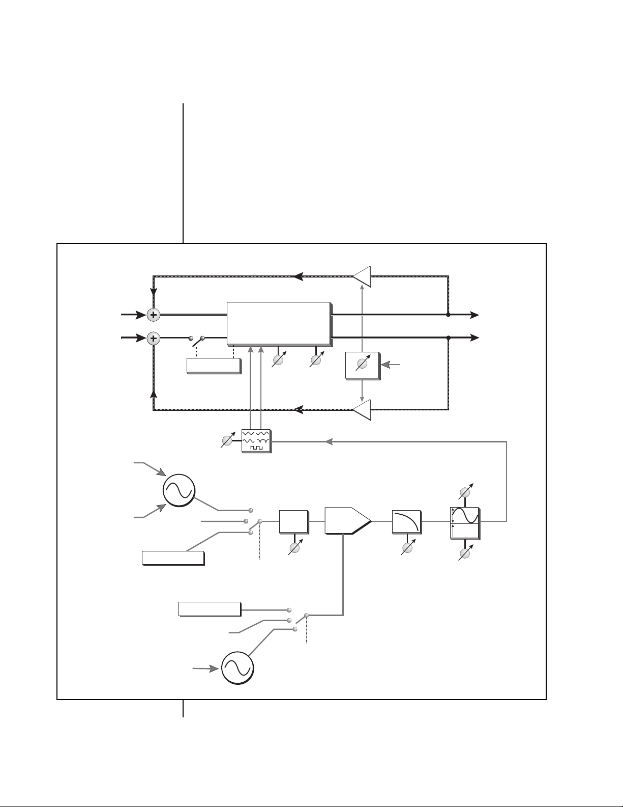
Sweep Rate parameter sets a maximum sweep rate that
will be further modulated by the controller.
• System Tempo - LFO 1 synced to Seq/Arp/MIDI clock
When set to System Tempo, the LFO frequency is
controlled by the EOS system’s internal tempo, and runs
at the tempo division indicated by the Sweep Rate
parameter. In this mode, the LFO1 sweep oscillator will
be restarted at the beginning of its sweep whenever the
EOS arpeggiator or sequencer are resynchronized. In
addition, any non-zero value applied to the LFO Resync
modulation parameter will also restart the sweep when
LFO or System Tempo are selected as sources.
• MIDI - MIDI CC value controls the flange delay.
When the Sweep Source is set to MIDI, LFO sweeping
and synchronization is disabled and the flange delay is
controlled directly by the Flange Delay modulation
parameter. The MIDI controller (contoured by the
Sweep Shape parameter) will modulate the flanger
between the minimum and maximum delay times set
by the Flange Range parameter. This is the only time
that the Flange Delay modulation parameter is active.
The Sweep Rate
parameter is inactive when the
Sweep Source is set to MIDI.
Sweep Rate
This parameter is a rate multiplier or divisor for the
flange sweep. When the Sweep Source is LFO1, this
parameter manually sets the frequency of the internal
sweep LFO1 to a tempo calibrated in beats per minute
(BPM) from .25 to 1000. One complete cycle of the LFO
will occur for each beat. When the Sweep Source is
System Tempo, this parameter sets the multiple or
submultiple of the system’s internal rate to which the
sweep LFO is synchronized, from a submultiple of 1/120
(one cycle per minute at a tempo of 120BPM) to a
multiple of 137 (275Hz at 120BPM).
Sweep Shape
This parameter controls the shape of the modulation
waveform that controls the flanger delay time. The
possible sweep shapes are Triangle (linear sweep),
Curved (a warped Triangle), Sine, Log (an approximately
logarithmic shape which “flattens out” towards shorter
delay times), or Square.
Each Sweep Shape also has a “Dual” selection. When
Dual sweep shapes are selected, a 180 degree (inverted)
copy of the normal LFO waveform is applied to
alternate stages of the flanger. Thus in Mono/Stereo and
Stereo I/O modes, the right output channel flanging is
out of phase with respect to the left channel, which
creates dramatic stereo spatial effects. In Mono I/O
mode, this inverted LFO phase is only applied to

RFX-32 Plug-ins
7
RFX-32
RFX Flanger
internal flanging stages when the Flange Mult
parameter is set greater than x1, and creates a warbling
or phasing effect on the output.
When the Sweep Source is set to MIDI, the Sweep Shape
parameter still controls the shape of the mapping
between the MIDI modulation value and the flanger
delay and whether the flanger is in Dual mode.
Selecting different Sweep Shapes in this mode can help
tune the MIDI controller contour to maximize its
‘playability’.
MIDI Controls
Wet/Dry Mix
FX Input Level
FX Output Level
Flange Delay
LFO1 Sweep Rate
LFO2 S/H Rate
S/H Trigger
LFO Resync
Feedback
Feedback
Feedback increases the depth of the cancellation
notches and generally intensifies the flange effect. This
parameter controls the amount of flanged signal which
is recirculated through each stage of the flanger, from 0
to 100%. It also sets the maximum feedback level which
is further modulated by the Feedback Modulation
parameter.
__
__
Use extra caution with
your sound system and hearing
when operating the RFX Flanger
at high feedback levels.
While the flanger is stable up to 100% feedback, it is still
possible to produce clipping within the flanging stages
and high output levels when the feedback level
approaches 100%. The amount of throughput gain can
also vary greatly depending on which Flange Mult
values and Flange Mode cancellation types are selected,
and where the LFO is in its sweep.
Many interesting tonalities such as bell tones, log
drums, resonant pipes, robot voices, and plucked string
sounds can be produced using high feedback values.
Flange Mult
This parameter controls a “multiplier factor” for the
flanger, changing the number and patterns of cancella-
tions produced by the different flanger stages. The sonic
result of different multiplier values is difficult to
describe, but the general effect is to intensify the
flanging at higher values of the Flange Mult parameter.
Triangle Curved
Square
Sine Log

8
E-MU Systems
RFX-32
RFX Flanger
Note that the various “alternate” cancellation modes set
by the Flange Mode parameter will generally not be
perceptible until the Flange Mult parameter is greater
than 1 and more flanging stages are employed. Varia-
tions of the Flange Mult and Flange Mode parameters
can create a wide variety of different flanging sounds.
The exact effect of the Flange Mult parameter depends
greatly on the I/O mode selected.
• In Mono I/O mode
, the Flange Mult parameter controls
the number of flange stages used in series between the
input and output. To hear the effect of Dual sweep
shapes, the Flange Mult value must be greater than 1
when in Mono mode.
• In Mono/Stereo & Stereo I/O modes
, the Flange Mult
parameter controls the number of stages as well as the
notch patterns produced by the flanger. Again, higher
multiplier values produce more “extreme” effects. Dual
sweep shapes are always applied in these Stereo output
modes, regardless of the Flange Mult value.
Flange Mode
This parameter controls the type of cancellation
produced at the various stages of the flanger. In
conjunction with the Flange Mult parameter, it can
produce widely varying flanging effects. When set to
Positive, all flanging stages use positive cancellation,
producing a “rounded” flanging sound; when set
Negative, using all negative cancellation produces a
more “hollow” effect.
When set to parameter values from “Alt 1” through “Alt
6”, various patterns of alternating polarities are applied
to different stages of the flanger. Note that these
different patterns may or may not be perceptible until
higher values of the Flange Mult parameters are used
and additional flanging stages are employed.
OO
OO
In “Delay Only”mode
the Wet/Dry Mix control can be
used to manually control the
amount of flanging.
Flange cancellation is eliminated entirely when the
Flange Mode is set to Delay Only. In this mode the
input signals are processed straight through the flanger
delay lines without encountering the spectral effects of
cancellation with undelayed signals.
(Note that the pitch
shift produced by the sweeping delays and the shifting
resonances produced by high feedback values will still be
heard.)
When used in Stereo output modes, this Flange
Mode setting is useful for producing subtle spatial
effects at low delay ranges and “double tracking” effects
at higher delay ranges. Because the flange stages are
connected in series, the effects of the Delay Only setting
may be difficult to hear in Mono mode.

RFX-32 Plug-ins
9
RFX-32
RFX Flanger
I/O Mode
The three I/O modes control the input/output
configuration of the flanger:
•
Mono -
In this mode, only the left channel input signal
is processed. All the flange stages are used in series to
produce a single effect signal, which is fed equally to
both left and right outputs.
•
Mono/Stereo
- In this mode, a pseudo-stereo output is
produced by processing only the left input channel.
Multiple flange stages with slightly different character-
istics produce distinct left and right output signals
which create a wide stereo panorama.
•
Stereo -
In this mode, the RFX Flanger operates as a true
stereo flanger: left and right input channels are
processed separately to produce distinct left and right
outputs. The processing applied to each channel is the
same until higher Flange Mult values and alternating
cancellation Flange Modes are encountered, or until
Dual sweeps are used to create inverted flange sweeps
between outputs.
Sweep Smoothing
This parameter applies varying amounts of smoothing
to the sweep control signal after it has been shaped and
before it is applied to control the delay lines.
OO
OO
Sweep Smoothing values
greater than 0 may not be
particularly useful until using the
Log or Square sweep shapes,
which have sharp transitions
that can benefit from some
smoothing.
The main utility of the Sweep Smoothing is for
smoothing the transitions between flange offsets
produced by the flanger’s internal Sample & Hold.
Sweep Smoothing is also applied to the flange offsets set
directly by the Flange Delay modulation parameter. In
this case it can be very useful for smoothing jittery
input from MIDI controllers or limiting the amount of
pitch-shift applied to the signal during radical
modulation changes.
Samp/Hold Source
A sample and hold can be inserted into the modulation
path or turned off. This parameter selects the clock
source for the sample and hold. See “Background:
Sample & Hold” in the RFX operation manual for more
information.
•
Off
- Modulation signal bypasses the Sample & Hold.
•
LFO 2
- an oscillator with a range of .25 to 980 bpm.
•
System Tempo
- LFO 2 synced to Seq/Arp/MIDI clock
• MIDI
- Any time the MIDI CC value
(connected via “Edit
Modulation” in the Setup Edit screen)
changes and is a
number greater than 0, the input to the S & H is sampled
and held on its output. At values below 1, the input is
passed unchanged.

10
E-MU Systems
RFX-32
Envelope Phaser
Envelope Phaser
The Envelope Phaser is very similar to the
RFX Phaser plug in, except that
the modulation section has been replaced with a very flexible envelope
follower. The envelope follower tracks the amplitude of the signal and
converts it to a signal that is applied to the phaser’s phase shift input.
Extensive control over the parameters of the envelope follower allow it to
be carefully tailored to a wide variety of input signals in order to achieve an
equally wide range of sonic results. The Plug-in can perform “self-
modulation” on the audio signal or can respond to the envelope of a
“sidechain” input for cross-modulation effects.
The block diagram of the Envelope Phaser is shown below.
Most parameters are ‘unitless’, which implies that to achieve a particular
effect, the plug-in must be tuned by ear to a particular input signal, rather
than analytically. Experimentation, especially with the Mod Range, Env
Attack, Env Release and Env Shape parameters, is necessary in order to
explore the wide range of sonic effects.
The Envelope Phaser itself is composed of two separate phase shifter
sections. It can be configured either as a true stereo phase shifter with
completely separate signal paths on each channel or a mono phase shifter
using only the left channel for its audio input.
-1
L
Audio Out
R
Audio In L
Audio In R
Modulation Offset
(initial freq)
Modulation
Range
MIDI Mod
11-stage Phaser
11-stage Phaser
I/O mode
mono, stereo,
stereo inverted,
mono L/env R
Attack
Envelope
Gain Release Envelope
Shape MIDI Mod
Offset
MIDI Mod
Range
Feedback
Envelope
Follower
Envelope Phaser Block

RFX-32 Plug-ins 11
RFX-32
Envelope Phaser
A phase shifter creates a series notches in the audio spectrum similar to, but
sounding very different than, an audio flanger. A phase shifter’s notch
spacing remains constant with frequency, unlike a flanger where the notch
spacing is a harmonically related function of delay time. Feedback is used
to increase the depth of the notches and intensify the phase shift effect.
In “inverted stereo mode” the Envelope Phaser is configured in true stereo
but with the envelope follower output inverted on the right channel. This
causes the peaks and notches on the left and right channels to be swept in
opposite directions.
MIDI continuous controllers can be used to control various parameters
such as Modulation Offset, Modulation Range and Feedback.
Envelope Phaser Parameters:
Please refer to the Envelope Phaser block diagram on the previous page to
better understand the effect and modulation routings.
Mod Offset This parameter sets a fixed degree of phase shift that is
added to the Range-scaled envelope before applying it
to the phase shifter. The difference from the RFX Phaser
is that this offset also sets a maximum offset amount
which is further modulated by the Mod Offset MIDI
modulation input.
Mod Range This is similar to the Mod Range control on the RFX
Phaser, controlling the overall extent of phase shift that
is affected by the signal envelope. The difference is that
it now incorporates a negative range, varying from –
100% to 100%. By using a large Mod Offset value and a
negative Mod Range, the relationship between the
signal envelope and the degree of phase is inverted. This
parameter also sets the maximum amount to be
modulated by the Mod Range MIDI modulation input.
Envelope Gain This is a gain control on the envelope input preceding
the envelope follower itself. Use it to adjust the level of
the input signal to achieve optimum excursion of the
envelope follower across the full range of phase shifting
(as scaled by Mod Range.)
Positive gain applied here can be used to compensate
for low level signals, and can also be used to inten-
tionally “peg” the envelope to the maximum phase
shift except on the lowest possible input levels; clipping
of the envelope signal does not affect the quality of the
audio signal path. Negative gain can also be used to
reduce the envelope follower response.
In current EOS releases (as of 4.61) the Emulator front
panel master volume control is applied before the RFX
board, and will affect how the envelope follower reacts

12 E-MU Systems
RFX-32
Envelope Phaser
to input signals. Env Gain can thus be used to make-up
for less-than-full-scale settings of the master volume
control.
Envelope Attack This unit-less parameter sets the attack rate of the
envelope follower, controlling how quickly it responds
to increasing signal levels. It can be varied from the
slowest setting, which is nearly a signal “hold”, to the
fastest setting of 30, which is essentially an instanta-
neous response. Typically useful values are in the range
of 15 to 30.
Envelope Release This parameter varies along the same values as the Env
Attack, setting the rate that the envelope follower
responds to decreasing signal levels. Typically useful
values are in the range of 5 to 25.
Envelope Response
This parameter varies along a continuum of 5 values,
warping the “shape” of the envelope follower response
from fully linear to fully logarithmic. This control is
very useful, especially in conjunction with the Env Gain
and Env Release parameters, for optimizing the way in
which audio signals with different dynamic ranges and
“crest factors” affect the degree of phase shift.
A logarithmic response can often be used to smooth out
the envelope of signals with erratic amplitude response
without slowing the attack time. Conversely, a linear
shape makes the envelope follower more sensitive to
small amplitude changes, and can be used to elicit more
active phase shifter response from signals lacking in
dynamic range.
MIDI Controls
Wet/Dry Mix
FX Input Level
FX Output Level
Modulation Offset
Modulation Range
Feedback
Feedback This parameter controls the amount and polarity of the
signal recirculated through the phase shift network,
from -100% to 100%.
Negative feedback has a somewhat different sonic
character from positive feedback, and when the
Feedback parameter is set negative with any of the
Inverted I/O modes, the left channel will use positive
feedback and the right channel will use negative
feedback.
.The feedback control is more dramatic when the phase
shifter is in a monophonic input mode, since the left
and right phase shift networks are then connected in
series. At values of 100%, the phase shifter will remain
stable, on the verge of self-oscillation.

RFX-32 Plug-ins 13
RFX-32
Envelope Phaser
I/O Mode This parameter sets the input and output and
modulation routing for the phase shifter.
There are 5 different I/O modes:
•Mono L - In this mode, the right input channel of the Envelope Phaser
is ignored. The left and right phase shift networks are connected in
series for a total of 22 stages, and the left input channel supplies both
the audio input and the envelope follower input. The output is mono-
phonic.
•Stereo - In this mode, the Plug-in operates as a true stereo phase shifter,
with separate signal paths for the left and right input channels. The
envelope follower input is derived from the scaled sum of left and right
inputs.
•Stereo Inverted - In this mode, the Plug-in operates in stereo, as for Ste-
reo mode, but the envelope signals driving the phase shifters are
inverted between the left and right sides. This produces a highly spatial
phasing effect in which the “motion” in the left channel is always
matched with an inverted motion in the right channel.
•Mono L/Env R - This mode is the same as Mono L, except that the
envelope signal is derived solely from the right input channel (this is
typically referred to as a “sidechain” input.) This allows right channel
control signals that may be unrelated to the left channel audio input to
drive the phase shifter, allowing cross-modulation between the enve-
lope of one signal and the audio of another.
•Mono Inv L/Env R - This is similar to the Mono L/ Env R side-chain
mode, except that the left input signal is applied to both left and right
sides of the phase shifter. The phase shifter then operates in the same
way as for Stereo Inverted mode, with the left and right output chan-
nels showing inverted modulation.
MIDI Modulation Parameters
The modulation parameters are used to dynamically rescale several of the
user-editable parameters. Those user parameters should be set to the
maximum desired values; these maximum values are then modulated by
the corresponding modulation parameters.
Mod Offset - This modulation input is used to dynamically rescale (from 0
to 100%) the offset specified by the user Mod Offset parameter. The
resulting offset is the bias that is applied to the phase shifter before
envelope modulation takes place. (This parameter was not present in the RFX
Phaser Plug-in.)
Mod Range - This modulation input is used to dynamically rescale (from 0
to 100%) the phase shift range specified by the user Mod Range parameter.
The resulting phase shift range is then further rescaled by the output of the
envelope follower before being applied to the phase shifter.
Feedback - This modulation input is used to dynamically rescale (from 0 to
100%) the amount of feedback specified by the user feedback parameter.

E-MU / ENSONIQ U.S.A.
P.O. Box 660015
Scotts Valley, CA USA
95067-0015
Telephone 831-438-1921
FAX 831-438-8612
EUROPE, AFRICA, MIDDLE EAST
E-MU / ENSONIQ
Suite 6, Adam Ferguson House
Eskmills Industrial park
Musselburgh, East Lothian
Scotland, EH21 7PQ
Telephone +44 (0) 131-653-6556
Table of contents
Other EMU Sound Card manuals