EMX Industries, Inc. KPX 100 User manual

EMX Industries Inc.
4564 Johnston Parkway Cleveland Ohio 44128
Toll Free: 1 800 426-9912
P: 216 518-9888 F: 216 518-9884
Web: http://www.emxinc.com
Programming & Installation Manual
Rev 1.3 4/18/2011


Index Section Reference Page Number
Quick Start Guide Page 1
Introduction & Terminal Connections Page 2 - 3
LED and Tone Indicators Top Page 4
DAP Reset Instructions Bottom Page 4
Single User Code programming A,B,C (i), Page 5
Multi-User Code programming A, B, C (ii) Page 5
Output Mode Configuration D Page 5
Personal Safety E Page 6
Door Forced Open Alarm Programming F Page 6
Output Activation Annunciation G Page 6
User Code Entry Mode (Auto or Manual) H Page 6
Key Acknowledgement Tone Programming I Page 7
Door Propped Open Alarm J Page 7
Mode Selection and Default Values Detail P7 bottom, Pg 8 and Pg 9 Page 7 – 9
Programming and usage examples Pg 9 bottom – Pg 14 top Page 9 – 14
Delete User (Multi-User Mode Pg 14 (D) Page 14
Basic Wiring of Stand alone Door Lock Install Pg 14 (1) Page 14
Basic Wiring of Stand Alone Install W/Inhibit Pg 15 (2) Page 15
Basic Wiring of Interlock System using 2 Keypads Pg 15 (3) Page 15
Examples of Auxiliary terminals Page 16 – 17
Specifications Pg 18 top Page 18
Appendix Pg 18 bottom Page 18
Complimentary User Access Code Log Center of Manual Page 9 - 10

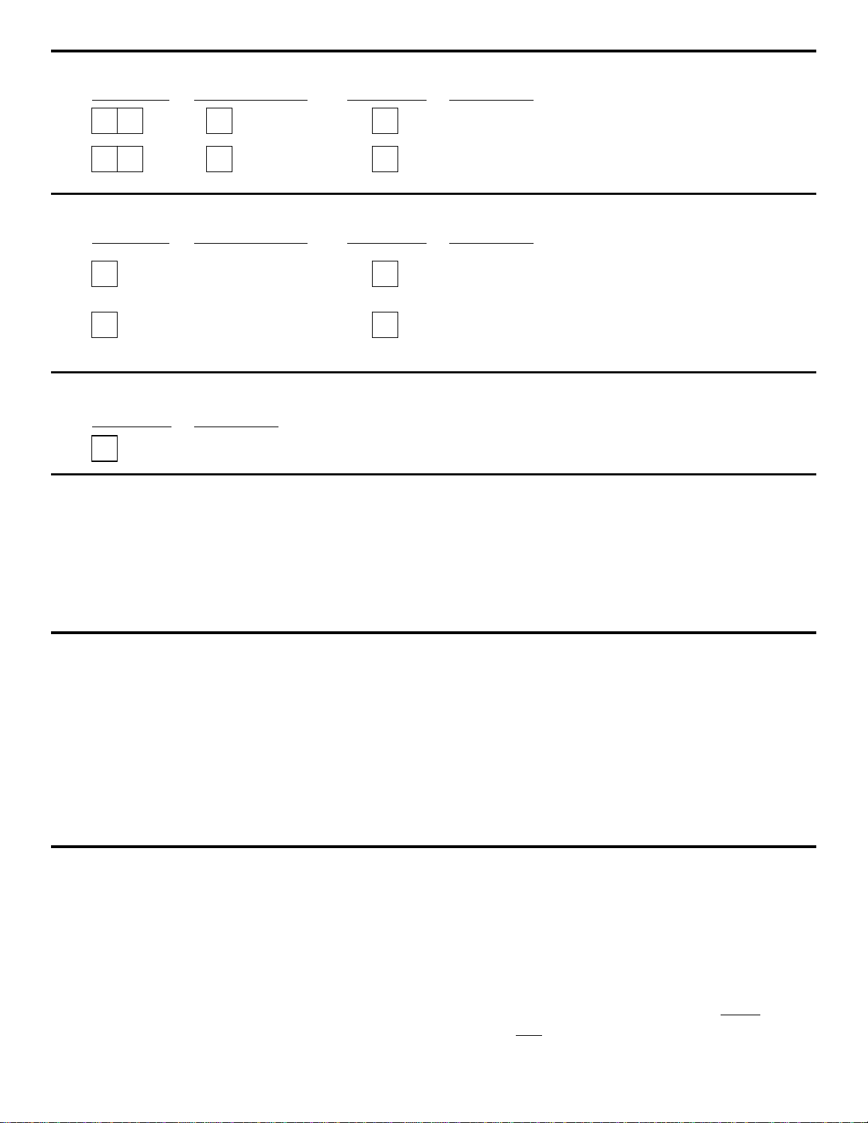
1 0 0 #
Optional additional digits
? ???????
4 0 2 #
*
4 1 #
KPX 100 Quick Start Guide For Multi-User Mode
1. Connect Power 12V DC to 24V AC/DC to terminals (+) and (-)
2. Connect the OUTPUT 1 N/O and COM to OPEN contacts in the operator
(see operator manufacturer’s manual for proper terminals)
3. To Enter Programming mode: Press 0000 *
(This is factory set Master Code change for security)
4. To set the KPX 100 to Multi-user mode: Press 8901 #
(KPX 100 shipped factory set to single user mode)
5. To set PERSONAL MASTER CODE: Press 0 and 4-8 digits and #
To program Relay 1 users
6. To set USER CODE 1: Press 1 then 00 and 4 to 8 digits and #
7. To set USER CODE 2: Press 1 then 01 and 4 to 8 digits and #
8. To set USER CODE 3: Press 1 then 02 and 4 to 8 digits and #
9. Continue as needed up to 100 codes:
10. To set OUTPUT for 2 seconds: Press 402 then #
(40 is output program code. Time may be from 1 – 999 seconds)
11. To Place Relay 1 in Toggle or Latch Mode: Press 41 then #
12. To Exit programming: Press *
For additional detailed information regarding additional functions, connection to door controls, alarms and trouble shooting please refer to the
manual. (see index)
0000 *
8 9 0 1 #
Optional additional digits
? ???????1 01 #
Optional additional digits
? ???????
1 0 2 #
Optional additional digits
0? ? ?????? #
*This must be done after changing modes Record the new code
Pg 1

INTRODUCTION
The KPX 100 is a dual relay output, vandal resistant and weatherproof keypad. The KPX 100
employs durable back-lit all metal key buttons and a rugged metal housing for high traffic and
harsh environment.
The KPX 100 is designed to fit on gooseneck mounts or on posts and walls.
TERMINAL CONNECTIONS FOR THE KPX 100
•12 – 24V AC/DC (POWER INPUT)
Connect to 12-24V AC or DC power supply. The (-) supply and (-) GND are the common
grounding points of the keypad system. No selection jumper is required for the full input voltage
range.
Connect DC power with the (+) and (-) polarity indicated; there is no polarity discrimination for AC
power input.
•Output 1
5 Amp relay dry contacts (type “C”), recommended for door strike controls. Normally Open (N.O.)
and Normally Closed (N.C.) outputs are available. Use the N.O output for Fail-secure locking devices
and the N.C. output for Fail-safe devices. Output 1 relay may be programmed in Start/Stop toggle
mode or timer mode from 1 to 999 seconds.
•Output 2
1 Amp relay dry contact (type “C”), Normally Open (N.O.) and Normally Closed (N.C.). This is an
auxiliary output controlled by the user code 2, which is ideal for controlling security systems and
automatic operators. It is programmable for Start/Stop (toggle) or timing operation from 1 to 999
seconds.
•EG IN
Egress Input is normally open (N.O.) input terminal and connects to ground, with the help of a
normally open button to activate the Output 1 for the same time period as the user code. The egress
button is usually placed inside the facility near the door being controlled by the KPX 100. More then
one egress button may be connected in parallel to the terminal. Leave this terminal open if it is not
used.
Pg 2

•KEY ACT
Keypad Active Output is an NPN open collector output transistor that switches to (-) ground for 10
seconds on each key touch. This may be used to turn on lights, CCTV camera, or buzzers to notify a
guard. This output is rated at I c max: 100mA sink, V c max: 24VDC.
•DU OUT
Duress Output is an NPN open collector output transistor that switches to (-) ground after the Duress
Code is entered. This is used to trigger a zone alarm, or turn on a buzzer to notify a guard. I c max:
100mA sink. V c max: 24VDC.
•Door Sens
Door Position Sensor Input is a normally closed (N.C.) input terminal referring to ground (-). With the
help of a normally closed magnetic door switch, the system will monitor the position of the door and
give the following functions: Note: Always connect this terminal to (-) ground if not used.
Door Auto Re-lock
The system will immediately relock the door after valid access has been gained before
the end of the programmed time for output 1, that prevents unwanted “tailgate” entries.
b. Door Forced Open Alarm
The keypad will generate door forced-open alarm instantly if the door is forced to
open without a valid user entry or egress input. The alarm will last for 60 seconds and
can be stopped with user code 1 or one of the user codes in Group 1 at anytime.
c. Door Propped Open Alarm
When the door is left open longer than the allowable time. The keypad will generate
Door propped open alarm after the expiration of the pre-set door-open-time until the
door is closed again. The door-open-time is programmable from 1 to 999 seconds at location
9.
d. Inter-lock Control
The interlock control output goes to (-) while the door is open in order to give a signal to
disable another keypad that may be in the inter-lock system.
•O/P1INHIB
The Output 1 Inhibit Normally Open (N.O.) input terminal refers to ground (-). Both user code 1 and
Egress button cannot activate output 1 while this terminal is tied to ground (-). It is prepared for
cross wire connection in inter-lock application.
•INT.LOCK
Inter-Lock Control Output Is NPN transistor open collector output. The status is OFF in normal
position and switches to ground (-) immediately for the first 5 seconds after keying in a valid user
code to operate output 1, then it will keep tying to ground during the time the door is position sensor
is open due to the door being open.
Use this output to control the other keypad in an inter-lock system to prevent both doors
opening at the same time. An Inter-lock system is a two door system that always allows only
one door to open during the operation time. While one of the doors in the system is opened,
the other doors keeps closed until the first door is closed to prevent unauthorized people
dashing into a protected area.
•N.C. TAMPER
Normally Closed (N.C.) contact while the keypad is secured on the housing. It is open only
while the Keypad is separated from the housing. Connect this N.C. terminal to the 24 hour
zone of an alarm system if necessary.
Pg 3

LED INDICATORS
•RED
Lights up when output 2 is activated.
•AMBER
This is a status indicator. It’s signal is in synchronization with the pacifier tones from the
built in buzzer.
•GREEN
Lights up when output 1 is activated.
The Pacifier Tones & LED indicator signals
* All pacifier tones can be enabled or disabled through programming options at location 83.
** The output activation beep can be enabled or disabled through programming options at location 81.
The DAP Jumper (Direct Access to Programming)
If the Personal Master Code is forgotten, use the DAP jumper to override the forgotten code
permitting the keypad to enter directly into the programming mode.
You are required to apply the following procedures precisely.
1. Disconnect the power supply.
2. Move the DAP jumper from OFF to ON position.
3. Re-connect power supply (buzzer will be activated).
4. Put the DAP jumper back to OFF position (the buzzer will be deactivated at this time).
5. The keypad is in programming mode and ready to receive new programming data.
6. As the old master code was forgotten it is suggested that you put in a new 4 digit master
code at location 0 first.
7. Enter the new programming data starting from selection “B” in the following summary chart.
The factory-set master code –
Important note
For the owner’s convenience in programming the first time, the factory has put in a master code
of 0000 into the keypad. To insure security in all cases the owner should program in a new
Personal Mater Code to invalidate the factory set master code before use. When using the DAP
reset you must enter the Master Code and save to be able to re-enter program mode in the
future.
STATUS TONES* LED SIGNALS
1. In programming mode --- ON
2. Successful key entry 1 BEEP 1 Flash
3. Successful code entry 2 BEEPS 2 Flashes
4. Unsuccessful code entry 5 BEEPS 5 Flashes
5. DAP jumper not replaced Continuous BEEPS Continuous flashes
6. In standby mode --- 1 Flash in 2 seconds interval
7. Output relay activated 1 second long BEEP** ---
Pg 4

0 0 0 0 * Set system into programming mode with factory set master code.
8 9 0 0
8 9 0 1
#
#
Set system to single user mode, clear all previous data & refreshes system
Set system to multi user mode, clear all previous data & refreshes system
4 0
4 1
4 2
1 to 999 #
#
#
Output 1 in momentary mode from 1 to 999 seconds
Output 1 in Start / Stop Mode (toggle)
Output 1 in Start / Stop Mode (toggle) with
accelerated code
5 0
5 1
5 2
1 to 999 #
#
#
Output 2 in momentary mode from 1 to 999 seconds
Output 2 in Start / Stop Mode (toggle)
Output 2 in Start / Stop Mode (toggle) with
accelerated code
0
2
#
#
#
4 digits, fixed
4 digits, fixed
4 digits, fixed
Personal Master Code & Super User Code
User Code 1 for output 1 with Duress Code function
User code 2 for output 2
1
Personal Master Code & Super User Code
#
100 User codes in Group 1 for output 1 with
Duress Code function
0
1
2
00 to 99
0 to 9
4 to 8 digits
4 to 8 digits
4 to 8 digits 10 User Codes in Group 2 for output 2
#
#
PROGRAMMING OPTIONS – SUMMARY CHART
A) Use the Factory set Master Code to enter into programming mode – on first use
Enter code Validation Comments
B) Set System to single user or multi user mode and refresh the system – Installer
User Mode Options Validation Comments
C) Recording of Personal Master Codes & User Codes – User Programming
i) Recording of the master code and user codes for single user (digits may be repeated)
Locations Entry of Codes Validation Comments
ii) Recording of the master code and user codes for Multi-user (Digits may be repeated)
Locations User Number Entry of Codes Validation Comments
D) Configuration of Output Modes – Installer Programming
Locations Code of Duration Validation Comments
Pg 5

7 0
7 1
7 2
7 6
5 to 10
00
#
#
#
#
After 10 successive false codes, keypad will lock
for 30 seconds
After 10 successive false codes, the Duress output
switches to ground
Selectable from 5 to 10 successive false codes, the
keypad locks for 15 minutes. The keypad can be
reset to release lock with the Master Code at any
time during the locking period.
Removal of all above security settings
8 0
8 0
#
#
1
0
Door Forced Open Alarm is Activated
Door Forced Open Alarm is Disabled
8 1 1 # 1 second notification beep is given to notify the
p
erson outside to open the door when output
relay is activated with a user code or egress
b
utton. Good for the locking device that gives no
sound when it activates, such as magnetic lock.
8 1 0 #
N
otification beep disabled and replaced by 2
short successful code entry beeps for valid
user codes.
8 2 1 # Auto Entry Mode is selected. Key that follows
the user code is not required in code entry. The user
codes must be set in the same digit length as the
Master Code in Auto Entry mode and the code can be
4-8 digits
8 2 0 # Manual Entry Mode is selected. Key that follows
the user code is required in code entry. The user codes
can be 4-8 digits and are not required to be the same
length as the Master Code.
#
#
NOTE: In single user mode, if selection is auto or manual mode, the Master Code and the User Code must be set
to 4 digits length.
E) Personal Safety – Installer Programming
Locations No. of False Entry Validation Comments
F) Door Forced Open Alarm – Installer Programming
Locations Function Code Validation Comments
G) Output Activation Annunciation – Installer Programming
Locations Function Code Validation Comments
H) User Code Entry Mode (Auto or Manual) – Installer Programming
Locations Function Code Validation Comments
Pg 6
8 3
8 3
1
0
#
#
Tones are active on key press
Tones are off. Use for silent environment requirements
9
9
#
#
N
o Propped Open Alarm
Time from 1 to 999 seconds until door
p
ropped open activates alar
m
0
1 to 999
* Keypad exits programming mode and returns to normal operation
I) Pacifier Tones (Key-press Acknowledgement Tones) – Installer Programming
Locations Function Code Validation Comments
J) Door Propped Open Alarm Time – Installer Programming
Locations Function Code Validation Comments
K) Exit Programming Mode
Validation Comments
SINGLE USER MODE OR MULTI-USER MODE SELECTION
They keypad contains two sets of software for owners selection in user code programming. They
are “Single User Mode” and “Multi-User Mode”.
The keypad has been set with a Master Code of “0000” and in single user mode from the factory.
If your required mode is Multi-User, you have to refresh the system with the appropriate
comment code “8901” to set it into Multi-User mode.
Single User Mode (Command Code: 8900)
Single user mode is prepared for the simple users, which allows only one user code to operate
each output. The user codes are fixed to 4 digits and 10,000 code combinations are possible.
User codes can be programmed directly into the User Code Location 1 and Location 2. Please see
programming summary chart section “C”, item i) for details. This mode is always set with the
Auto Code Entry as default. The user is not required to press the # key during code entry. The
user only has to enter the 4 digit user code. The relay will activate for the programmed time.
Note: The system can be set for manual entry with programming option 0 at location 82 if
desired.
Multi-User Mode (Command Code: 8901)
Multi-User mode allows up to 100 individual user codes to operate output 1 and 10 individual user
codes to operate output 2. The user codes can be 4 to 8 digits with over 100 million possible
combinations. The user codes can be set for Auto Entry or Manual Entry with programming
options at Location 82. Manual Entry Mode is the default. The user code followed by the #key is
required.
Once the keypad is programmed in Auto Entry, the Master Code and the User Codes must be set
in the same digit length, and the need for the user code to not be followed by the # key is
required.
Pg 7

MASTER CODE * 8 9 0 0 #
MASTER CODE * 8 9 0 1 #
Default Values
Default Values Comments
401 output 1 in 1 second Momentary Mode
501 output 2 in 1 second Momentary Mode
70 After 10 successive false code the keypad lock for 30 seconds
800 Door forced open alarm is disabled
811 Output relay activation beep is ON
820 User Code Manual Entry Mode ** (for multi-user mode)
821 User code Auto Entry mode ** (for single user mode)
831 audible tone output ON
90 No propped Open alarm
Note: **The default values in Multi-User mode and Single User mode are exactly the same except
the user code entry mode.
Code Entry Limitation in Multi-User Mode due to Duress Code
The system comes with Duress function for the user code 1 in single user mode and all the user
codes in group 1 in Multi-User mode; The Duress Code is set up by the system automatically with
the first digit of the User Code “+2”. To prevent the other user codes from falling into the duress
code, or the duress code from falling into the user codes, the first digit of the “stored” user code
“+2” or “-2” is not allowed for use in User code entry programming. The system will refuse those
code entries.
Example: User code 56789 was stored in the system, then 36789 and 76789 are not allowed for
other user codes.
Set the system to Single User Mode
The system may be set to Single User Mode with the command code “8900” and will retain the
setting until the system is reprogrammed for another mode. Make sure that the Master Code was
already in 4 digits before setting the system to Single User Mode.
--- Single user mode on duty (Please wait 2-3 seconds
until confirmation beeps are heard after the # key is
pressed.
Set the System to Multi-User Mode
The system may be set to Multi-User Mode with the command code “8901” and will retain the
setting until the system is reprogrammed for another mode.
--- Multi-User Mode on duty (Please wait 2-3 seconds
until confirmation beeps are heard after the # key is
pressed.
Refresh the System -- When changing the mode of operation
The system can be changed from Single User Mode to Multi-User Mode; or vice versa with the
above operation command codes.
When this is done, the keypad will reset itself as a fresh unit with default values; and all previous
settings will be cleared. Re-enter the factory master code or new code immediately after system
refresh.
Pg 8
*
MASTER CODE *
LOCATION 1 #
OPTION
LOCATION n #
OPTION n
*
Important Notes:
1) Make sure all User Codes and Master Codes are 4 digits in length if the system is in
Single User Mode. Code entry will not be accepted otherwise.
2) It is necessary to change the Master Code to 4 digits first (no matter if it was 4 or
more than 4 digits in Multi-User Mode) before changing from Multi-User Mode to
Single User Mode.
3) The system takes approximately 2-3 seconds to reset to the new operating mode
after the command code is entered. DO NOT enter any code during this time. Please
wait until the 2 confirmation beeps are heard.
Programming and use of the keypad – Operation Examples
A) Programming Procedures
a) All programming is accomplished through the keypad. The keypad may be programmed in
your shop or at the installation site. Programmed information is stored in non-volatile
memory and will not be lost if the power is removed.
b) When programming is required, it is necessary to set the keypad into programming mode
using the master code and validating with the key.
Note: If the Master Code is forgotten, use the DAP jumper to set the keypad into
programming mode. (See DAP Jumper description in previous section Pg 5 for details)
c) After the keypad is in programming mode, you may go to any location for programming
options one by one. (Please see programming options summary chart for details)
d) You may make continuous programming until all desired options are programmed.
Repeated programming at the same location is allowed if the previous entry was
mistaken.
e) Exit programming mode with the key after all your required options are programmed.
The new information that you have programmed will be saved.
B) Single User Mode Operation – Operation Example
1) Requirement
a) Single User Mode Operation
b) Change factory set Master Code 0000 to a Personal Master Code 3289
c) Set User Code 1 to 8321
d) Set User Code 2 to 6854
e) Set Output 1 to Momentary Mode. 1 second
f) Set Output 2 to Start / Stop (toggle) Mode
g) Set Keypad to lock itself for 15 minutes after 10 successive false codes
Pg 9

000 0 * -----------System has been placed in program mode with factory set Master Code
8 9 0 0 # -----------System has been set for Single User Mode ** (see note (a) below)
0 3 2 8 9
1 8 3 2 1
#
#
---
---
3289 has been stored as the new Personal Master Code & Super User Code
8321 has been stored as User Code 1, with Duress Code function on Output 1
2 6 8 5 4 # ---6854 has been stored as User Code 2, for output 2
4 0 1 # Output 1 has been set to momentary mode with 1 second duration
5 1 # -------------------
Output 2 has been set to Start / Stop (toggle) mode
7 2 1 0 # ---------The keypad has been set to lock for 15 minutes after 10 successive false
codes
* ----------------------------Keypad exits programming mode. All changes are stored, system is
ready to use
*
#
8 3 2 1
6 8 5 4
---------
---------
Output 1 activates for 1 second
Output 2 Starts or Stops (toggle mode)
#
8 3 2 1 --------- Output 1 activates for 1 second
8 3 2 1 --------- Output 2 Starts or Stops (toggle mode)
#
#
1
2
0 3 2 1 --------- Duress output activates (output switches to (-) ground) & Output 1
activates for 1 second
2) Programming – Set the previous requirements into the keypad:
Note: a) ** Enter the single user mode command code “8900” may not be necessary if the
keypad was already in single user mode.
b) In case of wrong entry during programming, cancel with key, or, wait 10 seconds,
then re-try.
3) Operate the Keypad – Taking the data programmed above and other features in default value as reference
a) To command an output, enter it’s user code. Press is not required.
b) The Personal Master Code is a Super User Code to control the outputs. This feature allows
the owner to use only one code to operate several keypads if they have the same
Master Code but different User codes. Enter the personal Master Code and validate via
the key and corresponding output number.
c) The Duress Code does not need to be programmed. The keypad determines it
automatically by increasing the first digit of User Code 1 by two units.
For Example: The User Code 1 is “1234”, then the Duress Code is “3234”, or the
User code 1 is “8321”, then the Duress Code is “0321”.
To activate the Duress Functions, enter the Duress Code
Pg 10

8 3 #
8 3 2 1
---------
---------
Output 1 starts
Output 1 stops
3 2 8 9 ---------Lockout is reset and keypad resumes normal operation
#
Note:
The Duress Code has double actions. It activates the Duress Output and at the same time
activates Output 1 as if User Code 1 has been used. The Duress Code can always activate
or deactivate (in Start / Stop mode) Output 1, but cannot deactivate the Duress Output. Only
the User Codes in Group 1 can reset (deactivate) the Duress Output.
d) The accelerated Code is the first two digits of the User Code. If Output 1 has been
programmed in Start / Stop mode with Accelerated Code at Location 42, it is possible
to activate Output 1 with only the first 2 digits of the User Code. Deactivating Output 1
requires the full User Code 1 to be entered.
Example: Output 1 has been re-programmed to Start / Stop mode with Accelerated Code
(location: 42) with complete code of: 8321 The Accelerate Code will be 83.
e) Enter false codes into the keypad to test the security. The keypad considers 4 digits as
1 code and it generates 5 beeps for each unsuccessful entry. The keypad will lock for 15
minutes after 10 unsuccessful code entries. Normal operation will resume after 15 minutes
have expired or it may be reset with the Master User Code at any time during lockout.
C) Multi-User Operation – Operation Example
1) Requirement
a) Multi-User Mode Operation
b) Change factory set Master Code “0000” to a Personal Master Code “3289”.
c)Set1
st User Code in Group 1 of 8321
d) Set 2nd User Code in Group 1 of 11223
e)Set3
rd User Code in Group 1 of 33331
f)Set1
st User Code in Group 2 of 6854
g) Set 2nd User Code in Group 2 of 54321
h) Set Output 1 to Momentary Mode, 1 second duration
i) Set Output 2 to Start / Stop Mode
j) Set the keypad to lock for 15 minutes after 10 successive false codes
Pg 11

0 0 0 0 ---------System is set to programming mode using factory set Master User Code
*
8 9 0 1 ---------System is set to Multi-User Mode *8 (see note (a) below
#
0 3 2 8 -------- 3289 has been stored as the new Personal Master Code & Super User Code
#9
1 8 3 2 -------- 8321 has been stored as 1st user code in Group 1 with duress
code function
#10 1
1 3 3 2 -------- 33221 has been stored as 3rd user code in Group 1 with
duress code function
#20 3 1
2 6 8 -------- 6854 has been stored as 1st user code in Group 2
#51 4
2 5 4 3 -------- 54321 has been stored as 2n
d
user code in Group 2
#22 1
4 ----------------------------Output 1 is set to Momentary Mode with 1 second duration
#0 1
5 --------------------------------- Output 2 is set to Toggle Mode
#1
7 ------------------------- Keypad is set to lock for 15 minutes after 10 successive false
codes
#2 1 0
* ----------------------------------- Keypad exits programming mode. All changes are stored, system is
ready to use
#
#
8 3 2 1 # ----------------------------------- Output 1 activates for 1 second
1 1 2 1 # ------------------------------- Output 1 activates for 1 second
3
3 3 2 2 # ------------------------------- Output 1 activates for 1 second
1
#
6 8 5 4 # ----------------------------------- Output 2 Starts or Stops (toggle mode)
5 4 3 2 Output 2 Starts or Stops (toggle mode)
1 # --------------------
2) Programming
Note: a) ** Entering the Multi-User Mode Command Code “8901” may not be necessary if the
keypad is already in Multi-User Mode.
b) In case of incorrect entry during programming, cancel with the key, or, wait 10
seconds, then re-try.
3) Operating the Keypad – Taking the data programmed above and other features in default value as
reference
a) To control Output 1 enter any one of the user codes in Group 1 and validate via the
key
b) To control Output 2 enter any one of the user codes in Group 2 and validate via the
key
1 1 1 2 -------- 11223 has been stored as 2n
d
user code in Group 1 with
duress code function
#20 2 3
Pg 12

# -------------------------------
0 3 2 1 # ---Duress output activates (switches to ground) & Output 1 activates for 1 second
3 1 2 2 # ---
Duress output activates 9 switches to ground) & Output 1 activates for 1 second
3
5 3 2 2 # ---
Duress output activates 9 switches to ground) & Output 1 activates for 1 second
1
8 3 #
8 3 2 1
--------------------
-------------
Output 1 starts
Output 1 Starts
Output 1 Stops
1 1 Output 1 Starts
1 1 2 2 --------- Output 1 Stops
3 #
#
c) The Personal Master Code is a Super User Code to control the outputs. This feature
allows the owner to use only one code to operate several keypads if they have the same Master
Code but different User Codes. Enter the Personal Master Code and validate via the key and
the corresponding output number.
d) The Duress codes do not need to be programmed. The keypad determines them
automatically by increasing the first digit in Group 1 by two units. All User Codes
have Duress Code function
Example: User Codes in Group 1 Corresponding Duress Codes
8321 0321
11223 31223
33221 53221
To activate the Duress function, enter the Duress Code(s)
Note:
The Duress Code has double actions. It activates the Duress Output and at the same
time activates Output 1 as if User Code 1 has been used. The Duress Code can always
activate or deactivate (in Start / Stop mode) Output 1, but cannot deactivate the Duress
Output. Only the User Code in Group 1 can reset (deactivate) the Duress Output.
e) The accelerated Code is the first two digits of the User Code. If Output 1 has been
programmed in Start / Stop mode with Accelerated Code) Programming Option
42, for users in Group 1 & Programming Option 52 for user codes in Group2), it is
possible to activate Output 1 with only the first 2 digits of the User Code(s).
Deactivating the Output requires the full User Code(s) in their code group to be
entered.
Example: Output 1 has been re-programmed to Start / Stop mode with Accelerated Code
(Programming Option 42)
With the Complete Code of 1st user in Group 1 of: 8321 The Accelerate Code will be 83.
With the Complete Code of 2nd user in Group 1 of: 11223 The Accelerated Code will be 11.
#
3 2 8 9 # ------------------------------- Output 1 activates for 1 second
1
3 2 8 9 # ------------------------------- Output 2 Starts or Stops (toggle mode)
2
Pg 13

3 2 8 9 ---------Lockout is reset and keypad resumes normal operation
#
*
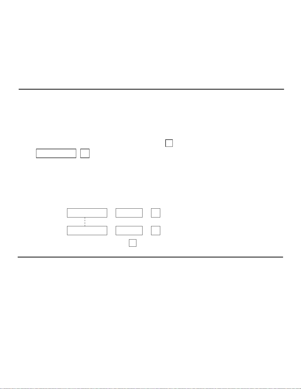
3 2 8 9 ---------Keypad is now in Programming Mode
*
#
1 0 5 #
2 3 #
*
Note:
•Connect the 1N4004 as
close as possible to the lock
in parallel with the lock
terminals to absorb the
back EMF to prevent
damage to the keypad. The
1N4004 is not required if
the electric lock is AC
operated.
•To avoid Electro-Static-
Discharge from interfering
with the operation of the
keypad, always ground the
(-) terminal to earth ground.
•Always connect Door
Sensor terminal to (-)
ground if not used.
f)Enter false codes into the keypad to test the security. The keypad will lock for 15
minutes after 10 unsuccessful code entries. Normal operation will resume after 15
minutes have expired or it may be reset with the Master User Code at any time during
lockout.
D) Delete User (Multi-User Mode)
If you need to delete a user who has left the company or who no longer has authority
To enter the protected area:
1) Enter System Programming mode with the Personal Master Code and the key
2) Enter the User Number (00-99 for Output 1; 0-9 for Output 2) and the key to
delete the user code
If you want to delete User Number 05 in Group 1, press:
If you want to delete User Number 03 in Group 2, press:
3) You may delete other user code(s) in this fashion
4) Exit the programming mode by pressing the key when finished
1) Basic wiring of Stand Alone Door Lock Installation
Pg 14

2) Example of wiring with stand alone door lock with inhibit authorization code
3) Basic wiring of an inter-lock System using two keypads
NOTE:
•Use output 2 as authorization control.
The owner may key in the user code 2
to stop operation of the electric lock
at night or after office hours to
prevent unauthorized access.
•Set output 2 to Start / Stop (toggle)
Mode (Program Option 51) for ON-Off
control.
•Simply connect the “output 1 inhibit”
(O/P 1 INHIB) terminal with output 2
as shown in the wiring diagram. User
code 1 is invalid while the “O/P 1
INHIB” terminal is shunted to ground
with user code 2.
An inter-lock system needs two door
controllers. This application example uses
two KPX 100 with simple cross wire
connection on the “Output 1 Inhibit” and
“Inter-lock Control Output” terminals. It is
necessary to link up the “(-) GND” terminals
of the two keypads as common ground to
achieve the inter-lock logic function.
•Use keypad to open door from outside
•Press egress button to open door from
inside
•Connect the door magnetic sensors on
the doors to monitor position
•While door 1 is open, door 2 is forced to
stay closed or vide versa
•Use N.O. relay output for fail-secure lock;
and N.C. output for fail-safe lock
•Please consult “NOTE” stated in
application example (1)
Pg 15

(B) DOOR SENS
a) Door Auto Relock – the system will
immediately re-lock the door after a valid
access has been gained to prevent “tailgate”
entry.
b) Door Forced-open alarm – The keypad will
generate an instant alarm if the door is
forced to open. Enable the function with
Program Option 801
c) Door Propped Open Alarm – The keypad
will generate an alarm if the door is left
open longer than the pre-set time. Enable
the function with Program Option 9 with
duration of 1 to 999 seconds.
With the help of a normally closed door d) Inter-lock Control – When the door is open
Position sensor (usually a magnetic door the inter-lock output of the keypad will give
switch)on the door to set up the following a (-) command to de-activate the other
functions. keypad in an inter-lock system.
Application examples for auxiliary terminals
Pg 16

Pg 17
Other manuals for KPX 100
1
Table of contents
Other EMX Industries, Inc. Keypad manuals


