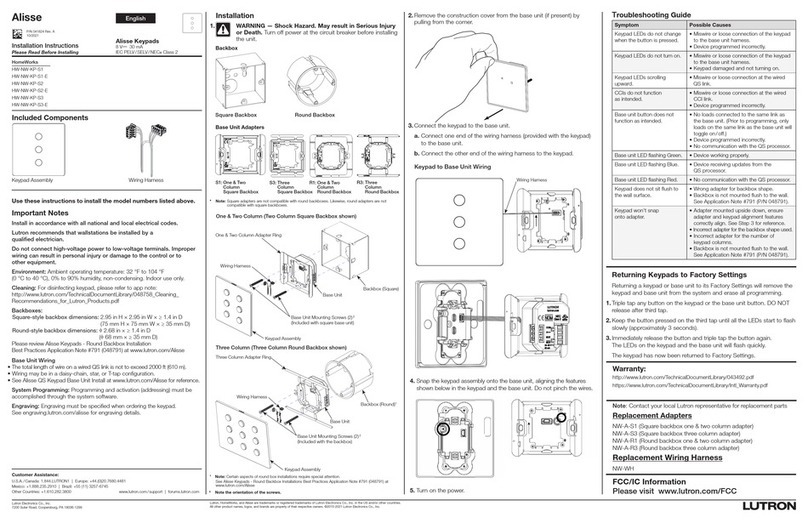
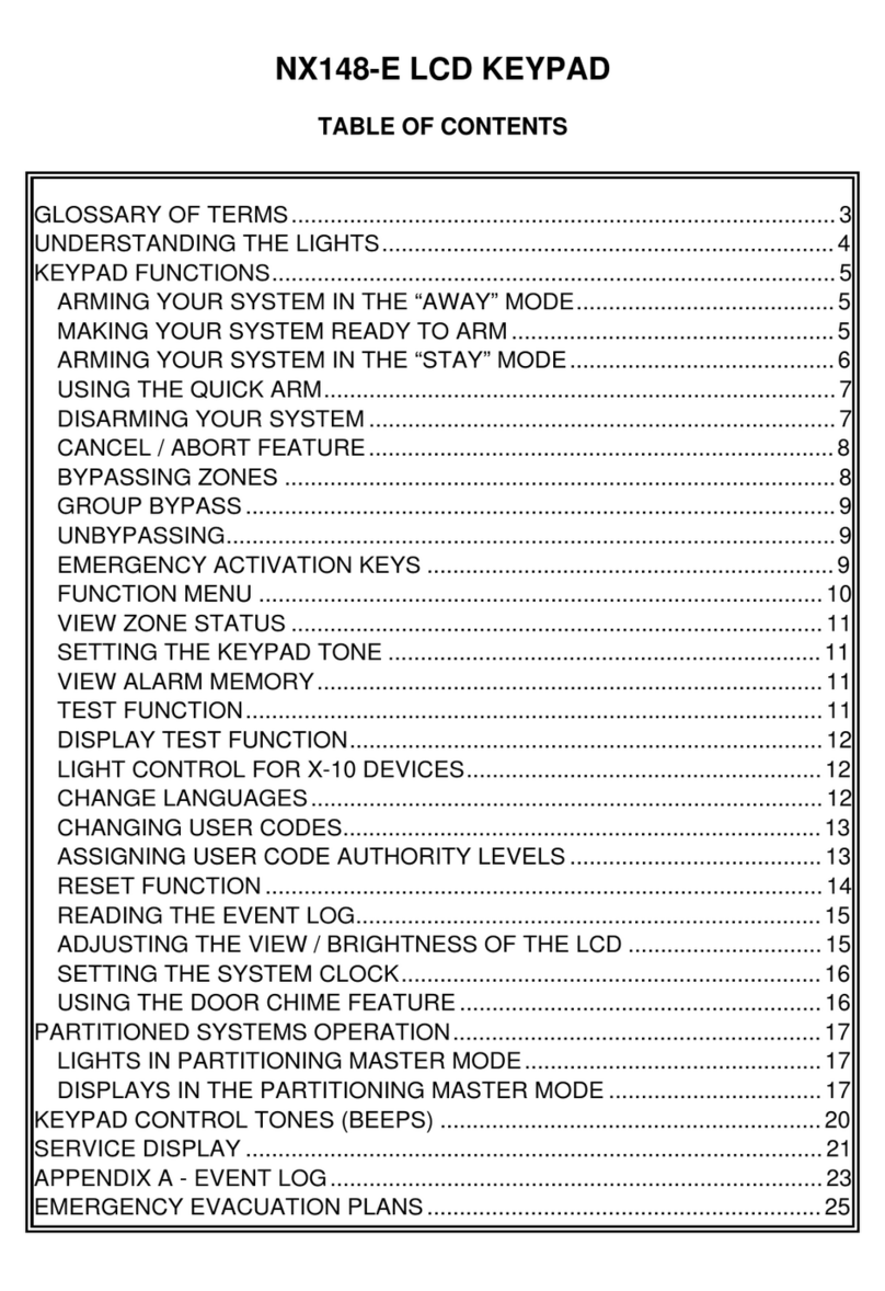
PRESCO PRDA 3 Series User manual

123
“PRESCO” KEYPAD SYSTEM.
INTRODUCTION.
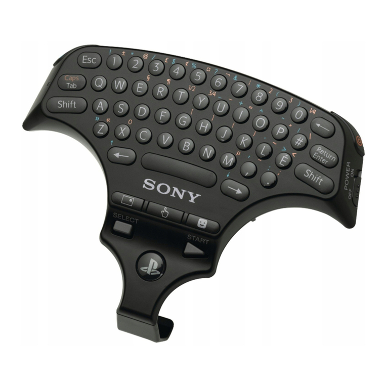
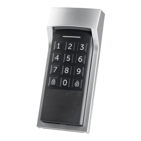
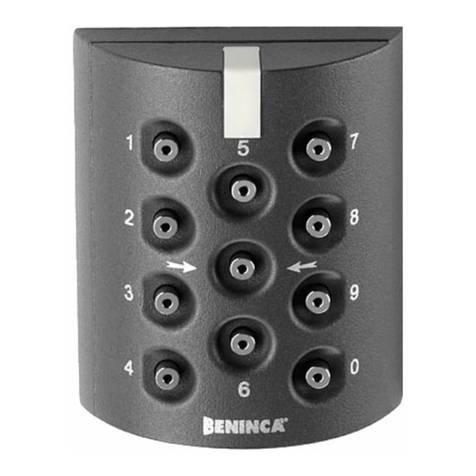
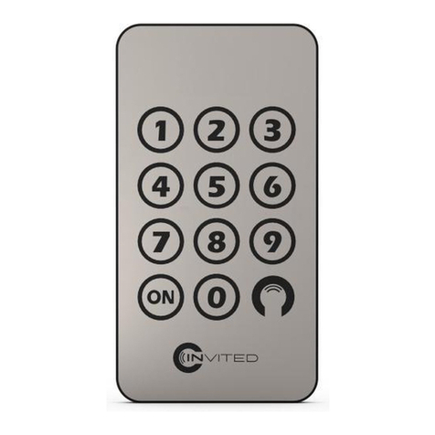
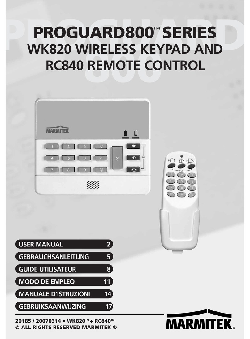
The PRDA Digital Keypad System
utilises the latest microprocessor
technology to operate most electric
door locking devices on the market.
These keypads offer the ability to
access restricted areas by using easy
to remember codes. A Lexan overlay
protects the tactile (not membrane or
rubber) buttons in heavy traffic areas
and also offers water and dust
resistance to the keypad. Additional
keypads (total of 10) can be connected
to allow remote activation from a
reception desk etc.
FEATURES
Split system for maximum security, (Keypad & Decoder).
Door forced open detection.
Door Open Too Long (DOTL) function.
EGRESS function.
29 client programmable user codes (125 optional).
Digits can repeat ie. 12321.
3 to 7 digit management and user codes.
Minimum 19 million possible user code combinations.
Up to 10 keypads can be connected to one decoder.
10 year non volatile memory.
Audible/visual confirmation.
Sealed “Tactile” buttons.
17mm. thin surface mounting.
Hidden screw mounting.
Water resistant (with use of optional gasket).
Operating Temperature Range: 0
C to 70
C.
SPECIFICATIONS
DECODER Voltage: 12-24 Volt A.C./D.C.
Current: 20 mA. + 45 mA relay when
operated (24 Volt D.C).
35 mA. + 65 mA relay when
operated (24 Volt A.C).
KEYPAD Standby current: 0.25 mA.
ELC contacts: 30 Volt, 5 Amp A.C./D.C.
(Electric Latch Control) SPDT.
DOTL output: 1 Amp max. sink current
(Door Open Too Long) (open collector).
Maximum Keypad 1 KM (0.6 Miles) (max.
Decoder separation: return resistance 100
. Non
shielded).
Package size: 79 mm/123 mm/45 mm.
Weight: 200 gms.
MOUNTING
Use the supplied template to mark the position for mounting
and wire cut-out hole.
Disconnect all power during wiring.
Do not over-tighten terminal screws on decoder.
DECODER TERMINAL DESCRIPTIONS
Negative output or Ground from Power Supply.
AC or DC 12-24 Volt from Power Supply.
Data (white wire from Keypad).
(Electric Latch Control) 5 Amp. Relay operates
momentarily with each correct code entered. This
output can be varied for operating times between 1
and 255 seconds (factory set for 10 seconds).
A. Use CM and NO for fail/secure operation.
ie. power applied to unlock latch.
B. Use CM and NC for fail/safe operation.
ie. power removed to unlock latch.
A normally closed input to GND, goes open circuit
when the door is open. The DOOR input is used to
detect when the door has been opened for use by
the door forced open, DOTL and automatic re-lock
functions. The automatic re-lock function turns the
ELC output off 1 second after the door opens,
allowing the door to automatically re-lock when
closed. Note: If the DOOR input is to be used it
must be enabled via Memory 6.
(Door Open Too Long) open collector output
operates when the door has been left open for
longer than the programmed DOTL time or when
the door has been forced open. See
DOOR OPEN
TOO LONG
and
DOOR FORCED OPEN
DETECTION
sections. The DOTL output is
capable of sinking up to 1 Amp.
A normally open or normally closed input to GND.
See
SELECT EGRESS SWITCH TYPE
section.
When this input is activated the ELC output will
turn on and remain on until the input is removed.
Once the EGRESS input has been removed, the
ELC output will continue to operate for the
programmed momentary time and the automatic
re-lock and DOTL functions are also enabled.
OPERATING MODE RULES
1/ 1 beep = successful code (ELC output turned on).
2/ 2 beeps = successful code (ELC output turned off).
3/ 5 beeps = management code entered.
4/ a long beep = a non existent code.
a pause then a long beep = 5 unsuccessful “tries”.
(System is locked out for 1 minute, if enabled in mem 5).
The
and Memory number are NOT required in the
OPERATE mode.
5/ Cancel a wrong entry with
, then re-try.
THE MEMORIES
Memory0 Memory1 Memory2 Memory 3 Memory 4
Toggle
operation user
codes.
Momentary
operation user
codes.
Selects
EGRESS
switch type.
Enable/disable
door forced
open detection.
Door Open
Too Long
time.
Memory5 Memory6 Memory7 Memory 8 Memory 9
Enable/disable
1 minute
lockout.
Enable/disable
Door input for
reed switch.
Use two
codes to
operate ELC.
ELC relay
operate
time.
Management
code.
BASIC SETUP SEQUENCE
1/ Select EGRESS switch type (Currently N/O). [Memory 2]
2/ Set ELC OPERATE TIME (Currently 10 seconds).
[Memory 8]
3/ Enable/Disable DOOR INPUT (Currently disabled).
[Memory 6]
4/ Set Door Open Too Long time (Currently 60 seconds).
[Memory 4]
5/ Enable/Disable DOOR FORCED OPEN DETECTION
(Currently enabled). [Memory 3]
6/ Enable/Disable 1 MINUTE LOCKOUT (Currently
disabled). [Memory 5]
7/ Enable/Disable USE TWO MOMENTARY CODES
(Currently disabled). [Memory 7]
8/ Program MANAGEMENT CODE. [Memory 9]
9/ Program USER CODES. [Memory 1 & Memory 0]
NOTE: Use the Program Link for steps 1 to 8 above (and
step 9 if the management code is not used).
Remove link when finished.
“Series 3”
ELC
GND
AC-DC
DTA
IMPORTANT!
DOOR
DOTL
EGRESS
Enter

456
SELECT EGRESS SWITCH TYPE. (MEMORY 2)
Factory preset to: Normally Open - N/O.
Memory 2 stores whether the EGRESS switch to be used is
Normally Open (N/O) or Normally Closed (N/C).
Note that this memory should only be altered if a N/C
EGRESS switch is to be used, otherwise the EGRESS switch
should be left as N/O.
1/ The program link must be on.
2/ The single digit after the 2determines which type of
EGRESS switch is to be used. The digit after the 2must
be either 0or 1.
Select Switch type..
.................N/C EGRESS switch selected (Warble).
.................N/O EGRESS switch selected (Warble).
ELECTRIC LATCH CONTROL (ELC) OPERATE TIME.
(MEMORY 8)
Factory preset to: 10 seconds.
Memory 8 stores the time the ELC relay operates for when a
momentary user code is used. It can be set to operate
momentarily from 1 to 255 seconds.
1/ The Program link must be on.
2/ The digits after the 8determine the operate time for ELC.
The value must be between 1and 255.
Set ELC Time..........
.................Sets ELC for 5 sec operation (Warble).
.............Sets ELC for 60 sec operation (Warble).
DOOR INPUT ENABLE. (MEMORY 6)
Factory preset to: Door Input Disabled.
Memory 6 stores whether the decoder is to use the door reed
switch input. When the door reed switch input is enabled the
automatic re-lock, Door Open Too Long and Door Forced
Open functions are then enabled.
Note that if the Door input is enabled, but a N/C reed switch
is not used, the PRDA will not function correctly.
1/ The program link must be on.
2/ The single digit after the 6determines whether the door
reed switch input is enabled. The digit after the 6must be
either 0or 1.
Enable/Disable Door reed switch input
.................Enables door input (Warble).
.................Disables door input (Warble).
DOOR OPEN TOO LONG (DOTL) TIME. (MEMORY 4)
Factory preset to: 60 seconds.
Memory 4 stores the time that the door is allowed to remain
open before the DOTL output is activated. It can be set from
0 and 9999 seconds. The DOTL time commences after the
door has been unlocked and opened through the use of a
valid code or EGRESS. If the door is held open for longer
than the programmed DOTL time then the DOTL output will
activate until the door is closed.
Note that a 0value for the DOTL time will give the door an
infinite time to remain open for, ie. DOTL is disabled.
1/ The program link must be on.
2/ The digits after the 4determine the DOTL time to use.
The value must be between 0and 9999.
Set DOTL time.........
.................Set DOTL time to infinite (Warble).
.............Set DOTL time to 30 secs (Warble).
..........Set DOTL time to 480 secs [8 mins]
(Warble).
DOOR FORCED OPEN DETECTION. (MEMORY 3)
Factory preset to: Door Forced open Detection Enabled.
Memory 3 stores whether the decoder is to detect when the
door has been opened without the use of a valid code or
EGRESS. If detection is enabled and the door is forced
open, the DOTL output will activate for 30 seconds or until the
door is closed again (whichever is the longer time). However
if detection is disabled, then the PRDA will go into the DOTL
time-out loop as soon as the door is opened. If the door then
remains open for longer than the programmed DOTL time,
the DOTL output will activate until the door is closed again.
Note that Door Forced Open Detection must be disabled if
the door can be opened without the use of a code or
EGRESS switch.
1/ The program link must be on.
2/ The single digit after the 3determines whether door
forced open detection is enabled. The digit after the 3
must be either 0or 1.
Enable/Disable Door Forced Open Detection
.................Disables door forced open detection
(Warble).
.................Enables door forced open detection
(Warble).
DISABLE 1 MINUTE LOCKOUT. (MEMORY 5)
Factory preset to: 1 Minute Lockout Disabled.
Memory 5 stores whether the PRDA is to lockout all codes for
1 minute after 5 invalid codes have been tried. Enabling of
the lockout feature may be desirable for higher security.
Disabling of the lockout feature is necessary if door access
must be guaranteed at all times.
1/ The program link must be on.
2/ The single digit after the 5determines whether the lockout
is enabled or disabled. The digit after the 5must be either
0or 1.
Enable/Disable 1 Minute Lockout
................ 1 minute lockout Enabled (Warble).
................ 1 minute lockout Disabled (Warble).
USE TWO MOMENTARY CODES. (MEMORY 7)
Factory preset to: Do NOT use Two momentary Codes.
Memory 7 can be used to set up the PRDA as a “two code”
system. What this means is that two different momentary
user codes stored in the PRDA must be used before the ELC
relay will operate for the time programmed in memory 8. The
value stored in memory 7 is the time (in seconds) allowed
between the two codes being entered. If the value stored
here is zero (0) then only one code is required to operate
ELC. If a second different code has not been entered before
the programmed time has elapsed then the PRDA will wait for
another two codes to be used.
Note that when “Two codes” is enabled (Memory 7 is not set
to 0) then the toggle user codes (Memory 0) are not valid.
1/ The program link must be on to set Memory 7.
2/ The digits after the 7determine the “Two codes” time to
use. The value must be between 0and 255.
Set “Two codes” time
................ Only one momentary code required
(Warble).
............. Allow 30 secs between the 2 codes
(Warble).
............. Allow 60 secs between the 2 codes
(Warble).

789
PROGRAMMING
PROGRAMMING MODE RULES.
1/ The
key = Add.
2/ The
key = Delete.
3/ Enter memory number (
for momentary operation codes,
for the management code, etc.) before any
programmable information. This ensures the information is
directed to the correct memory location.
4/ Warble = successful Add or Delete.
5/ Long beep warns that either codes are already in use, too
long or short, or more than 29 codes have been used.
6/ Press each digit within 10 seconds after the preceding
digit, otherwise information will be lost. If a wrong number
is pressed, wait 10 seconds then start again.
NOTES:
1/ After trying the example codes below, delete them then
add your own unique code/s. Avoid obvious codes like
1234.
2/ Up to 29 different user codes can be stored between
Memory 1 & 0.
3/ Repeating digits, including the
, are allowed in codes
eg.
provided that
is not the first digit.
4/ Codes can be from 3to 7digits in length.
5/ There are NO factory preset codes programmed.
THE MANAGEMENT CODE. (MEMORY 9)
Memory 9 stores the Management code which allows the
Program mode to be entered from any keypad without the
Program link. Use this feature if regularly changing codes, or
the decoder is difficult to access. As supplied, no
Management code exists.
To add, change or delete the Management code, the
Program link must be on. The digits after the
are the
Management code.
Add Management Code
..........246 is the management code (warble).
..........369 has now over written 246 (warble).
................................. Restore operate mode.
Using the Management code
..................Program mode entered (5 beeps).
..........456 added to memory 1 user codes
(warble).
.................................Operate mode entered automatically.
Note: that the system automatically returns to the Operate
mode after a single management function has been
performed. ie. add or delete a code. If the
management function was not successful, the system
still returns to the Operate mode (after a long beep).
Note: how 369E replaces the Program link function but with
the addition of the 5 beeps to clearly indicate which
mode is current. All momentary and toggle user code
programming examples on pages 6 & 7 below could
be done with the management code. 369 is an
example only. With link ON either overwrite it with a
new code or delete with
. REMOVE LINK.
Note: If after entering the Management mode you decide
not to add or delete a code, then press
to return to
the Operate mode.
Note: If the Management code is forgotten, use the program
link to over write the forgotten code with a new code.
This feature obsoletes factory preset or “house codes”
which can compromise security.
MOMENTARY OPERATION USER CODES. (MEMORY 1)
The codes programmed into Memory 1 are used to operate
the ELC relay for the length of time set in Memory 8 (ELC
OPERATE TIME).
Note: The digits after the
are the momentary operation
user code.
Add user codes ...... Link on both pins (Program mode).
..........567 is added to memory 1 (warble).
..........678 is also added to memory 1 (warble).
Try user codes........ Park link on 1 pin (Operate mode).
..................ELC operates (1 beep).
..................ELC operates with this code also
(1 beep).
Delete a user code .
..........678 is deleted from memory 1 (warble),
567 remains.
Delete all user codes
.....................Deletes all codes stored in Memory 1
(warble).
................................. Restore operate mode.
TOGGLE OPERATION USER CODES. (MEMORY 0)
The codes programmed into Memory 0 are used to toggle the
state of the ELC relay. These codes can be used as override
codes to keep a door open during certain times. These codes
are useful for a business where the door is to be unlocked
during business hours but kept locked after hours, requiring
people to use a momentary code to open the door.
Note: that when the ELC relay has been turned on (door
unlocked) by using a toggle operation code, then the
momentary operation codes are not valid until the ELC relay
is turned off (door locked) and also that the DOTL time out
routine does not start until the ELC relay is turned off.
Note: The digits after the
are the toggle operation user
code.
Add toggle codes ..
......... 852 is added to memory 0 (warble).
......... 741 is also added to memory 0 (warble).
Try toggle codes....
................. ELC relay turns on (1 beep).
................. ELC relay turns off (2 beeps).
Delete a toggle code
......... 852 is deleted from memory 0 (warble),
741 remains.
Delete all toggle codes
.................... Deletes all codes stored in Memory 0
(warble).
................................ Restore operate mode.
Design Philosophy - Problems and Solutions.
1/ Most keypads contain the switching relay and control
wiring within the keypad housing. A skilled person could
easily bypass the keypad function simply by removing it
then manipulating the control wiring, a disastrous
situation. “Presco” is “split” in 2 parts, so that the decoder
can do all the processing at a remote protected
environment. The code is transmitted between keypad
and decoder in “computer” language, therefore cutting or
shorting wires won’t compromise security.
2/ Typical keypad installations require 7 or more wires thus
increasing labour and cost. “Presco” uses only 3 wires to
operate the door release, LED/buzzer feedback of code
entry, acknowledgment of correct code, state of door
strike, remote management code programming and
power. Up to 10 keypads can be connected to PDA by
simple parallel wiring. No synchronising is required.

10 11 12
PRDA A.C. Wiring Diagram
PRDA D.C. Wiring Diagram
NOTE: The 3 1N4004 diodes referred to in the A.C.
and D.C. diagrams are packaged with the PRDA.
OTHER MODELS AND ACCESSORIES.
PRDA/125 PRDA with 125 user codes.
P2 1 Amp. 30 Volt Control and Duress SPDT relays,
timed or toggled operation, 29 user codes, 12
Volt D.C. operation.
P6 Six (6) open collector logic outputs, timed or
toggle operation, 29 user codes, 12 Volt D.C.
operation.
PRE Additional keypad encoder for any “Presco”
decoder. Up to 10 per system allowed.
PKG Watertight gasket for PRE.
PRC Magnetic card reader. 12-24 Volt A.C./D.C.
Compatible with any “Presco” decoder.
PROTECTION.
The NIDAC “Presco” keypad system has a high immunity to
all types of static, EMF, and RF transmissions including those
of Police and CB radio systems. Reverse polarity and
overvoltage protection from lightning strike up to 10Kv is
provided.
WARRANTY.
NIDAC SECURITY PTY. LTD. will repair or replace this
product if proven to be faulty (excluding accidental or
malicious damage) under the 36 month warranty offered from
the date of purchase.
As NIDAC SECURITY PTY. LTD. or it’s agents do not perform
the final installation, inspection or training in the use of this
product, they cannot be held liable for injury, loss or damage
directly or consequentially arising from the use or misuse of
this product.
“Presco” is a pending Trade Mark belonging to NIDAC
SECURITY PTY. LTD. The “Presco” Keypad system is
protected by provisional and pending patents in various
countries including Australia.
The software design is protected internationally and remains
the intellectual property of NIDAC SECURITY PTY. LTD.
Design improvement and specification are subject to change
without notice. All designs are copyright 1992.
Designed and Manufactured by:
NIDAC SECURITY PTY. LTD.
2 Cromwell Street, 3125 Burwood Victoria Australia.
Phone: (03) 9808-6244 Fax: (03) 9808-9335
International: 61+3+9808...
“
”
PRDA Series 3 Instructions.doc 3/10/97Revision 6
