ITALIANO FRANÇAIS ENGLISH
KP500DV/N
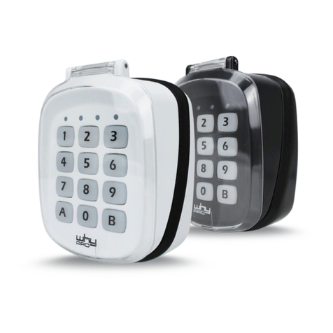
Tastiera display vocale
Clavier avec afficheur
et interface vocale
Vocal display keypad
1
3 8
4
5 67
ELKRON
TEL. +39.011.3986711 – FAX +39.011.3986703
www.elkron.com – mail to: info@elkron.it
ELKRON
è un marchio commerciale di
URMET
S.p.A
.
ELKRON
est une marque commercial d
’URMET
S.p.A.
ELKRON
is a trademark of
URMET
S.p.A
.
Via Bologna, 188/C - 10154 Torino (TO) – Italy
www.urmet.com
ATTENZIONE: IN QUESTO DOCUMENTO SONO RIPORTATE SOLO ALCUNE
INDICAZIONI ESSENZIALI SUL PRODOTTO. PER ULTERIORI E DETTAGLIATE
INFORMAZIONI FARE RIFERIMENTO AI MANUALI DELLE CENTRALI MP500.
DESCRIZIONE GENERALE
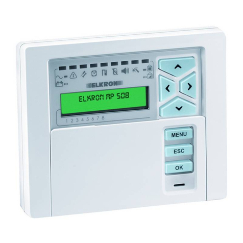
La tastiera KP500DV/N per interni, consente di comandare e programmare i sistemi
della serie MP500. Essa dispone di un interfaccia vocale che consente l’ascolto
ambientale e l’ascolto/registrazione dei messaggi.
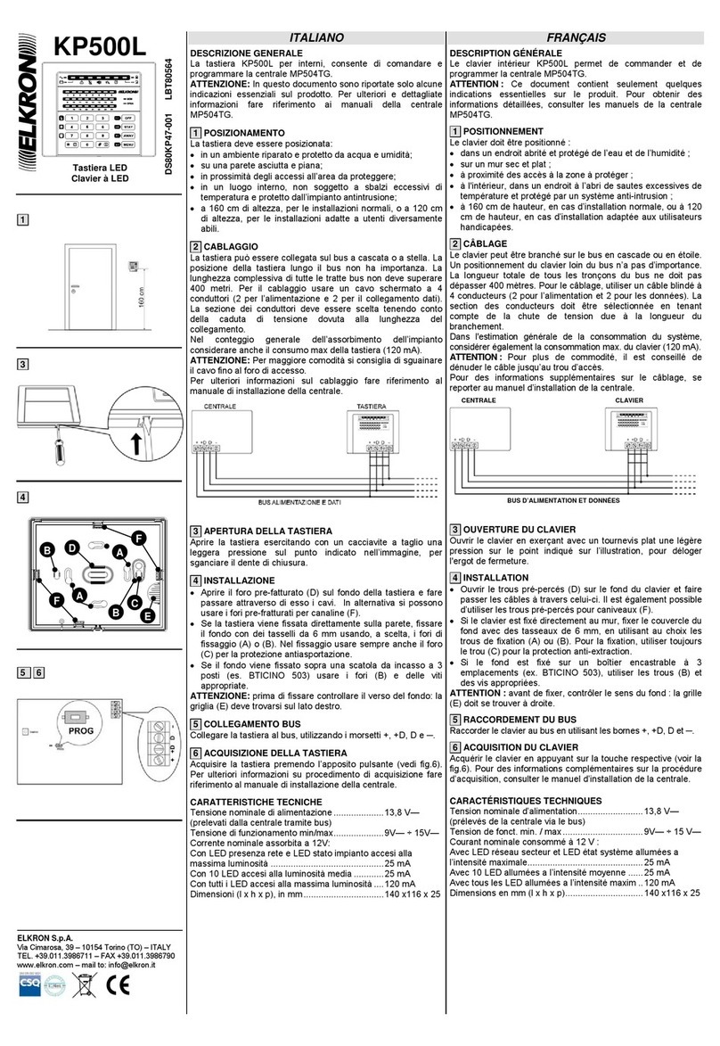
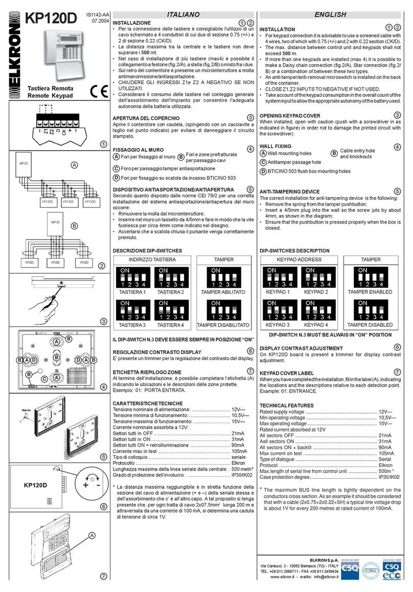
1 POSIZIONAMENTO
La tastiera deve essere posizionata:
•in un ambiente riparato e protetto da acqua e umidità;
•su una parete asciutta e piana;
•in prossimità degli accessi all’area da proteggere;
•in un luogo interno, non soggetto a sbalzi eccessivi di temperatura e protetto
dall’impianto antintrusione;
•a 160 cm di altezza, per le installazioni normali, o a 120 cm di altezza, per le installazioni
adatte a utenti diversamente abili.
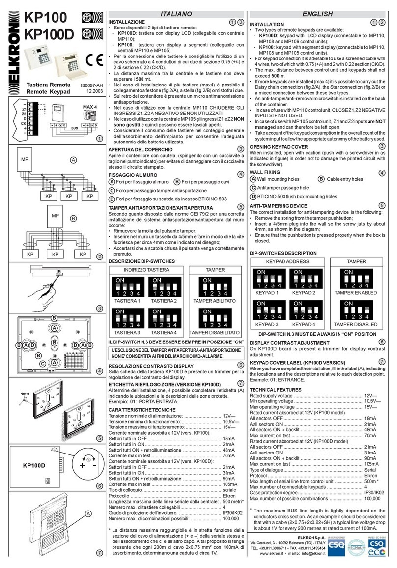
2 CABLAGGIO
La tastiera può essere collegata sul bus a cascata o a stella. La posizione della tastiera
lungo il bus non ha importanza. La lunghezza complessiva di tutte le tratte bus non deve
superare 400 metri. Per il cablaggio usare un cavo schermato a 4 conduttori (2 per
l’alimentazione e 2 per il collegamento dati). La sezione dei conduttori deve essere
scelta tenendo conto della caduta di tensione dovuta alla lunghezza del collegamento.
Nel conteggio generale dell’assorbimento dell’impianto considerare anche il consumo
max della tastiera (120 mA).
Per il collegamento del bus fonia utilizzare un doppino ritorto. Se più tastiere vengono
connesse al bus fonia occorre utilizzare un collegamento a cascata. La lunghezza
complessiva del bus fonia non deve superare 300 metri.
ATTENZIONE: Per maggiore comodità si consiglia di sguainare il cavo fino al foro di
accesso. Per ulteriori informazioni sul cablaggio fare riferimento al manuale di
installazione della centrale.
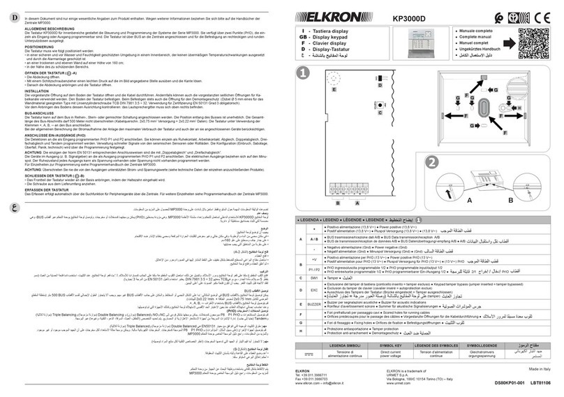
3 APERTURA DELLA TASTIERA
•Aprire il coperchietto.
•Con un cacciavite a taglio esercitare una leggera pressione sul punto indicato
nell’immagine e sganciare il dente di chiusura.
•Quindi chiudere il coperchietto ed aprire la tastiera.
4 INSTALLAZIONE
•Aprire il foro prefatturato (D) sul fondo della tastiera e fare passare attraverso di
essi i cavi. In alternativa si possono usare i fori prefratturati per canaline (F).
•Se la tastiera viene fissata direttamente sulla parete, fissare il fondo con dei tasselli
da 6 mm usando, a scelta, i fori di fissaggio (A) o (B). Nel fissaggio usare sempre
anche il foro (C) per la protezione antiasportazione.
Se il fondo viene fissato sopra una scatola da incasso tonda o rettangolare a 3 posti (es.
BTICINO 503) usare i fori (Ao B) e delle viti appropriate.
5COLLEGAMENTO BUS
6 COLLEGAMENTO BUS FONIA
Collegare il doppino ritorto della linea fonia ai morsetti A1 e A2. Nel collegare il bus fonia
non è necessario tener conto della polarità.
7 ACQUISIZIONE DELLA TASTIERA
Acquisire la tastiera premendo l’apposito pulsante PROG. Per ulteriori informazioni su
procedimento di acquisizione fare riferimento al manuale di installazione della
centrale.
8 CHIUSURA DELLA TASTIERA
Richiudere la tastiera tramite la vite fornita a corredo (G).
CARATTERISTICHE TECNICHE
Tensione nominale di alimentazione...............13,8 Vcc
(prelevati dalla centrale tramite bus)
Tensione di funzionamento min/max...............9 Vcc÷15 Vcc
Corrente nominale assorbita a 12 Vcc:
A riposo,solo LED presenza rete.....................20 mA
In funzione,con retroilluminazione a liv.1.........32 mA
In funzione,con retroilluminazione a liv.4.........120 mA
In funzione ascolto messaggi..........................200 mA max
Dimensioni (L x H x P), in mm.........................151x125x29
ATTENTION : CE DOCUMENT CONTIENT SEULEMENT QUELQUES INDICATIONS
ESSENTIELLES SUR LE PRODUIT. POUR OBTENIR DES INFORMATIONS DETAILLEES,
CONSULTER LES MANUELS DES CENTRALES MP500.
DESCRIPTION GÉNÉRALE
Le clavier intérieur KP500DV/N permet de commander et de programmer les systèmes de
la série MP500. Ce clavier dispose d’une interface vocale assurant tant l’écoute ambiante
que l’écoute et l’enregistrement des messages.
1 POSITIONNEMENT
Le clavier doit être positionné :
•dans un endroit abrité et protégé de l’eau et de l’humidité ;
•sur un mur sec et plat ;
•à proximité des accès à la zone à protéger ;
•à l'intérieur, dans un endroit à l’abri de sautes excessives de température et protégé par
un système anti-intrusion ;
•à 160 cm de hauteur, en cas d’installation normale, ou à 120 cm de hauteur, en cas d’installation
adaptée aux utilisateurs handicapés.
2 CÂBLAGE
Le clavier peut être branché sur le bus en cascade ou en étoile. Un positionnement du clavier
loin du bus n’a pas d’importance. La longueur totale de tous les tronçons du bus ne doit pas
dépasser 400 mètres. Pour le câblage, utiliser un câble blindé à 4 conducteurs (2 pour
l’alimentation et 2 pour les données). La section des conducteurs doit être sélectionnée en
tenant compte de la chute de tension due à la longueur du branchement.
Dans l'estimation générale de la consommation du système, considérer également la
consommation max. du clavier (120 mA).
Pour brancher le bus téléphonique, utiliser une paire torsadée. Si plusieurs claviers sont
connectés au bus téléphonique, il faut utiliser un branchement en cascade. La longueur totale
du bus téléphonique ne doit pas dépasser 300 mètres.
ATTENTION : Pour plus de commodité, il est conseillé de dénuder le câble jusqu’au trou d’accès.
Pour des informations supplémentaires sur le câblage, se reporter au manuel d’installation de la
centrale.
3 OUVERTURE DU CLAVIER
•Ouvrir le couvercle.
•Déloger l'ergot de fermeture en exerçant avec un tournevis plat une légère pression sur
le point indiqué sur l’illustration.
•Puis, fermer le couvercle et ouvrir le clavier
4 INSTALLATION
•Ouvrir
le trou pré-percés (D) sur le fond du clavier et faire passer les câbles à travers
celui-ci. Il est également possible d’utiliser les trous pré-percés pour caniveaux (F).
•Si le clavier est fixé directement au mur, fixer le couvercle du fond avec des tasseaux de
6 mm, en utilisant au choix les trous de fixation (A) ou (B). Pour la fixation, utiliser
toujours le trou (C)pour la protection anti-extraction.
•Si le fond est fixé sur un boîtier encastrable ronde ou rectangulaire à 3 emplacements
(ex. BTICINO 503), utiliser les trous (Aou B) et des vis appropriées.
ATTENTION : avant de fixer, contrôler le sens du fond : la grille du haut-parleur (E) doit se
trouver en haut à droite.
Pour la certification EN50131 Grade 3, toujours utiliser le tasseau en position C, même si le
clavier est fixé au boîtier encastrable. Il n’est pas obligatoire pour le Grade 2 ou inférieur.
5 RACCORDEMENT DU BUS
Raccorder le clavier au bus en utilisant les bornes +, +D, D et ─.
6 RACCORDEMENT DU BUS TÉLÉPHONIQUE
Brancher la paire torsadée de la ligne téléphonique aux bornes A1 et A2. Au cours du
branchement du bus téléphonique, ne tenir pas compte de la polarité.
7 ACQUISITION DU CLAVIER
Acquérir le clavier en appuyant sur la touche respective PROG. Pour des informations
complémentaires sur la procédure d’acquisition, consulter le manuel d’installation de la centrale.
8 FERMETURE DU CLAVIER
Refermer le clavier à l’aide de la vis livrée de série (G).
CARACTÉRISTIQUES TECHNIQUES
Tension nominale d’alimentation.......................... 13,8 Vcc
(prélevés de la centrale via le bus)
Tension de fonct. min. / max................................ 9 Vcc÷15 Vcc
Courant nominale consomméà 12 Vcc :
Au repos, avec DEL de prés. sect. uniquement ... 20 mA
En fonct., avec rétroéclairage au niv. 1................ 32 mA
En fonct., avec rétroéclairage au niv. 4................ 120 mA
En fonction d’écoute des messages .................... 200 mA max.
Dimensions en mm (L x H x P) ............................ 151x125x29
CAUTION: IN THIS DOCUMENT THERE ARE ONLY PRESENT SOME
ESSENTIAL INDICATIONS ABOUT PRODUCT. FOR FURTHER AND MORE
DETAILED INFORMATION, REFER TO MANUALS CONCERNING MP500
CONTROL PANELS.
GENERAL DESCRIPTION
Keypad KP500DV/N for interiors enables to control and program series MP500
systems. Providing a vocal interface enabling environmental listening and message
listening/recording.
1 POSITIONING
Keypad must be positioned:
•in an environment that is sheltered and protected from water and humidity;
•on a dry and level wall;
•in the vicinity of the accesses to area to be protected;
•in an inner location which is not subjected to excessive sudden rises/falls in
temperature, and is protected by anti-burglar system;
•at 160 cm height for normal installations, or at 120 cm height for installations suitable to
disabled users.
2 WIRING
Keypad can be connected on bus either in a cascade or star. Keypad position along
bus is not important. The overall length of all bus sections must not exceed 400 metres.
For wiring, use 4 lead screened cable (2 leads for power supply and 2 leads for data
connection). Lead section must be chosen taking into account voltage drop caused by
connection length.
In counting out overall system absorption, also consider max consumption in keypad
(120 mA).
For telephony bus connection, use twisted duplex cable. If more Keypads are connected
to telephony bus, a cascade connection has to be used. Telephony bus overall length
must not exceed 300 metres.
CAUTION: For better comfort, you are suggested to unsheathe the cable up to access hole.
For further information about wiring, make reference to control panel installation manual.
3 KEYPAD OPENING
•Open the lid.
•With the sharp edge of a screwdriver, exert a slight pressure on point indicated in
picture and release closing tooth.
•Then, close the lid and open the keypad.
4 INSTALLATION
•Open the pre-manufactured hole (D) on the bottom of keypad and run cables
through them. As an alternative, pre-manufactured holes for cable trays (F) can be
used.
•If Keypad is directly fastened on the wall, fasten bottom cover with 6 mm blocks using
either (A) or (B) fastening hole at will. In fastening, always use anti-theft protection hole
(C) too.
•If bottom is fastened over round or rectangular a 3-place built-in box (e.g. BTICINO
503), use holes (Aor B) and suitable screws.
CAUTION: before, fastening, check bottom back: speaker grid (E) must be at top right
position.
For EN50131 Degree 3 classification, always use the anchor bolt in position C, even if
the keypad is fixed to a flush-mounting box. This requirement is not mandatory for
Degree 2 or lower installations.
5 BUS CONNECTION
Connect Keypad to bus using pins +, +D, D and ─.
6 TELEPHONY BUS CONNECTION
Connect telephony line twisted duplex cable to pins A1 and A2. In connecting telephony
bus, polarity needs not be taken into account.
7 KEYPAD CAPTURE
Capture Keypad by pressing special pushbutton PROG. For further information about
capture procedure, refer to manual concerning control panel installation.
8 KEYPAD CLOSING
Close the keypad during the screw provided (G).
TECHNICAL CHARACTERISTICS
Nominal supply voltage........................................13.8 Vdc
(taken in from control panel via bus)
Min/max operation voltage ...................................9 Vdc ÷ 15 Vdc
Current absorbed at 12 Vdc:
At rest, only mains presence LED........................20 mA
When working, with back-lighting at level 1..........32 mA
When working, with back-lighting at level 4..........120 mA
Depending on message listening .........................200 mA max
Dimensions (w x h x d)
in mm ...................................
151x125x29
DS80KP72-001B LBT80881
G
CLAVIER
CENTRALE
BUS TÉLÉPHONIQUE
BUS D’ALIMENTATION ET DONNÉES
Carte de
synthèse
vocale
SV500N
