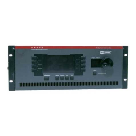
Dolby Laboratories DA20 User manual

MODEL DA20
DIGITAL FILM
SOUND PROCESSOR
Installation Manual
ISSUE 6 Part No. 91341

INSTALLATION MANUAL
FOR
MODEL DA20 DIGITAL
FILM SOUND PROCESSOR
Dolby Laboratories Incorporated
U.S.A. 100 Potrero Avenue, San Francisco, CA 94103
Tel: 415-558-0200; Fax: 415-863-1373
U.K. Wootton Bassett, Wiltshire SN4 8QJ
Tel: +44 (0) 1793 842100; Fax: +44 (0) 1793 842101
www.dolby.com
WARRANTY INFORMATION–USA: Warranty on the product covered by this manual is subject to the limitations and disclaimers set forth
in the warranty disclaimer originally shipped with the product and also printed on the back of the invoice.
Digital decoding covered by the following U.S. patents: 4,790,016, 4,914,701, 4,799,260 4,941,177, 5,109,417, 5,142,656, 5,230,038, 5,274,740,
5,297,236, 5,357,594, 5,463,424, 5,583,962, 5,608,805, and other worldwide patents granted and pending.
All requests for repairs or information should include the unit serial number to assure rapid service.
Dolby and the double-D symbol are registered trademarks of Dolby Laboratories.
©1997 Dolby Laboratories Inc. ISSUE 6 Cat. No. 611A
S97/11285/11537
Dolby Part No. 91341

i
TABLE OF CONTENTS
INTRODUCTION
Specifications ............................................................................................................................................... iii
About This Manual ..................................................................................................................................... iv
SECTION 1 EQUIPMENT REQUIRED/POWER REQUIREMENTS
1.1 Equipment Required .................................................................................................................. 1-1
1.2 Power Requirements .................................................................................................................. 1-1
1.3 Regulatory Notices ..................................................................................................................... 1-2
SECTION 2 INITIAL SETUP AND INSTALLATION
2.1 Mounting the Digital Soundhead ............................................................................................. 2-1
2.2 Electrical Connections to the Digital Soundhead................................................................... 2-4
2.3 Making a Custom Video Cable ................................................................................................. 2-5
2.4 Connection to Motor Start Relays–For 2 Projector Installations .......................................... 2-9
2.5 Connection to Dolby Cinema Processors .............................................................................. 2-10
2.5.1 Installation of DA20 with CP55 ................................................................................ 2-10
2.5.2 Installation of DA20 with CP65 ................................................................................ 2-40
2.5.3 Installation of DA20 with CP200 .............................................................................. 2-43
2.5.4 Installation of DA20 with CP45 ................................................................................ 2-82
2.5.5 Installation of DA20 with CP500 .............................................................................. 2-85
SECTION 3 CAT. NO. 700 DIGITAL SOUNDHEAD ALIGNMENT
3.1 Cat. No.700 Digital Soundhead Alignment ........................................................................... 3-1
3.2 Test Setup with Oscilloscope .................................................................................................... 3-1
3.3 Focus Adjustment ....................................................................................................................... 3-2
3.4 Exciter Lamp Level Confirmation and Adjustment .............................................................. 3-3
3.5 Film Path Alignment .................................................................................................................. 3-3
3.6 Optical Alignment ...................................................................................................................... 3-4
SECTION 4 MODEL DA20 ALIGNMENT
4.1 Cinema Processor Type Selection............................................................................................. 4-1
4.2 Digital Soundhead Delay Adjustment..................................................................................... 4-2
4.3 Digital Surround Delay Adjustment ........................................................................................ 4-3
SECTION 5 THEORY OF OPERATION
5.1 DA20 Basic Functions................................................................................................................. 5-1
5.2 Discussion of Changeover Technique ..................................................................................... 5-3
5.3 Format Control ............................................................................................................................ 5-3
5.4 Auxiliary Data Channel ............................................................................................................. 5-4
5.5 Dolby Digital Decoder Block Diagram .................................................................................... 5-5
SECTION 6 OPERATING INSTRUCTIONS
6.1 How to Identify Sound Tracks on Prints ................................................................................. 6-1
6.2 Film Threading ............................................................................................................................ 6-1
6.3 Displays ........................................................................................................................................ 6-2
6.4 Format Control and Auto Digital Modes ................................................................................ 6-4
6.5 Auxiliary Data Channel ............................................................................................................. 6-7
6.6 Two Projector Changeover Operation ..................................................................................... 6-7
6.7 Operation With An Automation System ................................................................................. 6-8

ii
SECTION 7 MAINTENANCE AND ADJUSTMENTS
7.1 Digital Soundhead Maintenance .............................................................................................. 7-1
7.2 Print Cleanliness ......................................................................................................................... 7-2
7.3 Adjustments................................................................................................................................. 7-2
SECTION 8 UNIT SERVICING / IN CASE OF DIFFICULTY
8.1 Troubleshooting During the Show........................................................................................... 8-1
8.2 Problem Identification................................................................................................................ 8-2
8.3 Determining Software Revision No. ........................................................................................ 8-5
8.4 Starting and Program Loading ................................................................................................. 8-6

SPECIFICATIONS
iii
DA20 Digital Film Sound
Adaptor
Inputs
Digital Soundhead
Inputs for up to two Dolby Cat.
No.699/700 Digital Soundheads
or comparable inboard readers.
Audio
For use with Dolby CP200
Cinema Processors (separate
input not required for CP65 and
CP55).
Motor Start
Two control inputs detect motor
start signals from projectors 1 and
2.
Projector Changeover
Single input. Ground to select
projector 2, open for projector 1.
Outputs
Audio
Left, Center, Right, Left
Surround, Right Surround, Mono
Surround and Subwoofer (L, C, R,
LS, RS, S and SW).
Auxiliary Data Port
RS-232 standard 8 bit data
available.
Cinema Processor Interface
Format Control inputs and
outputs connect via specific
cables to the Dolby CP65, CP200
or CP55, sensing the currently
selected format and providing
automatic switching as required.
Front Panel Indicators
Signal Present
One LED per channel indicates
that a signal level above –40 dB is
present at the analog output of
the DA20.
SR•D Digital
Indicates that valid digital data is
being processed.
SR•D Analog
Indicates that the system has
selected Dolby Stereo SR (analog)
operation.
Motor 1/ Motor 2
Indicates “motor running” signals
used for changeover.
Maximum Output
20 dB above Dolby level.
Dynamic Range
92 dB.
Projector Speed Tolerance
23 – 26 frames/second, nominal.
Construction
All plug-in modules are
constructed using printed circuit
cards, 96-way DIN connectors.
Conforms to FCC class A EMI
specification.
Dimensions
3 units high, rack mounting; 129
x 283 mm (5.25 in. x 19 in.).
Maximum projection behind
mounting surface 362 mm
(14.25in.).
Shipping Weight
9 kg (20 lb.).
Power Requirements
85 to 265 VAC, 50 - 60 Hz.
Power Consumption
Maximum 100 Watts; typical 60
Watts.
Ambient Operating
Temperature
Up to 40˚C.
Cat. No. 700 Digital
Soundhead
Size
152.4 mm h. x 101.6 mm d. x
254mm w. (6 in. x 4 in. x 10 in.).
Shipping Weight
10.5 kg (24 lb.).
Power Requirements
Exciter lamp requires
approximately 3.5 A at 10 V,
provided by integral exciter lamp
power supply. 85 to 264 VAC;
50- 60 Hz.
Power Consumption
Maximum 100 Watts; typical 60
Watts.
Projector Changeover
Indicates the status of the
changeover control lines.
Power Supply
+15 V, –15 V and +5 V.
Data Status
Numeric LED display indicates
data recovery efficiency from
digital print.
Signal Level
Four-LED display indicates
digital audio signal level for each
channel.
DA20 Internal Controls
System Delay
Three rotary switches set time
delay to achieve synchronization
of sound with picture through
different mounting positions for
digital soundhead. Adjustable
from 4 to 132 frames (16 to 528
perforations) in 1/4-frame
increments.
Surround Delay
Single rotary switch sets delay for
left and right surround channels.
0-140 ms adjustable in 10 ms
increments.
Cinema Processor Type
Selects format protocol and
signal switching for Dolby CP65,
CP200, or CP55.
DA20 System
Specifications
Output Level
300 mV for Dolby Level (20 dB
below maximum modulation) to
match Dolby Cinema Processors.
Frequency Response
L, C, R, LS, RS, S: 20 Hz to 20 kHz
±0.5 dB. SW: 20 Hz to 120 Hz
±0.5 dB.
Noise Level
More than 72 dB CCIR/ARM
below Dolby level at DA20
outputs.
INTRODUCTION
This manual contains essential information on the installation and alignment of the Dolby
Model DA20 Digital Film Sound Processor. It is designed to operate with one of Dolby
Laboratories’ model CP500, CP200, CP65, CP55, or CP45 Cinema Processors to allow
decoding and correct playback of the Dolby Digital optical soundtrack format.
The components of the system are:
Model DA20 SR•D Digital Film Sound Processor
The rack-mounted electronic chassis containing the necessary electronics to drive one or
two Cat. 700 Digital Soundheads, and decode the scanned digital soundtrack into 5.1
channels of high quality audio.
The Cat. No. 700 Digital Soundhead
The soundhead is a film-driven mechanical film transport assembly that provides a stable
film path with a light source, optics, and a CCD (Charge Coupled Device) array. These
components are used to scan digital data from a Dolby Digital print.
The Cat. No. 700 is shipped with a standard 10 meter video cable and a self-contained
Exciter Lamp Power Supply. One Cat. No. 700 is standard with each system; a second
Cat. No. 700 may be purchased for systems requiring changeover.
DA20-to-Cinema Processor Interface Kit
These interface cables connect format control and audio signals from the DA20 to the
Cinema Processor. Some Cinema Processor types require upgrading to take full
advantage of all digital channels produced by the DA20.
About this manual
This manual is intended to be used by individuals who are qualified in the area of cinema
sound installation and service. The basic day-to-day operation of the DA20 is covered in
the DA20 Users’ Manual.
This installation and alignment manual covers the procedures necessary to ensure that
the theatre sound system is accurately aligned to standards that have been established by
Dolby Laboratories. Following these procedures will ensure that the theatre sound
system will accurately reproduce the soundtrack as director and sound mixers intended.
The DA20 Digital Film Sound Processor and Cat. No. 700 Digital Soundhead work
together with Dolby Cinema Processors CP500, CP200, CP65, CP55 or CP45 to provide
the best possible signal to the cinema sound system. The projector, the Dolby processor,
the power amplifiers and the loudspeakers, as well as the auditorium itself, must be
considered when aligning the system for optimum performance. Refer to the appropriate
Cinema Processor manual for alignment instructions for the A and B chains.
iv

The system alignment procedure is divided into two parts:
1. The mechanical alignment of the Cat. No. 700 Digital Soundhead.
2. The electronic adjustment of the DA20 electronics chassis.
CAUTION
This Installation Manual is for use by qualified personnel only. To avoid electric shock do not perform
any servicing other than that contained in the User’s Manual unless you are qualified to do so.
v

1-1
SECTION 1
EQUIPMENT REQUIRED/POWER REQUIREMENTS
1.1 Equipment Required
1.2 Power Requirements
1.3 Regulatory Notices
1.1 Equipment Required
The following equipment is required for installation:
a. Triggered sweep oscilloscope and probes with 20 MHz or greater bandwidth.
b. Voltmeter for measuring Exciter Lamp Power Supply (11 Vdc)
c. Cat. No. 69T Dolby Tone Test film
d. Cat. No. 1010 Sync Test film (supplied)
e. Cat. No. 1011 Channel ID Test film (supplied)
f. Cat. No. 1012 Dolby Level Test film
g. 2mm Allen Wrench for Focus Adjustment (supplied)
h. 3mm Allen Wrench for Digital Soundhead Flywheel Installation (supplied)
i. 9/16" (15mm) Open end Wrench
j. No. 2 Phillips Screwdriver
k. Tools for removing existing Top Reel Arm from Projector
1.2 Power Requirements
DA20
The Dolby Model DA20 may be operated from any nominal 120Vac or 240Vac power
source. Voltage selection is automatic within the DA20. The switching power supply
used in the DA20 may be used with mains voltages in the range 85-265 Vac, 50-60 Hz
without adjustment for input voltage.
FUSE—T 2 Amp 5mm x 20mm Time Lag
The fuse may be inspected or replaced by removing the power cord from the unit and opening the
hinged cover of the power entry module. The fuse holder can then be removed.
Cat. No. 700 Digital Soundhead Exciter Lamp Power Supply
The Cat. No. 700 Digital Soundhead contains an internal exciter lamp power supply and
is intended for operation at nominal 120Vac or 240 Vac input and nominal 10Vdc output.
The switching power supply used in the Cat. No. 700 may be used with mains voltages in
the range 85-265 Vac, 50-60 Hz without adjustment for input voltage.
FUSE—T 2 Amp 5mm x 20mm Time Lag
The fuse may be inspected or replaced by removing the power cord from the unit and opening the
hinged cover of the power entry module. The fuse holder can then be removed.

1-2
1.3 Regulatory Notices
FCC
This equipment has been tested and found to comply with the limits for a Class A digital
device, pursuant to part 15 of the FCC Rules. These limits are designed to provide
reasonable protection against harmful interference when the equipment is operated in a
commercial environment. This equipment generates, uses, and can radiate radio
frequency energy and, if not installed and used in accordance with this instruction
manual, may cause harmful interference to radio communications. Operation of this
equipment in a residential area is likely to cause harmful interference in which case the
user will be required to correct the interference at his or her own expense.
UL
Troubleshooting must be performed by trained technicians. Do not attempt to service the
unit unless you are qualified to do so.
WARNING: Check that the units have been set to the correct supply voltage and that the
correct fuses have been installed. To reduce the risk of fire, replace the fuses only with
the same type and rating. Do not use a ground-lifting adaptor and never cut the ground
pin on the three-prong power plug.
UK
Connections for United Kingdom.
WARNING: THIS APPARATUS MUST BE EARTHED.
As the colours of the cores in the mains lead may not correspond with the coloured
markings identifying the terminals in your plug, proceed as follows:
• The core which is coloured green and yellow must be connected to the terminal in the plug which is
marked with the letter Eor by the earth symbol , or coloured green or green and yellow.
• The core which is coloured blue must be connected to the terminal which is marked with the letter
Nor coloured black.
• The core which is coloured brown must be connected to the terminal which is marked with the
letter Lor coloured red.
Europe
This unit complies with the requirements of EN 60065, EN 55103-1 and EN 55103-2 when
installed in an E2 environment in accordance with this manual.

1-3
GB
D
F
I
D
S
NL
IMPORTANT SAFETY NOTICE
This unit complies with the safety standard IEC65. To ensure safe operation and to guard
against potential shock hazard or risk of fire, the following must be observed:
• If the unit has a voltage selector, ensure that it is set to the correct mains voltage for your supply. If there
is no voltage selector, ensure that your supply is in the correct range for the input requirement of the unit.
• Ensure fuses fitted are the correct rating and type as marked on the unit.
• The unit must be earthed by connecting to a correctly wired and earthed power outlet.
• The power cord supplied with this unit must be wired as follows:
Live—Brown Neutral—Blue Earth—Green/Yellow
IMPORTANT – NOTE DE SECURITE
Ce materiel est conforme à la norme IEC65. Pour vous assurer d'un fonctionnement sans danger et de prévenir
tout choc électrique ou tout risque d'incendie, veillez à observer les recommandations suivantes.
• Le selecteur de tension doit être placé sur la valeur correspondante à votre alimentation réseau.
• Les fusibles doivent correspondre à la valeur indiquée sur le materiel.
• Le materiel doit être correctement relié à la terre.
• Le cordon secteur livré avec le materiel doit être cablé de la manière suivante:
Phase—Brun Neutre—Bleu Terre—Vert/Jaune
WICHTIGER SICHERHEITSHINWEIS
Dieses Gerät entspricht der Sicherheitsnorm IEC65. Für das sichere Funktionieren des Gerätes und zur Unfallverhütung
(elektrischer Schlag, Feuer) sind die folgenden Regeln unbedingt einzuhalten:
• Der Spannungswähler muß auf Ihre Netzspannung eingestellt sein.
• Die Sicherungen müssen in Type und Stromwert mit den Angaben auf dem Gerät übereinstimmen.
• Die Erdung des Gerätes muß über eine geerdete Steckdose gewährleistet sein.
• Das mitgelieferte Netzkabel muß wie folgt verdrahtet werden:
Phase—braun Nulleiter—blau Erde—grün/gelb
NORME DI SICUREZZA – IMPORTANTE
Questa apparecchiatura è stata costruita in accordo alle norme di sicurezza IEC 65. Per una perfetta sicurezza ed
al fine di evitare eventuali rischi di scossa êlettrica o d'incendio vanno osservate le seguenti misure di sicurezza:
• Assicurarsi che il selettore di cambio tensione sia posizionato sul valore corretto.
• Assicurarsi che la portata ed il tipo di fusibili siano quelli prescritti dalla casa costruttrice.
• L'apparecchiatura deve avere un collegamento di messa a terra ben eseguito; anche la connessione rete deve
avere un collegamento a terra.
• Il cavo di alimentazione a corredo dell'apparecchiatura deve essere collegato come segue:
Filo tensione—Marrone Neutro—Blu Massa—Verde/Giallo
AVISO IMPORTANTE DE SEGURIDAD
Esta unidad cumple con la norma de seguridad IEC65. Para asegurarse un funcionamiento
seguro y prevenir cualquier posible peligro de descarga o riesgo de incendio, se han de observar
las siguientes precauciones:
• Asegúrese que el selector de tensión esté ajustado a la tensión correcta para su alimentación.
• Asegúrese que los fusibles colocados son del tipo y valor correctos, tal como se marca en la unidad.
• La unidad debe ser puesta a tierra, conectándola a un conector de red correctamente cableado y puesto a tierra.
• El cable de red suministrado con esta unidad, debe ser cableado como sigue:
Vivo—Marrón Neutro—Azul Tierra—Verde/Amarillo
VIKTIGA SÄKERHETSÅTGÄRDER!
Denna enhet uppfyller säkerhetsstandard IEC65. För att garantera säkerheten och gardera mot
eventuell elchock eller brandrisk, måste följande observeras:
• Kontrollera att spänningsväljaren är inställd på korrekt nätspänning.
• Konrollera att säkringarna är av rätt typ och för rätt strömstyrka så som anvisningarna på enheten föreskriver.
• Enheten måste vara jordad genom anslutning till ett korrekt kopplat och jordat el-uttag.
• El-sladden som medföljer denna enhet måste kopplas enligt foljande:
Fas—Brun Neutral—Blå Jord—Grön/Gul
BELANGRIJK VEILIGHEIDS-VOORSCHRIFT:
Deze unit voldoet aan de IEC65 veiligheids-standaards. Voor een veilig gebruik en om het gevaar van electrische
schokken en het risico van brand te vermijden, dienen de volgende regels in acht te worden genomen:
• Controleer of de spanningscaroussel op het juiste Voltage staat.
• Gebruik alleen zekeringen van de aangegeven typen en waarden.
• Aansluiting van de unit alleen aan een geaarde wandcontactdoos.
• De netkabel die met de unit wordt geleverd, moet als volgt worden aangesloten:
Fase—Bruin Nul—Blauw Aarde—Groen/Geel
IEC NOTICES

2-1
SECTION 2
INITIAL SETUP AND INSTALLATION
2.1 Mounting the Digital Soundhead
2.2 Electrical Connections to the Soundhead
2.3 Connection to Motor Start Relays
2.4 Connections to Dolby Cinema Processors
2.1 Mounting the Digital Soundhead
Adapter Plates
The Cat. No.700 Digital Soundhead casting has bolt patterns for several common
projector types, and may be mounted to these projectors without an adapter plate:
SIMPLEX 35/70 and XL35
CENTURY JJ with 2" bolt adapter
CENTURY 35MM-A
CHRISTIE P35
BALLANTYNE PR0 35
Adapter kits are available for the following projector types.
CINEMECCANICA V8 / V5
Order Cat. No.690 Adapter Kit (plate Part No. 67185) needed
for re-installing the reel arm to the top of the digital reader.
NORELCO AAII / DP70
Order Cat. No.695 Adapter Kit (plate Part No. 67079)
KINOTON DP75, FP20, FP30
Order Cat. No.696 Adapter Kit (plate Part No. 67139)
Additional plates may become available. Consult Dolby Laboratories for availability.
Mounting the soundhead on a projector is accomplished by selecting the appropriate
adapter plates (if needed), attaching the plates to the soundhead casting, then bolting the
plate to the projector and the reel arm or platter guide roller assembly. Lateral
positioning is verified by threading a piece of film through the Digital Soundhead and the
projector, and verifying equal tension on each edge.
Installation
While the Digital Soundhead is rugged and reliable, it has been designed and built to
precision optical and mechanical tolerances. Handle the unit very carefully.
1. Remove the package of parts from the top of the shipping box.
2. Pull out the inner box containing the Digital Soundhead, and slide it out of the
surrounding foam. Place the digital soundhead on a table or bench top, with

2-2
mounting base down. The mounting base is the surface with thirteen mounting holes.
Figure 2.1 shows how the mounting holes correspond to bolt patterns for various
projectors. This diagram shows the hole pattern as viewed from the top, inside the
housing.
CINEMECCANICA V8 (70 mm)
CINEMECCANICA V4, V5, V8 (35 mm), V9
SIMPLEX 35 - 70
CENTURY 35
CHRISTIE
SIMPLEX 35
CENTURY JJ WITH 50.8 MM (2 INCH) BOLT PATTERN REEL ARM ADAPTER
5
4
3
1
2
VIEW FROM INSIDE OF READER LOOKING DOWN
3
5
4
2
21
1
3
5
4
Figure 2.1 Mounting Hole Bolt Pattern
3. Remove the six screws which hold the back cover/power supply assembly onto the
Digital Soundhead. Carefully remove the exciter lamp from its holder. Put the
assembly in a safe place.
4. Remove the upper reel arm or guide rollers from the projector on which the Digital
Soundhead is to be mounted.
5. If an adapter kit is necessary, mount the adapter plate to the top of the projector. In
the case of the Cat. No.690 adapter kit, the reader attaches to the projector and the
adapter plate attaches to the top of the reader.
6. Mount the Digital Soundhead to the projector body (or adapter plate) matching the
appropriate set of bolt holes for the projector type.
NOTE: When two Cat. No.700 Digital Soundheads are mounted for use in a two-projector installation, care must be taken to
ensure that the film path lengths between the Digital Soundhead and the picture gates in the two projectors are identical. The
soundhead delay setting in the DA20 is adjusted for correct synchronization of sound and picture during installation. Since only
one adjustment is provided, both projectors must have the same film path length from the Digital Soundhead to the picture gate.
7. Reattach the upper reel arm or guide rollers to the Digital Soundhead, using an
adapter plate if necessary.

2-3
8. Thread film through the Digital Soundhead and first few rollers of the projector and
adjust the placement of the Digital Soundhead such that there is equal tension on each
edge of the film, then firmly tighten the mounting bolts.
A
C
B
A
C
C
B
B
A
Set film path so that top and bottom tension
arm rollers are approximately 5 MM (1/4 inch) apart.
Use the white painted semi-circles for angular alignment
of tension arms . Make sure that the rollers do not touch.
Digital Print Threading Path
Bypass Threading Path
9. Route appropriate conduit from the audio rack where the DA20 is to be installed to
the Cat. No.700 Digital Soundhead, terminating the conduit at the end of the Digital
Soundhead. The soundhead has an unthreaded 27 mm diameter hole in a 2 mm plate
to accept 3/4" (USA) conduit fittings or 25 mm (Europe) conduit adapters. Be sure to
follow all local electrical codes.
10. Remove the shipping collar using the supplied Allen wrench, and install the Digital
Soundhead flywheel, which is packed separately for shipping (see Figure 2.2).
11. Replace the cover/power supply assembly.
12. Connect mains power to the Cat. No. 700 Digital Soundhead. Route the video cable to
the soundhead (see Section 2.2).
Figure 2.2 Flywheel Mounting

2-4
2.2 Electrical Connections to the Digital Soundhead
Video Cable Mounting Assembly
The video cable is normally mounted to the Cat. No. 700 by a cable clamp, a locknut and
two washers. Figure 2.3 shows the details of this mounting assembly. This method is
used in non-conduit installations.
1. FEED CABLE THROUGH WASHERS, PLATE AND CLAMP
NOTES: (UNLESS OTHERWISE SPECIFIED)
112
2. TIGHTEN CABLE CLAMP ASSEMBLY AROUND EXPOSED BRAIDED
3. TIGHTEN GROUNDING LOCKNUT WITH TEETH FACING REDUCER WASHER.
Figure 2.3 Assembly Video Cable Clamp
If the cable is installed in conduit, then the cable clamp assembly should be removed from
the Cat. No.700 mounting plate and replaced with the appropriate hardware for the
conduit installation.
Exciter Lamp Power
The Cat. No.700 Digital Soundhead comes equipped with a 10V power supply to power
the internal tungsten-halogen exciter lamp. This supply is powered via an IEC mains
connector on the rear of the soundhead. A 2 meter long power cord is included. Outside
the United States the appropriate connector (not supplied) must be attached to the power
cord. See Section 1.3 for the required mains connector wiring. The supply will operate on
85-265 Vac, 50-60 Hz.
Video Cable
The video cable connects the Cat. No.634 CCD Board in the Digital Soundhead to the
DA20. This cable should be pulled through grounded metal conduit or other shielded
wireway to meet EMI emission standards. The male DB25 connector is attached to the
DA20 end of the cable; on the other end a 12-way Molex connector is attached. The
standard cable is 10m (about 30 feet) long. 30m (about 100 feet) or 15m (about 50 feet)

2-5
cables are available. An extra set of connector pins is included in case it is necessary to
cut the cable for any reason.
Plug the Molex connector onto the CCD board in the Digital Soundhead before plugging
the male DB25connector onto the DA20.
Three ferrite blocks are shipped with the Cat. No.700. One of these should be installed
near each end of the video cable. If the cable is installed in conduit then place the blocks
at the DA20 end. If the cable is not in conduit then installation of these ferrite blocks is
essential to prevent excessive RF energy radiation, and should be placed near each end of
the cable.
Plug the Molex connector onto the CCD board in the Digital
Soundhead before plugging the male DB25connector onto the DA20.
2.3 Making a Custom Video Cable
The following information is included for use when a cable is being made up on site. The
cable should be Belden Datalene 8164, which contains four shielded twisted pairs of
computer-grade cable with the shields isolated from each other plus a 100% coverage
overall shield. Using other types of cable may result in unsatisfactory operation. The
overall shield is necessary to prevent RF interference signals from radiating from the
video cable, causing possible complaints and violating government EMI standards. A
metal shell MUST be used on the D-connector and the overall shield MUST be grounded
to the connector shell to ensure proper operation and compliance with EMI regulations.
Wiring table for DB25 end of video cable
25 pin
D-connector
pin no.
Molex
pin no.
Wire
Color
Signal
name
1 n.c.
2 n.c.
3 n.c.
4 7 Blue TTC
5 9 Shield TC GND
6 8 Black FTC
7 10 White TSC
8 11 Shield SC GND
9 12 Black FSC
10 n.c.
11 n.c.
12 n.c.
13 n.c.
14 1 Black Video 0
15 2 Shield GND
16 6 Red +15V
17 3 Black Video 1
18 5 Shield GND
19 4 Green –15V
20 through 25 n.c.

2-6
Wiring to the Molex Connector
1. Strip back vinyl outer jacket of cable to 3.0 inches.
2. Add 1/2 inch dia heat-shrink about 1/4 inch long near end of vinyl outer jacket.
3. Fold outer shield braid back over vinyl outer jacket.
About 3 inches.
4. Trim back outer foil shield and plastic cords.
foil covering with black & green *
foil covering with black & blue *
foil covering with black & red *
foil covering with black & white *
* foil color may vary depending
upon cable manufacturer
5. Install shrink tubing.
a.) black 1/2" dia
Install 3 inches long over vinyl outer jacket and shield.
Leave .75 inch of the folded back braided shield exposed.
2.4 inches on foil covering with black & white *
2 inches on foil covering with black & blue *
1.2 inches on foil covering with black & red *
1.5 inches on foil covering with black & green *
b.) clear 1/8" dia
6. Strip back foil to edge of 1/8 inch shrink tubing.

2-7
7. Cut exposed wiring and twisted shield to the lengths indicated below; measured from
end of the outer cable casing.
casing
end of outer
shield - cut to 2.1 inches
blue - cut to 2.4 inches
black - cut to 2.5 inches
shield - to 2.6 inches
white - cut to 2.8 inches
shield - cut to 2.9 inches
black - cut to 3 inches
green - cut to 2 inches
of shield drain wires
Tin last .12 inch
black - cut to 1.6 inches
shield - cut to 1.8 inches
red - cut to 2.2 inches
black - cut to 1.9 inches
8. Strip insulated wires back .12 inch and tin
9. Install 1/16 inch dia clear shrink tubing over each drain wire of the twisted pairs and
heat shrink.
.4" long clear shrink tubing
.5" long clear shrink tubing
10. Crimp Molex pins onto wires, 12-PL, using Molex tool HTR-2262-20A, then solder
pins to wires.
11. Arrange wires in the following order and bend them 90 degrees as shown.
black
shield
white
red
blue
black
shield
black
shield
black
green
shield

2-8
12. Install pins into Molex housing according to wiring table
121
The pins must be inserted in the Molex connector block as shown in the following table.
Perform this operation before plugging the male
DB25 connector into the DA20. Incorrect placement
of pins will result in damage to the Cat. No.634
CCD board or the Cat. No. 670 video acquisition
module.
Plug the Molex connector onto the CCD board in the
Digital Soundhead before plugging the male
DB25connector onto the DA20.
Pin 1 is to the left when the Molex connector is connected to the Cat. No.634 CCD Board
in the Cat.No.700 Digital Soundhead. This assembly is easiest if you insert the shortest
leads first.
Wiring table for inserting pins in red Molex connector block
Molex
pin no. Wire
color Signal
name
1 Black Video 0
2 Shield GND
6 Red +15V
3 Black Video 1
4 Green –15V
5 Shield GND
7 Blue TTC
8 Black FTC
9 Shield TC GND
10 White TSC
11 Shield SC GND
12 Black FSC
The cable clamp which is attached to the Cat. No.700 cable mounting plate, along with
the exposed braid on the video cable, provide an electrical ground path for the shield of
the video cable.
This video cable shield may be isolated if necessary by loosening the 2 screws which
clamp the video cable shield and installing an insulator around the braided shield (such
as 1/2 inch diameter heat shrink tubing). It is important to re-tighten the cable clamp
after installing the insulation to provide strain relief for the video cable.

2-9
2.4 Connection to Motor Start Relays–For 2 Projector Installations
Because the data on the Dolby Digital track is normally read in advance of the picture
gate, in a two projector changeover system the DA20 requires signals in advance of a
changeover. Motor Start contact closures provide these signals (see DA20 to CP wiring
diagrams, Figures 2.9, 2.10, 2.11, 2.18, 2.19).
In a single projector system, the DA20 requires the MS1 signal to be valid when the
projector motor is running in order to allow switching to the analog soundtrack when
digital data is not present. If the MS1 signal is not connected to Digital Ground, the
DA20 will not switch to analog if the digital signal is unreadable. Installation of a relay
is preferred, but installing a wire link from J9 pin 1 to J9 pin 5 will cause the DA20 to
assume that the motor is running constantly, allowing automatic switching to analog if
required. The drawback of a wire link is that the system will be in analog rather than
muted digital during projector startup. The DA20 is shipped with this link installed.
Signal Levels
Normally pulled to +5V through 10k ohms.
Low: less than 1.0 Vdc with respect to signal ground.
High: greater than 3.5 Vdc, less than 18 Vdc with respect to signal ground.
Isolated contact closures from mechanical or opto-isolated relays wired across projector
motors must be used.
Projector Motor Start Input Connector J9 (DB9 Female) Pinout
DA20 Motor Start Conn. J9
(DB9 Female) Pin no. External Relays
1 MS1 Close to pin 5 when Proj. 1 running
2
3
4
5 DGND Common Contact
6
7
8
9 MS2 Close to pin 5 when Proj. 2 running
CLOSED WHEN
PROJ 1 RUNNING
J9 Motor
Start
CLOSED WHEN
PROJ 2 RUNNING
GND
59
1
Figure 2.4 Motor Start Connector

2-10
2.5 Connections to Dolby Cinema Processors
The DA20 may be connected to any of five Dolby Cinema Processors: the CP45, CP55,
CP65, CP200, or CP500. Two types of electrical connections must be made between the
DA20 and the cinema processor:
1. Audio through DA20 rear panel connectors J7 and J8.
2. Cinema processor format sensing and control through DA20 rear panel connector J6.
The specifics of connection to these connectors are described for each Cinema Processor
type.
2.5.1 Installation of DA20 with CP55
Refer to the CP55 wiring diagram fold-out (Figure 2.9).
To playback Dolby SR and Dolby Digital films correctly it is highly recommended that
you upgrade the CP55 for Dolby SR. The Dolby Model SRA5 adapter is no longer
available, however you should arrange to acquire a Cat. No. 222SR/A card. This card
replaces the existing Cat. No. 222 noise reduction card and provides two channels of
Dolby SR processing and Dolby A-type noise-reduction.
2.5.1.1 Revised SRA5 installation procedure
(If your theatre is so equipped)
The following section is for an existing installation with Model SRA5 available. If you do
not have an SRA5 installed, skip this section and go to Cat. No.441 Installation, Section
2.5.1.2.
The original SRA5 installation procedure was developed in order to avoid soldering to
the backplane of the CP55. Unfortunately, this method makes use of the AUX format,
which will be needed for use by the DA20. Therefore, if your theater is equipped with an
SRA5 installed in the original way, you will need to revise the installation before
proceeding further. (If you are reconnecting an SRA5 that was previously connected
using the original method, make sure to remove the wire connecting the OBE terminal on
TB2 of the SRA5 to J18 on the CP55. Unplug the D-Sub connector from CP55 J18, cut the
wire at the SRA5 end and discard this wire.)
This procedure describes an alternative method of interfacing the Dolby SRA5 to a CP55
cinema processor. An advantage of this method is that the SRA5 signal output is
returned to the CP55 via the Dolby tone inputs of the Cat.No.222 card instead of using
the non-sync inputs as in the standard method. As a result, the non-sync source can
remain connected to the CP55 non-sync terminals. Using the Dolby tone input also
provides a fixed input level, so no signal calibration needs to be performed.
This method relocates the Dolby Stereo SR format to “03,” making the “AUX” signal
input and selector button available for use in selecting the Dolby Digital format.
The only drawback to this method is that the Dolby tone inputs are only accessible by
soldering directly to the Cat.No.222 edge connector. This is a simple procedure, but one
that must be done carefully to avoid splashes that can cause short circuits.
Other manuals for DA20
1
Table of contents
Other Dolby Laboratories Computer Hardware manuals

Dolby Laboratories
Dolby Laboratories CP45 User manual

Dolby Laboratories
Dolby Laboratories Spectral Processor 740 User manual

Dolby Laboratories
Dolby Laboratories CP45 User manual

Dolby Laboratories
Dolby Laboratories CP500-D User manual

Dolby Laboratories
Dolby Laboratories Lake LP4D4 User manual

Dolby Laboratories
Dolby Laboratories CP500 User manual

Dolby Laboratories
Dolby Laboratories CP65 User manual

Dolby Laboratories
Dolby Laboratories CP950 User manual

Dolby Laboratories
Dolby Laboratories CP650 User manual

Dolby Laboratories
Dolby Laboratories CP650 User manual