Encore E9 User manual

E9 IN REV. A 1
E9
PROFESSIONAL 2-WAY LCD REMOTE CAR STARTER & 6 CHANNEL
ALARM SYSTEM
With
Built-in Voltage & Temperature Sensor
And Two Way Serial Port Data Link
INSTALLATION MANUAL
This unit is designed for professional installation only and must be installed by an
Encore authorized dealer. Please register this product at
www.encoreautomotivesystems.com.

E9 IN REV. A 2
Precautions: Please read carefully
This Remote Starter with Alarm and Keyless Entry System has been designed to be installed BY PROFESSIONAL
INSTALLERS on fuel-injected vehicles with an automatic transmission ONLY.
Never install this remote starter on a manual transmission vehicle.
This system must be installed and wired through a safety switch so it will not start in any forward or
reverse gear.
Once you install this system, you must verify that the vehicle will not start in any forward or reverse
gear, regardless of the type of vehicle.
Read the operation manual for operating.
Do not install any component near the brake, gas pedal or steering linkage.
Some vehicles have a factory installed transponder immobilizer system that can severely complicate
the installation. There is a possibility that this system cannot be installed on some immobilizer-equipped
vehicles.
Most vehicles have an SRS air bag system. Use extreme care and do not probe any wires of the SRS
system.
Disconnect the car battery before beginning work on the vehicle.
Check behind panels before drilling any holes. Ensure that no wiring harness or other components
are located behind the panels that would otherwise be damaged.
Do not use conventional crimp lock, bullet on any wiring. Poor wiring, i.e. taped joints will possibly
introduce unreliability into the alarm system and may result in false alarms or incorrect operation. We
suggest soldering all connection points.
Install the wiring neatly under carpets or behind trim to prevent possible damage to wires.
FOR AUTHORIZED DEALER TECHNICAL SUPPORT, PLEASE CALL
Toll Free: (855) GO-ENCORE : 8:00 am TO 5:00 pm PST.
WARNINGS:
As with any product that performs automatic functions, there are certain safety precautions that you must practice and be aware of.
1. Keep the transmitter out of children’s reach.
2. Do not leave anyone in the vehicle while running on remote control.
3. Alert servicing personnel that the vehicle can be started automatically.
4. Do not start the vehicle by remote while it’s in an enclosed area or garage.
5. Always apply the parking brake and lock the vehicle as you exit the vehicle.
6. The vehicle windows must be rolled up.
7. Should the unit malfunction, disconnect the fuse until the problem is corrected.
8. The use and operations of this system is the sole responsibility of the operator.
9. Some areas may have local ordinances that prohibit leaving a vehicle running on public streets.
10.It is not safe to remote start the vehicle if the vehicle is parked on a steep incline.
Do not start the vehicle by remote while it’s in an enclosed area or garage.
INSTALLATION DIAGRAM

E9 IN REV. A 3
6 PIN HEAVY GAUGE WIRE HARNESS

E9 IN REV. A 4
20A
20A Red: Remote Start Power 1
Red: Remote Start Power 2
Violet: Starter (+) Output
Pink: Ignition 2 (+) Output
Yellow: Ignition 1 (+) Output
Brown: Acc/Heater (+) Output
5 PIN WIRE HARNESS
Red: 12v + Batter
y
Power
Brown: Siren
(
+
)
Out
p
ut
Black: S
y
stem Main Ground
(
-
)
White: Parkin
g
Li
g
ht Rela
y
Out
p
ut
Red/White: Parkin
g
Li
g
ht Rela
y
Power In
p
ut
3 PIN, DOOR LOCK CONNECTOR
1. Blue Wire
3. Green Wire ( - ) Lock Pulse
( + ) Unlock Pulse
( - ) Unlock Pulse
(
+
)
Lock Pulse
WIRING

E9 IN REV. A 5
Keep wiring away from moving engine parts, exhaust pipes and high-tension cable. Be sure to tape wires
that pass through holes on the firewall to prevent fraying.
CAUTION: Do not connect the wire harness to the control module until all wiring to vehicle is complete.
6 PIN HEAVY GAUGE WIRING CONNECTIONS:
Remember that what the system does to start a vehicle is to duplicate the functions of the ignition key
switch! Below, we will explain the three basic functions of the ignition switch. Since this installation will
require analysis of the ignition switch functions, we recommend making the three connections below at
the ignition switch harness directly.
Violet Wire—Starter Output
Careful consideration for the connection of this wire must be made to prevent the vehicle from starting
while in gear. Understanding the difference between a mechanical and an electrical Neutral Start
Switch will allow you to properly identify the circuit and select the correct installation method. In addition
you will realize why the connection of the safety wire is required for all mechanical switch
configurations.
Failure to make this connection properly can result in personal injury and property damage.
In all installations it is the responsibility of the installing technician to test the remote start unit and
assure that the vehicle can not start via RF control in any gear selection other than park or neutral.
In both mechanical and electrical neutral start switch configurations, the connection of the VIOLET wire
will be made to the low current start solenoid wire of the ignition switch harness. This wire has +12 volts
when the ignition switch is turned to the “START” (CRANK) position only. This wire has 0 volts in all
other ignition switch positions.
NOTE: This wire must be connected to the vehicle side of the starter cut relay (when used). For the
electrical neutral switch configuration, this connection must be made between the starter inhibit relay
(when used) and the neutral safety switch as shown in the following diagram. Failure to connect this
wire to the ignition switch side of the neutral safety switch can result in personal injury and property
damage. SEE NEUTRAL START SAFETY TEST FOR FURTHER DETAILS.
Start Cut Relay
(When Used)
V
IOLET Wire
Closed in Park or
Neutral Only
Ignition
Switch
“Start”
“On” Neutral Safety
Switch
“Acc”
“Off” Starter
Red Wire (2) — +12V Power Input
Remove the two 20A fuses prior to connecting these wires and do not replace them until the satellite
has been plugged into the control module. These wires are the source of current for all the circuits the
relay satellite will energize. They must be connected to a high current source. Since the factory
supplies (+) 12V to the key switch that is used to operate the motor, it is recommended that these wires
be connected there.
Note: If the factory supplies two separate (+) 12V feeds to the ignition switch, connect one RED wire of
the satellite to each feed at the switch.
Yellow Wire – Ignition 1 Output
Connect the YELLOW wire to the ignition 1 wire from the ignition switch. The ignition wire should
receive “12 volts” when the ignition key is in the “ON” or “RUN” and “START” or “CRANK” position.
When the ignition is turned “OFF”, the ignition wire should receive “0” voltage. The YELLOW wire
must be connected.
PINK Wire – Ignition 2 Output

E9 IN REV. A 6
Some vehicles have [2] ignition wires that must be power. Connect the PINK wire to the ignition 2 wire
from the ignition switch. The ignition wire should receive “12 volts” when the ignition key is in the “ON”
or “RUN” and “START” or “CRANK” position. When the ignition is turned “OFF”, the ignition wire should
receive “0” voltage. If the PINK wire is not used, cap the end of the wire.
Brown Wire –Accessory Output (Heater /AC Output)
Connect the BROWN wire to the accessory wire in the vehicle that powers the climate control system.
An accessory wire will show + 12 volts when the ignition switch is turned to the “ACCESSORY” or “ON”
and “RUN” positions, and will show 0 Volts when the key is turned to the “OFF” and “START” or
“CRANK” position. There will often be more than one accessory wire in the ignition harness. The
correct accessory wire will provide power to the vehicle’s climate control system. Some vehicles may
have separate wires for the blower motor and the air conditioning compressor. In such cases, it will be
necessary to add a relay to power the second accessory wire.
RS232 Two way SERIAL DATA PORT CONNECTION:
This connector is to be used for Serial Data communications with idatalink modules by Encore
only! DO NOT CONNECT THIS TO ANY OTHER WIRING!
This port will only operate correctly with Encore idatalink Modules.
2 PIN WHITE CONNECTOR (THE LED STATUS INDICATOR):
The led indicator status should be mounted in a highly visible area such as top of the dashboard, on top
of the shifter console or on the dashboard face. Leave at least 6mm space behind the mounting location
for LED housing. Once a suitable location is chosen, drill a 6mm hole. Run the LED wires through the
hole then press the 2 pin LED housing into place. Route the LED wires to the control module.
5 PIN WIRE HARNESS:
RED / WHITE WIRE –PARKING LIGHT RELAY INPUT —
The RED/WHITE wire is the input to the flashing parking light relay. The connection of the RED/WHITE
wire will determine the output polarity of the flashing parking light relay.
If the vehicle you are working on has +12volt switched parking lights, you don’t need connect this wire.
This wire is already connected to +12volt.
If the vehicle’s parking lights are ground switched, cut the RED/WHITE wire, connect the RED/WHITE
wire to chassis ground.
WHITE WIRE — PARKING LIGHT RELAY OUTPUT
(+12 V 10A OUTPUT) —
Connect the WHITE wire to the parking light wire coming from the headlight switch. Do not connect the
WHITE wire to the dashboard lighting dimmer switch. (Damage to the dimmer will result). The limitation
of the WHITE wire is 10 AMP max. Do not exceed this limit or damage to the alarm and parking relay
will result.
BLACK WIRE — SYSTEM GROUND –
This is the main ground connection of the alarm module. Make this connection to a solid section of the
vehicle frame. Do not connect this wire to any existing ground wires supplied by the factory wire loom,
make the connection to the vehicle’s frame directly.
BROWN WIRE – (+) SIREN OUTPUT –
This wire is provides power to the supplied siren. Connect the Brown wire to the Red wire of the siren.
Connect the Black wire of the siren to a stable chassis ground.

E9 IN REV. A 7
RED WIRE — SYSTEM POWER (+12V CONSTANT) —
The RED wire supplies power to the system. Connect this wire to a stable constant +12 volt source.
H5. 3-PIN BLACK CONNECTOR. – TWO-WAY TRANSCEIVER/ANTENNA MODULE
The Two-way transceiver/antenna mounting location
should be the upper left or lower left corner of
driver’s windshield. For optimum range we
suggest that the antenna be mounted Antenna
tip facing down.
Warning!
Do not mount in such a manner that it obstructs the
driver’s view.
- Remove the protective tape backing.
- Carefully align the two-way transceiver/antenna and apply to windshield.
- Route the black connector wire behind the trim and connect to the two-way transceiver/antenna.
- Connect the other end to the control module.
- Special considerations must be made for windshield glass as some newer vehicles utilize a
metal-shielded window glass that will inhibit or restrict RF reception. In these vehicles, route the two ways
transceiver/antenna module away from metallic shielded window glass as far as possible.
2 PIN BLUE CONNECTOR FOR THE VALET SWITCH:
Select a mounting location for the switch that is easily accessible to the driver of the vehicle. The switch
does not have to be concealed, however, concealing the switch is always recommended, as this
provides an even higher level of security to the vehicle. Mount the valet switch in a hidden but
accessible location. Route the valet switch wires to the control module.
4 PIN ORANGE CONNECTOR 2 STAGE SHOCK SENSOR (ZONE 1 / 4)
1. Green Wire / Zone 1 Warn Away Input
2. Blue Wire / Zone 4 Ground Trigger
3. Black Wire / Ground
4. Red Wire / +12Volts
22 PIN WIRE CONNECTORS:
BROWN/BLACK WIRE: 200 mA (-) Ground Output When Running.
This wire provides a negative output during the remote start process. It can be used to operate by-pass
modules that may be required in your installation. This wire will provide ground once the remote start process
has been initiated and will remain grounded while the engine is running
Blue/Black wire – (-) 200mA Accessory 2 Output –
This wire provides a 200mA (-) ground output. This output will energize when the remote start is activated, go away
while the starter is cranking, and then come back on when the vehicle has started successfully.

E9 IN REV. A 8
87
87a
85
30
86
IN4003 Diode
H2/1 Blue / Black wire
from control module
“Start”
“On” X
Cut
“Acc”
“Off”
H1/4 Yellow wire (Ignition 1 output)
form Heavy Gauge wire harness
To Ignition Coil
Violet wire – Positive Door Switch Sensing Input (Zone 3)–
This wire is the positive trigger input wire for positive door pin switch. This wire is connection for "positive" type
factory door pins(typical FORD MOTOR). Locate the "common wire" for all door pins and make the connection of
the VIOLET Wire here.
White / Red wire – Tachometer Signal Connection –
Note: You should connect this wire if you program the Start Feature E – 2 to “Tachometer checking type”,
otherwise do not connect this wire and tap the end.
Note: No connection of this wire is required, if you use the voltage or timer checking type mode.
This input provides the remote start system with information about the engine’s revolutions per minute (RPM). It
can be connected to the negative side of the coil in vehicle with conventional coils. In multi-coil and high energy
ignition system locating a proper signal may be more difficult. Once connected,
To test for a tachometer wire, a multi-meter capable of test AC voltage must be used. The tachometer wire will
show between 1V and 6V AC at idle, and will increase as engine RPM increases. In multi-coil ignition system, the
system can learn individual coil wire. Individual coil wires in a multi-coil ignition system will register lower amounts
of AC voltage. Also, if necessary, the system can use a fuel injector control wire for engine speed sensing.
Common locations for a tachometer wire are the ignition coil itself, the back of the gauges, engine computers, and
automatic transmission computers.
IMPORTANT! Do not test tachometer wires with a test light or logic probe. The vehicle will be damaged.
How to find a tachometer wire with your multi-meter
1. Set the ACV or AC voltage (12V or 20V is fine.)
2. Attach the (-) probe of the meter to chassis ground.
3. Start and run the vehicle.
4. Probe the wire you suspect of being the tachometer wire with the red probe of the meter.
5. If this is the correct wire the meter will read between 1V and 6V.
IMPORTANT NOTE: No initial programming necessary. Default = voltage sensing mode
Green wire – Negative Door Switch Sensing Input (Zone 3) –
This wire is the ground trigger input wire for negative door pin switch. This wire is connection for "grounding" type
factory door pins locate the "common wire" that connects the door pin switches. Make the connection of the
GREEN Wire here.
White wire – (-) 200mA Dome Light Control Output –
This wire becomes grounded when the
dome light controls circuit active. The
current capacity of this wire is 200mA.
This wire can control the operation of
the interior lights. An optional 10 Amps
relay can be used to this system for
interior lights operation.
87a
86
87
30
85
Fuse
White Wire +12V
Door
Switch
Courtesy
Light
a). Upon disarming, the interior lights will remain on for 30 seconds.
b). If the alarm is triggered, the interior light will flash for the same duration as the siren.
Gray / Black WIRE: 200 mA (-) Second Starter Output.
This line can be used if a second starter line is needed. Some vehicles require a two-starter line to remote start.
This wire provides a negative output that will work the same way as the Violet starter line in connector H1.
Black/White wire – (-) Neutral Safety Switch Input or (-) Enable Switch Input –

E9 IN REV. A 9
When the BLACK/WHITE wire is grounded, the remote start unit is operable. When this wire is open from ground,
the remote start is disabled.
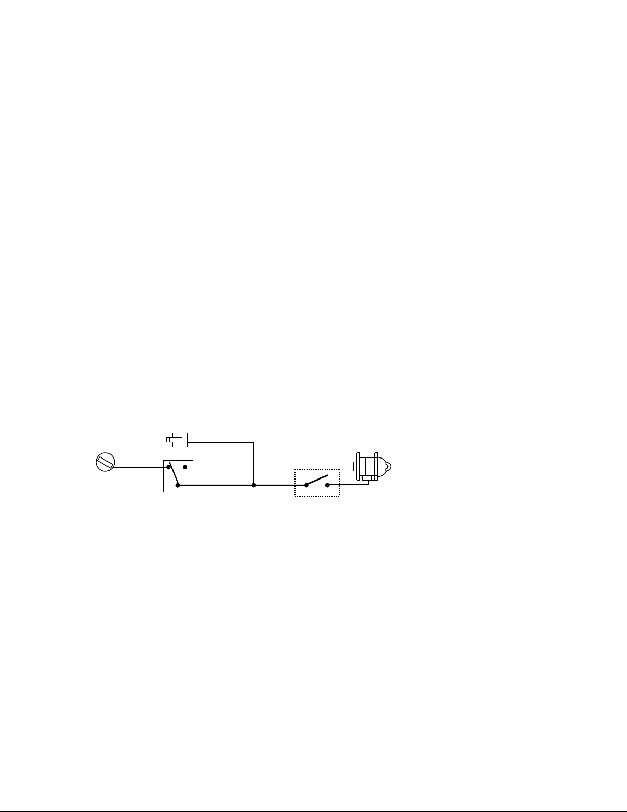
1. The optional “remote start toggle switch” can be added on to temporarily disable the Remote Start Device, it can
prevent the vehicle from being remote started accidentally. This feature is useful if the vehicle is being serviced
or stored in an enclosed area. To disable the remote start, move the optional remote start enable toggle switch
to the OFF position. To enable the remote start, move the optional remote start enable toggle switch to the ON
position.
2. If needed, this wire can connect to the PARK/NEUTRAL switch in the vehicle.
(See the TESTING YOUR INSTALLATION GUIDE)
IMPORTANT NOTE: This wire must have a “GROUND” to operate remote start.
Orange/White wire – 200mA Grounded Output when Disarmed - N.O. Disable
This wire will become grounded when the alarm is disarmed. The current capacity of this wire is 200mA. It can be
connected to optional Ignition disable relay / ECU disable relay / Fuel Pump disable relay.
Black/Green wire – (-) 200mA Timer Control Channel 4
Channel 4 Output (Factory default setting on momentary grounded)
This wire is built-in user-programmable timer output provides a ground through this wire. Press the transmitter
and buttons at the same time. You may program the built-in timer to send a ground signal for any time interval
between 1 second and 2 minutes. For instance, this timer output may be used to turn on the headlight with the
remote control. Also on certain BMW, Mercedes Benz, Jaguar and Volkswagen cars, you can use this unique
timed output to allow remote closure of all power window and sunroof without the need for an external module!
Black / Violet Wire– (-) 200mA Timer Control Channel 6
(See Alarm Feature Programming)
This wire is built-in user-programmable timer output provides a ground through this wire. Press the transmitter
and buttons at the same time. You may program the built-in timer to send a ground signal for any time
interval between 1 second and 2 minutes. For instance, this timer output may be used to turn on the headlight
with the remote control. Also on certain BMW, Mercedes Benz, Jaguar and Volkswagen cars, you can use this
unique timed output to allow remote closure of all power window and sunroof without the need for an external
module!
Blue wire – Ground Instant Trigger Input (Zone 2) –
This wire is the ground trigger input wire for hood and or trunk pin switches.
Pink wire – (-) 200mA Programmable Output 2 Steps Unlock Output (Factory default setting) (See Alarm Feature
Programming)
The 2 steps unlock feature will work for the most fully electronic door lock circuit. The vehicle must have an
electronic door lock switch (not the lock knob or key switch), which locks and unlocks all of vehicle's doors. When
wired for this feature, press the disarm (or unlock) button one time will disarm the alarm and unlock the driver's
door only. If, press disarm (or unlock) button two times within 3 seconds, the alarm will disarm and all doors will
unlock.
Factory Security Disarm Signal Output –
This wire is designed to disarm a factory installed security system. This wire sends a negative (-) 1 seconds
pulse upon a remote start and remote door unlocking. Some factory systems must be disarmed to allow remote
starting. In most cases, this wire may be connected directly to the factory alarm disarm wire. The correct wire will
show negative ground when the key is used to unlock the doors or trunk. This wire is usually found in the kick
panel area in the wiring harness coming into the car body from the door.
Start Status (Shock Sensor By-Pass Control) Output–
This wire is designed to by-pass shock sensor module. This wire will supply an output at all times the remote
start is operating plus an additional 3 seconds after the remote start unit turn off.
Key Sensor By-Pass Output –
This output is for a Key Sense wire by-pass that some Chrysler and Toyota vehicles need to activate remote
start. This wire comes on when remote start is activated and stays on for 20 seconds.
White / Black wire – Negative Safety Shut Down Input & Hood Trigger

E9 IN REV. A 10
The Yellow wire provides an instant
shutdown for the remote start,
whenever it is grounded. Connect the
wire to the hood pin switch previously
installed. This wire must be routed
though a grommet in the firewall and
connected to the hood pin switch. If
the pin switch is to be used with an
alarm system, connect this wire with
diode.
To: White/black wire /
Negative safety
To: Alarm instant
trigger Blue wire
Hood Pin Switch
Diode Diode
Important! This connection is a safety wire and must be connected as shown and tested as specifiled. Failure to
do so may result in personal injury or property damage. See detail of wiring in the following diagram. This wire may
also be used if the vehicle brake light circuit switches ground to the brake lights. An isolation diode must be used for
ground switched brake light circuits and must be connected to the output of the brake switch.
Orange wire – (-) 200mA Grounded Output When Armed –
This wire will become grounded when the alarm is armed. The current capacity of this wire is 200mA. This output
can control starter disable, when an intrusion is detected and the system is triggered. The vehicles prevent from
any unauthorized starting.
87
87a
85
30
86
IN4003 Diode
H2/15: Orange wire
from control module
“Start”
“On”
Purple wire
X
Cut
Yello wire
White wire
“Acc”
“Off”
Starter
H1/1 VIOLET wire (Starter output)
form Heavy Gauge wire harness
Red wire to
Ignition Switch
White / Violet wire – Positive Safety Shut Down Input – Must Be Installed
Yellow wire – (-) 200mA Ignition 3 Output –
This wire provides an instant shutdown
for the remote start, whenever it gets
+12volts. If the brake lights switch in
the vehicle switches +12 volts to the
brake light circuit, connect this wire to
the output side of the brake switch.
This will allow the remote start to shut
down if an attempt is made to operate
the vehicle without the key while
running under the control of the
remote start. In most vehicles, in order
to shift gear, the brake pedal must be
depressed. The brake input will in turn
cause the remote start unit to shut off.
See diagram.
+12 volts from fuse box
To White/Violet
wire
Brake light bulbs
Switch closes
When brake is
de
p
ress

E9 IN REV. A 11
This wire provides a 200mA (-) ground output that becomes active 4 seconds before the remote start unit initialize,
and remains grounded while running.
Ignition 3 output:
Some newer vehicles use a third
ignition wire which is required to start
and keep the vehicle’s engine running.
If this is the case, wire an IGN 3 relay
(not supplied) as shown below: Do not
connect any vehicle circuits together,
they are isolated for a reason.
Y
ellow Wire
87a
Ignition 3 Wire From
Ignition Key Switch
+ 12 V Constant
Fused 25A Capable
30
8586
87
Transponder interfacing using relay:
If the vehicle has a transponder system installed, you will need to by-pass the system while the vehicle is operating
under the control of the Remote Start Unit.
To do this:
1.You will need a transponder key that's already programmed to the vehicle.
2.Remove the trim around the ignition switch.
3.Wrap a thin (28 - 30awg) wire tightly around ignition switch 6 to 8 times and secure it.
4.About 6"down line make another loop of approximately 2"diameter.
5.Place the key inside this loop and secure it to the loop.
6. Connect on end of the (28 - 30awg) wire to pin (87) of the relay module.
7. Connect the other end of the loop wire to Pin (30) of relay module.
8. Connect the pin (86) of the relay module to the ignition wire from the ignition switch.
9. Connect the pin (85) of the relay module to the H10/11 yellow wire of 20-pin connector.
GM VATS KEY OVERRIDE:
If the vehicle has the General Motor VATS system installed, you will need to by-pass the system while the vehicle
is operating under the control of the Remote Start Unit. To do this:
1. Measure the resistance of the resistor pellet on the ignition key then select a resistor within 5% of the key’s
value.
2. Locate the pair of VATS wires in the vehicle, usually a pair of thin gauge wires running from the ignition switch to
the VATS control module.
3. Connect the YELLOW wire from Remote Start Unit to TERMINAL #85 of an external relay. Connect terminal
#86 of the relay to a fused +12 volt.
4. Cut (#1) wire (as shown), and connect the ignition switch side of the cut wire to terminal #87a of the relay.
Connect the other side of the (#1) wire to terminal #30.
5. Connect the previously seleted resistor from terminal #87 to the second(#2) wire (as shown).
Gray wire – (-) 200mA Channel 3 (Trunk) Output –
This will become a 1 second pulse ground by activate (button 3) on transmitter for two seconds, the current
capacity of this wire is 200 mA. This feature allows you to remote control trunk release or other electric device.
(Realay may be required).
Brown / White wire wire – (-) 200mA Programmable Output Horn Output –
This wire is provided to use the existing
vehicle's horn as the alarm system's
optional's warning audible device. It's a
transistorized low current output, and
should only be connected to the low
current ground output from the vehicle's
horn switch. When the system is
triggered, the horn will sound.
8586
87
87a
30
White/Blue
wire
To horn
+ 12 V
+12V Or Ground
Depending On System
Requirements
FUSE
Factory Security Rearm Signal Output –(See Alarm Feature Programming) –

E9 IN REV. A 12
This output is programmable. If programmed rearm a factory installed security system. This wire will supply a pulse
whenever the remote start times out or is shut dowm using the transmitter and remote door locking.
White / Blue wire – (-) Instant Start & Turn Off Input –
This wire activates and turns off the remote starter each time it sees a momentary ground signal. Normally used for
testing during installation or when activating the module from an after-market system.
White/Green wire – (-) Diesel Wait To Start Input
(See Start Feature Programming)
In diesel vehicles it is necessary to interface with the wire that on the WAIT-TO-START light in the dashboard. This
wire illuminates the bulb until the vehicle’s glow plugs are properly heated. When the light goes out the vehicle can
be started. This wire is always at the connector leading to the bulb in the dashboard. It can also be found at the
Engine Control Module (ECM) in many vehicles.
To test and determine the polarity of this wire:
1. Set your multi-meter to DCV or DC voltage (12V or 20V is fine).
2. Attach the (+) probe of the meter to (+) 12V.
3. Probe the wire that you suspect leads to the bulb with the (-) probe of the meter.
4. Turn the ignition switch to the ON position.
5. If the meter indicates 12 volts until the light goes out you have isolated the connect wire and the wire’s polarity is
negative (ground while the bulb is on).
6. If the meter reads zero volts until the light goes out and then reads 12 volts, you have isolated the connect wire
and the wire’s polarity is positive.
Connect this wire to the wire in the vehicle that sends the signal to turn on the WAIT-TO-START bulb in the
dashboard. In most diesels the wire is negative (ground turns on the bulb) and this wire can be directly connected
to the wire in the vehicle. If the vehicles use a positive wire (12V to turn the bulb) a relay must be used to change
the polarity.
(
-
)
Wait To Start Wire
Wait to Start
Indicator
Ignition (+
)
White/Green Wire
Wait To Start In
p
ut
87a
86
87
30
85
(
+
)
Wait To Start
Wait To Start
Indicator
White/Green Wire
Wait To Start In
p
ut
Black / Red Wire– (-) 200mA Timer Control Channel 5
(See Alarm Feature Programming) This wire is built-in user-programmable timer output provides a ground through
this wire. Press the transmitter and buttons at the same time. You may program the built-in timer to send a
ground signal for any time interval between 1 second and 2 minutes. For instance, this timer output may be used to
turn on the headlight with the remote control. Also on certain BMW, Mercedes Benz, Jaguar and Volkswagen cars,
you can use this unique timed output to allow remote closure of all power window and sunroof without the need for an
external module!

E9 IN REV. A 13
3 PIN DOOR LOCK CONNECTOR: (Maximum 500mA Output)
Blue Wire
Green Wire ( - ) Lock Pulse
( + ) Unlock Pulse
( - ) Unlock Pulse
(
+
)
Lock Pulse
Red(not used)
NEGATIVE TRIGGER DOOR LOCK SYSTEM
Red (not used)
Blue Wire Door Unlock
Green Wire Door Lock
Locking
Master
Switch
To Exi t i ng
Door Lock Relay
VACUUM OPERATED CENTRAL LOCKING
Green Wire
Blue Wire
+12V
XCut
Compressor
Door Switch
30
86
87a
85
87
30
86
87a
85
87
3 Pin
Plug To
Alarm
VACUUM OPERATED DOOR
LOCKING SYSTEM:
TYPICAL OF MERCEDES BENZ
AND AUDI.
Locate the wire under the driver's kick panel.
Use the voltmeter connecting to ground, verify
that you have the correct wire with the doors
unlocked, the voltmeter will receive "12 volts".
Lock the doors and the voltmeter will read
"0 volt". Move the alligator clip to +12V and
the voltmeter will receive "12 volts". Cut this
wire and make connections. Be sure to program
door lock timer to 3.5 seconds.
(See Alarn Feature B – 3 Programming.)
+12V
Master Door
Lock Switch
X
X
Splice
Splice
Cut the Existing
Lock Wire
To Door
Lock
Motor
To Slave Door
Lock switches
Cut the Existing
Unlock Wire
3 Pin Plug
To Alarm
5-WIRE ALTERNATING DOOR LOCK
30
86
87a
85
87
30
86
87a
85
87
Red +12V
Green Wire
Blue Wire
POSITIVE TRIGGER DOOR LOCK SYSTEM
Blue Wire Door lock
Green Wire Door Unlock
Locking
Master
Switch
To Exiting
Door Lock Relay
+ 12V
Red (not used)
2 STEP DOOR UNLOCK WIRE CONNECTION FOR
5 WIRE ALTERNATING DOOR LOCKS
+12V
Cut the Existing
Lock Wire
Cut Existing Unlock
X
Cut the Unlock Wire
Lock
Unlock
OEM Door Master Lock
OEM Slave
Door Lock
Switch
+12V
LockUnlock
To All Other
Door Lock
Motors
H2/13:
22-Pin
Plug
From
Alarm
Pink Wire
x
X
Blue Wire
OEM Driver’s
Door Lock Motor
+ 12V
85
86 87
87a
30
30
87
85
87a
86
30
87
85
87a
86
Green Wire
H9:
3 Pin
Plug
To
Alarm
Red +12V

E9 IN REV. A 14
2 STEP DOOR UNLOCK WIRE CONNECTION FOR
GROUND SWITCHED DOOR LOCKS
Cut Existing Unlock
X
LockUnlock
OEM Door Master Lock Switch
To All Other
Door Lock
Motors
White/Green
Wire
OEM
Door Lock
Motor
Existing Neg.
Lock Wire
Existing Neg.
Unlock Wire
86
30
85
87
87a
+ 12V
Green Wire
Door Lock
Blue Wire
Door Unlock OEM Door
Lock Relay
H2/13:
22-Pin
Plug
From
Alarm
H9:
3 Pin
Plug
To
Alarm
2 STEP DOOR UNLOCK WIRE CONNECTION FOR
POSITIVE SWITCHED DOOR LOCKS
Cut Existing Unlock
X
LockUnlock
OEM Door Master Lock Switch
To All Other
Door Lock
Motors
White/Green
Wire
OEM Driver's
Door Lock
Motor
+ 12V Existing Pos.
Lock Wire
Existing Pos.
Unlock Wire
30
87a
87
86 85
+12V
+ 12V
OEM Door
Lock Relay
86
30
85
87
87a
Green Wire
Door Unlock
Blue Wire Door Lock
H2/13:
22-Pin
Plug
From
A
larm
H9:
3 Pin
Plug
To
A
larm
PROGRAMMING
PROGRAMMING TRANSMITTER:
Note: This mode will only retain the last 4 remote transmitters programmed. If the transmitter memory is exceeded,
the security system will start deleting transmitters from memory in chronological order.
1. Turn the Ignition 'switch ‘OFF/ON’ 4 TIMES and stay in ON position.
“Within 15 seconds”.
2. Push the Valet switch 4 times and hold it on the 4th push until a long chirp is heard then release the valet switch.
You are now in the Transmitter programming mode.
3. Press and hold any button of the transmitter until the siren responds with a confirming chirp, indicating the signal
has been stored into memory.
4. If you have additional transmitters (up to 4) that need to be programmed, repeat step 3 for each transmitter.
Exit: Turn Ignition to 'OFF' position, or leave it for 15 seconds. 3 long chirps & 3 parking light flashes will confirm exit.
FEATURES PROGRAMMING:
ALARM FEATURE “A” PROGRAMMING:
1. Turn the Ignition 'switch ‘ON/OFF’ 3 TIMES and stay in OFF position.
2. Push the Valet switch 3 times (holding in on the 3rd push) until one long chirp is heard, then release the valet
switch. You are now in the Alarm feature “A” programming mode.
3. Press and release the transmitter button corresponding to the feature you want to program.
a. The siren chirps and LED pause will indicate previously setting.
b. The factory default settings is always [1] LED flash, [1] chirp.
4 Depress the transmitter button to change the feature. Simple keep re-depressing the transmitter button until the
system advances to your desired setting.
Press the transmitter button corresponding to the feature you want to program.
Press
Transmitter
Button
One Chirp /
LED one pulse
Factory Default
Setting
Two Chirps /
LED two pulses Three Chirps /
LED three pulses
Four Chirps /
LED four pulses
1Active arming Passive arming
without passive
door locking
Passive arming
with passive door
locking.
2Automatic Rearm
off Automatic
Rearm on
3Instant Door Ajar
error chirp
45 seconds
delay Door Ajar
error chirp.

E9 IN REV. A 15
4All Confirmation
chirps on
Siren
Confirmation
chirp on only
Horn
Confirmation
chirp on only
All Confirmation
chirps off
5+Panic with
Ignition off Panic with
Ignition on & off
Panic with
Ignition on & off.
Panic with No
time limit.
Without Panic
function.
6 + With Alarm
Function Without Alarm
Function
7+ Without Car-jack
mode
Active Car-jack
mode
Passive Car-jack
mode
8+With Dome light
turns on & off
after ignition on
& off (45 second
door by-pass)
With Dome light
turns on after
ignition off (45
second door
by-pass)
Without this
feature
9 + Lock/Arm &
Unlock/Disarm
Confirmation
Chirp
Lock/Arm
Confirmation
Only
Exit: Turn Ignition to 'ON' position, or leave it for 15 seconds. 3 long chirps & 3 parking light flashes will confirm exit.
45 seconds Delay Door Ajar Error Chirp:
This feature controls the error chirp that is generated if the system is armed with the door trigger active. This is useful
in a vehicle that has a long dome light delay after the door has been closed. If the system is armed before the dome
light has turned off, the security system will generate the door trigger error chirp. Use this feature to disable the door
open error chirp.
With Dome light turns on after ignition off:
Some vehicles turn on the dome light when ignition key is turned off. After remote start, with alarm on, a false alarm
may occur when the run time elapses and the dome light comes on. To prevent this from happing, program Alarm
Feature A-8 to “With Dome light turns on after ignition off (45 second door by-pass)”.
ALARM FEATURE “B” PROGRAMMING:
1 Turn the Ignition switch ‘ON/OFF’ 3 TIMES and stay in OFF position.
2 Push the Valet switch 4 times (holding in on the 4th push) until one long chirp is heard then release the valet
switch. You are now in the Alarm feature “B” programming mode.
3 Press and release the transmitter button corresponding to the feature you want to program.
Press
Transmitter
Button
One Chirp / LED
one pulse
Factory Default
Setting
Two Chirps /
LED two pulses Three Chirps /
LED three pulses
Four Chirps /
LED four pulses
1 Pathway
Illumination
Feature “off”
Parking light
turns “on” for
30- second
upon an unlock
signal
Parking light
turns “on” for 30-
second upon an
unlock signal &
10-second upon
a lock signal.
2 Ignition
controlled door
locks & unlocks
Ignition
controlled door
locks only
Ignition controlled
door unlocks only
Without ignition
controlled door
locks & unlocks
3 0.8 second door
lock & unlock 3.5 second door
lock & Unlock
0.8 second Lock,
0.35 second
Unlock
0.8 sec. dbl
Lock,
0.8 sec. dbl
Unlock

E9 IN REV. A 16
Five Chirps = 0.8 second Lock, double 0.8 second. Unlock
Six Chirps = Double 0.8 second Lock, 0.8 second Unlock
Seven Chirps = Door lock with “Comfort Feature”
Eight Chirps = DBI Two step unlock ( DBI ONLY )**
Nine chirps = DBI Unlock ALL doors ( DBI Only )**
**Select either of these options when using Encore Two Way Data Bus
Interface Only.
4 Brown Wire = (+)
Constant Siren
output
Brown Wire
=5-second (+)
pulse Siren
output
Brown Wire = (+)
Pulsing Output
(Relay required
for [-] Horn)
5 +3 Hours Timer Start 2 Hours Timer
Start
6 +
The Vehicle withou
t
Turbo
(The system Can
not be Arm with th
e
engine running)
The Vehicle with Turbo (The system Can be Arm with the
engine running)
The shock
sensor will be
by-passed upon
engine running.
(The engine will
run by itself after
the ignition is
turned off)
The shock sensor
by-pass three
minutes after
armed.
(The engine will
run by itself after
the ignition is
turned off)
Press and
buttons at
the same time
to control
Engine run time
for one minute
and the shock
sensor will be
by-passed upon
engine running.
Five chirps = Press and buttons at the same
time to control Engine run time for three minutes and the
shock sensor will be by-pass upon engine running.
Six chirps = Press and buttons at the same time
to control Engine run time for five minutes and the shock
sensor will be by-passed upon engine running.
7. +
Horn chirp Duration
Standard
Horn chirp
Duration
50 mS
Horn chirp
Duration
30 mS
Horn chirp
duration
10 mS
8 + Disable the out of
range check. Enable the out of
range check
Exit: Turn Ignition to 'ON' position, or leave it for 15 seconds. 3 long chirps & 3 parking light flashes will confirm exit.
Comfort Feature:
Some Vehicles have a special “COMFORT feature”. When you lock the door with the key, you can keep turning the
key in the door for about 5 to 7 seconds and the window will close directly. If your vehicle has the “COMFORT
feature” and you wish for the door to be locked and the window to be closed automatically at the same time by remote
control, you can set the alarm feature “B-3 “with comfort feature”.
ALARM FEATURE “C” PRORAMMING:
1 Turn the Ignition 'switch ‘ON/OFF’ 3 TIMES and stay in OFF position.

E9 IN REV. A 17
2 Push the Valet switch 5times (holding in on the 5th push) until one long chirp is heard then release the valet
switch. You are now in the Alarm feature “C” programming mode.
3 Press and release the transmitter button corresponding to the feature you want to program.
Press
Transmitter
Button
One Chirp / LED
one pulse
Factory Default
Setting
Two Chirps /
LED two pulses Three Chirps /
LED three pulses
Four Chirps / LED
four pulses
1H2/13 Pink Wire
=
Two step door
unlock output
H2/13 Pink Wire
= Factory
Security Disarm
Signal Output
H2/13 Pink Wire
= Start Status
Output
(Shock Sensor
Bypass)
H2/13 Pink Wire =
Start Status
Output
(Shock Sensor
Bypass 20 SEC)
2Brown / White
Wire = (-)
200mA Horn
Output
Brown / White
Wire = Factory
Security Rearm
Signal Output
3Fahrenheit
display for
Temperature
Celsius display
For temperature
4Override
Without
Password Pin
Code
Override With
Password Pin
Code
5+Black/Green
Wire Channel 4
Output =
Pulsed output
Black/Green
Wire Channel 4
Output =
Latched output
Black/Green
Wire Channel 4
Output =
Latched output
and reset with
ignition “on”
Black/Green
Wire Channel 4
Output = Timer
programming (set
to any interval
between 1 second
and 2 minutes.)
6+ Black / Red
Wire Channel 5
Output =
Pulse output
White/Red
Channel 5
Output =
Latched output
White/Red
Channel 5
Output =
Latched output
and reset with
ignition “on”
White/Red
Channel 5 Output
= Timer
programming (set
to any interval
between 1
second and 2
minutes.)
7 + Black / Violet
Wire Channel 6
Output =
Pulse output
Black / Violet
Wire Channel 6
Output =
Latched output
Black / Violet
Wire Channel 6
Output =
Latched output
and reset with
ignition “on”
Black / Violet
Wire Channel 6
Output = Timer
programming (set
to any interval
between 1 second
and 2 minutes.)
Exit: Turn Ignition to 'ON' position, or leave it for 15 seconds. 3 long chirps & 3 parking light flashes will confirm exit.
Channels 4 /5 /6 Timer Control Output Programming.
Enter:
1. Turn the Ignition 'switch ‘ON/OFF’ 3 TIMES and stay in OFF position.
2. Push the Valet switch 5 times (holding in on the 5th push) until one long chirp is heard then release the valet
switch. You are now in the Alarm feature ‘C’ programming mode.
Timer Program:
1. Press and release and buttons together 4 times, [4] LED flash, [4] siren/horn chirps to indicate that you
are in features “Channel 4 Timer Programming mode”.

E9 IN REV. A 18
2. Press and hold the valet switch, the timer will immediately start.
3. When the desired interval has passed, release the valet switch. 1 long chirp for confirmation. (Set to any
interval between 1 second and 2 minutes)
Note 1:
If your built-in timer controls window/sunroof closure in your car DO NOT change the timer setting! This requires
installer-only programming. Changing the value will adversely effect operation and may cause damage.
Note 2:
Latched output = The latched output selection will send a negative signal as soon as the Channel 4 button is
pressed and will continue until the button is pressed again.
Latched output / reset with ignition = The latched / reset with ignition output selection operates just like the latched
output but will reset or stop when the ignition is turned on.
Password Pin Code Setup:
Enter:
1. Turn the Ignition 'switch ‘ON/OFF’ 5 times and stay in OFF position.
2. Push the Valet switch 5 times (holding in on the 5th push) until one long chirp is heard then release the valet switch.
You are now in the Alarm feature “C” programming mode. You can program or delete the password pin code as
below:
Program:
1. Press and release the transmitter button twice, [2] LED flash, [2] siren/horn chirp to indicate that you are in
features “Password Pin Code Programming mode”.
2. Within 5 seconds, begin to enter your chosen first 9ths digit by pressing and releasing the valet Switch from 1 – 9
times.
3. Within 15 seconds of the last entered 9ths digit, turn the Ignition switch to “ON” position.
4. Within 15 seconds, enter your chosen second 9ths digit by pressing and releasing the valet Switch from 1 – 9
times.
5. Finish by turning the ignition switch to “OFF” position.
If the new password code was accepted, the unit would report back the newly entered code, by flashing the LED, first
indicating the first digit code has been memorized, pause and then the second digit code. The unit will report the new
code three times with a one-second’s pause between each code.
Note: If 15 seconds of inactivity expire, or if the ignition switch is turned “ON” for more then 5 seconds during of above
steps, the unit will revert back to the last successfully stored code. A [3] long chirps to confirm exit. Will revert back to
the last successfully stored code
Delete Password Pin Code / Override Without Password Pin Code (Factory default setting):
Within 15 seconds, press and hold the transmitter button for 3 seconds. One long chirp is heard to confirm
Deleted the Password Pin Code.
Example: To program the Password Code 92, you would;
Enter:
1. Turn the Ignition 'switch ‘ON/OFF’ 5 times and stay in OFF position.
2. Push the Valet switch 5 times (holding in on the 5th push) it until one long chirp is heard then release the valet
switch. You are now in the Alarm feature “C” programming mode.
Program:
1. Press and release the transmitter button twice, [2] LED flash, [2] siren/horn chirp to indicate you are in
features “Password pin code programming mode”.
2. Within 5 seconds, press and release the valet Switch 9 times.
3. Within 15 seconds of the last entered 9ths digit, turn the Ignition Switch to “ON” position.
4. Within 15 seconds press the valet Switch twice.
5. Turn the Ignition Switch to “OFF’ position.
You will note the LED flashing nine times, pause and then flash two times, pause. This pattern will be repeated three
times indicating the new code (92) has been accepted and stored in memory.
Exit: Press any button (except button) of the transmitter to exit the password pin set up mode.
REMOTE START FEATURE PROGRAM MODE.
START FEATURE “D” PROGRAMMING:

E9 IN REV. A 19
1. Turn the Ignition 'switch ‘ON/OFF’ 3 TIMES and stay in OFF position.
2. Push the Valet switch 6 times (holding in on the 6th push) until one long chirp is heard then release the valet
switch. You are now in the Start feature “D” programming mode.
3. Press and release the transmitter button corresponding to the feature you want to program.
Press
Transmitter
Button
One Chirp /
LED one pulse
Factory Default
Setting
Two Chirps /
LED two pulse Three Chirps /
LED three pulse
Four Chirps /
LED four pulse
1 +
Gasoline Engine
Diesel Engine
with
Wait-To-Start
Light
Diesel Engine
without
Wait-To-Start
Light
10 seconds
warm-up timer
Diesel Engine
without
Wait-To-Start
Light
15 seconds
warm-up timer
Diesel Engine
without
Wait-To-Start
Light
20 seconds
warm-up timer
2Factory alarm
disarm with
channel 3 on
Without this
feature
3Constant
parking light
output upon
Remote Start
Flashing parking
light output upon
Remote Start
420 minutes run
time 30 minutes run
time
10 minutes run
time
5 minutes run
time
5Door lock After
start(RUN)
Door un-lock
before start &
Lock after start
Door lock before
start and Door
lock after
shut-down
Without this
feature
6 +Temperature-
Control Starting
OFF
Temperature-Co
ntrol Starting
“ON”
0 ºF / -18 ºC
Temperature-Cont
rol Starting “ON”
15 ºF / -9 ºC
7 +
Press
button =
Activate Remote
Start.
Press -
button =
Activate Remote
Start.
8 +
White/ Blue
wire=
1 pulse activate
White/Blue
wire=
2 pulse activate
White/Blue
wire=
3 pulse activate
Exit: Turn Ignition to 'ON' position, or leave it for 15 seconds. 3 long chirps & 3 parking light flashes will confirm exit.
SAFE START (Child safety mode)
Factory defaults setting to press the button once to start the vehicle.
Programming this feature to eliminate an accidental remote start,
1. The user presses the transmitter buttons “twice” within 3 seconds to start the vehicle. or
START FEATURE “E” PROGRAMMING:
1. Turn the Ignition 'switch ‘ON/OFF’ 3 TIMES and stay in OFF position.
2. Push the Valet switch 7 times (holding in on the 7th push) until one long chirp is heard then release the valet
switch. You are now in the Start feature “E” programming mode.

E9 IN REV. A 20
3. Press and release the transmitter button corresponding to the feature you want to program.
Press
Transmitter
Button
One Chirp /
LED one pulse
Factory Default
Setting
Two Chirps /
LED two pulse Three Chirps /
LED three pulse
Four Chirps /
LED four pulse
1Exit the programming mode. (3 long chirp & 3 parking light flashes to
confirm this exit.)
2+ Voltage check
type (go to
3B)
Tachometer
Check type (3A)
Timer checking
type (go to 3B)
Data Bus
Interface
Mode**
3
A> RPM learning – see RPM Learning
B> Start Crank
Time:
0.6-second
0.8-second (2 chirps), 1.0-second (3 chirps), 1.2-second (4
chirps), 1.4-second (5 chirps), 1.6-second (6 chirps),
1.8-second (7 chirps), 2.0-second (8 chirps), 3.0-second (9
chirps), 4.0-second (10 chirps),
4Low check level Hi check level
5Start or Stop the system for TESTING & ADJUSTMENT
6 +
“TEST” Mode for
Zone 2 / instant
trigger & Zone 3 /
Door trigger
“TEST” Mode for
Zone 1 & Zone 4
(2 Stage Shock
Sensor)
7 + + 50 RPM
DBI ONLY No RPM learning
8 + - 50 RPM
DBI ONLY
No RPM
Learning or <
50RPM
9 + Automatic
Transmission Manual
Transmission
Exit: Press the button on the transmitter. 3 long chirps & 3 parking light flashes will confirm exit.
RPM LEARNING / TACHOMETER CHECKING TYPE
1. Turn the Ignition switch ‘ON/OFF’ 3 TIMES and stay in OFF position.
2. Push the Valet switch 7 times and hold it on the 7th push until a long chirp is hearing then release the valet
switch.
3. Press and release the transmitter and buttons at the same time once to set the “Tachometer Checking
Type”. [2] LED flash, [2] chirp to confirm this setting.
4. Press and release the transmitter button once, [2] LED flash, [2] chirp to indicate your are in features “RPM
Learning mode”.
5. Start the vehicle with the key. (While the engine is running, the parking & LED will flash, If don’t, please check
tachometer White/Blue wire connection.
6. Press and hold the valet switch for 2 seconds until a long chirp and the LED light constant for two seconds. The
RPM signal is learned.
7. Turns off the ignition switch to stop the engine running.
Once you complete step 7, you can adjust and test “Check Level” as below:
CHECK LEVEL PROGRAMMING: (TEST and ADJUST)
Other manuals for E9
1
Table of contents
Popular Automobile Accessories manuals by other brands

Whispbar
Whispbar K412W Fitting instructions

Autel
Autel MaxiCharger DC Fast Installation and operation manual

Whispbar
Whispbar K948W Fitting instructions

AGRI-COVER
AGRI-COVER SNOWSPORT 180 installation instructions

MadJax
MadJax CONVEX MIRROR 03-035 installation instructions

Brodit
Brodit ProClip 854210 manual