ENCORP iSAVER DPFC 165 Series User manual

OPERATING MANUAL
iSAVER DPFC 165 & 250 Series
‘The Eliminator’

– Page 2 –iSaver DPFC 165 & 250 Series Manual © 2021 Encorp Limited
TABLE OF CONTENTS
Section 1 Introduction 3
Section 2 Specications 6
Section 3 Installation 9
Section 4 Start-up 11
Section 5 Periodic Maintenance 25
Section 6 Troubleshooting 26
Section 7 Limited Warranty 32

– Page 3 –iSaver DPFC 165 & 250 Series Manual © 2021 Encorp Limited
1.
Introduction
iSaver Manual
This manual is intended as a general guide for the installation, commissioning, maintenance, and troubleshooting of
iSaver DPFC (Dynamic Power Factor Control) units.
This manual is written for qualied and licensed personnel exclusively. It is not a substitute for
professional training, safety and hazard procedures, or for handling industrial equipment. This
equipment must be installed as per applicable Canadian standards, Regulations and National
wiring rules. This is essential to avoid electric shock or re resulting in personal injury and damage
to equipment. Improper connection, handling, or installation may cause malfunction and potential
damage.
After going through the contents of this manual, if there are any doubts with regard to connectivity, commissioning,
operation or any other subject, it should be claried with the authorized representative of the supplier. Encorp does not
accept any responsibility for any damage (direct or indirect, consequential loss) incurred due to improper installation or
use of this unit(s).
Special Precautions
The following are mandatory safety measures when installing or using iSaver equipment:
• Measure the electrical parameters to ensure that the unit selected is appropriately sized and suitable.
• The standard iSaver units are designed for indoor use only and should be installed in a secure, dry environment.
• During transportation from the manufacturing unit to the customer’s premises, there is always a chance of
some connections within the unit becoming loose. It is mandatory to internally inspect the unit and tighten any
loose connections prior to installation and start-up.
• Depending on the environment and site conditions, the unit should be periodically inspected internally by a
qualied electrical technician.
Introduction
Majority of the loads in commercial establishments & industrial processes have very rapidly changing loads due to the
nature of their operation. These are usually complex loads highly inductive in nature as they use induction motor
drives, AC/DC drives, Arc Furnaces, Welders, CNC machines, Sodium Vapor / Metal Halide / Fluorescent lighting etc.
Though there are also some resistive and potentially some capacitive loads, the overall nature of this electrical load is
complex inductive load. This complex inductive load causes a poor lagging power factor. If this poor power factor is
left uncorrected, it draws excessive current (kVA) than the required amount to perform useful work. As Utilities have
to provide for the high demand which also eects their operations and distribution, they usually impose one or several
charges if the electrical eciency of the end user is lower than their contracted value. Depending on the tari structure
of the individual, this may increase their electricity bill and reduce available capacity substantially. As a consequence of
low eciency, the customer may get charged for high demand otake, reactive power charges, power factor penalties
etc. The increased current due to low eciency also eects the installed capacity utilization of the facility.
Using iSaver DPFC (Dynamic Power Factor Corrector), electrical eciency is enhanced almost to 100% and
consequently the monthly Electricity bill* is substantially reduced.

– Page 4 –iSaver DPFC 165 & 250 Series Manual © 2021 Encorp Limited
iSaver DPFC is fully automatic and based on the load requirement improves the power factor in real time to near unity
value which will result in a justied Return on Investment (ROI). In addition, it enables release of wasted capacity of
installed switch gear voltage uctuations due to high kVA draw, lowers heating of switch gear transformers and local
network. iSaver technology also compliments environmental sustainability by improving higher eciency.
* subject to customer tari structure
Features
• Your iSAVER uses a fully automatic Dynamic Controller (micro controller based Reactive Power regulator) for
accurate 4 Quadrant measurements that enable precise eciency enhancement.
• Software based logic driven for ecient selection of required compensation for fast and ecient operation.
• Control is dynamic and follows the load uctuations without any delay.
• Constant check and display of parameters on display panel. Display of key parameters like Voltage, Current,
kVA, PF enables end users, to utilize installed switch gear with higher eciency.
• Self-diagnostic feature enables on-line equipment performance verication which is extremely useful for
installation and maintenance.
• Built in a strong Floor mounted, powder coated nish to RAL 7035 with lockable secure enclosure.
• Equipment and components used are of high quality with conservative design parameters to increase longevity
of equipment.
• The internal design is fully accessible, and inspection/checks and any routine maintenance are logical and easy.
• Extremely easy to install with its own multi-indicator & practically no maintenance requirement. The Power and
Energy meter enable monitoring of actual consumption and other parameters.
• Short circuit and overload protection provided through MCB or MCCB.
• Over temperature protection is provided by shutting downing the Dynamic Switching (EDS) to provide
complete safety.
• Your iSAVER cooling and ventilation system is operated automatically only when required, minimizing the units
power consumption and power footprint.
• High Voltage Surge protection provided.
• Remote web based on-line performance monitoring option also available.
Benefits
• Total Power bill is reduced and installed power capacity improved based on the site operating conditions.
• Demand Charge and Power Factor penalty charges (additional charges) imposed by the Power Utility for low eciency
are signicantly reduced.
• Wastage and switch gear overburden caused by low eciency and harmonics causing heating losses are substantially
reduced.
• Load utilization capability of the facility is improved. Release of installed capacity can be as much as 25-35% and helps
avoid costly upgrades.
• Carbon footprint is reduced contributing to improved environmental sustain ability.
• Reduces total connected total power (kVA) requirement from utility. This results in cost avoidance for upgrades and
availability of additional power is almost instantaneous.
• The web-based performance monitoring feature of iSAVER enables online viewing and is useful to monitor the end
users load and any abnormal/faulty conditions remotely.

– Page 5 –iSaver DPFC 165 & 250 Series Manual © 2021 Encorp Limited
Application
Industries and commercial establishments with rapidly changing uctuating motorized equipment. Such examples are:
• AC/DC drives, Arc Furnaces, Welders, CNC machines, etc.
• Machine shops / Industrial manufacturing & Processing/ induction furnaces, etc.
• Multi-elevator systems, Escalators, CT scanners, MRI machines etc.
Selection of Equipment
iSaver DPFC Units are to be used in applications where the electrical loads are highly uctuating at very short
intervals. In such applications, the reactive power demand is almost instantaneous and the iSaver-DPFC is designed to
compensate within few milliseconds that requirement and maintain the Power Factor close to unity.
To select the correct size of iSaver DPFC, it is a good practice to measure the maximum reactive power requirement
as well as Voltage and Current Harmonics so that the correct size of equipment can be selected. It is envisaged that a
qualied and experienced professional will be consulted to assist in the selection process.
iSaver DPFC is designed to dynamically compensate that reactive power requirement in real time, reduce harmonics
signicantly and maintain the power quality with Power Factor close to unity.

– Page 6 –iSaver DPFC 165 & 250 Series Manual © 2021 Encorp Limited
2.
Specifications
Standard Specification for iSaver 160A
Model iSAVER-160A-3Ph
Voltage Input 600 VAC 60Hz
Supply Three Phase
Conguration 3 Phase – 4 Wire or 3 Wire
Current Rating 160A Nominal (165 kVAR)
Banks 1x27.5 + 1 x 55+ 1x82.5 kVAR
Minimum Correction Bank activation at Reactive load >19.5 kVAR
Sequence 1:2:3:3:3
Electrical Steps 06
Logic The unit is designed to operate in steps of 27.5 kVAR
Minimum Step 70% of the lowest Bank Capacity (19.5 kVAR)
Control Operation Controlled real time switching output based on load requirements.
Controller Micro controller based advanced electronic controller
Target Eciency > 98% (+/- 3%)
Energy Monitoring HMI Module with IP controller board
Displayed Data (RMS) V, I, kVA, kW, Hz, kWh, PF, kVAR, Hz, KVARh saved kVAh lag,THDv,THDi,
Deg. F
Display Meter Zero Voltage/current, Over Voltage/current, Over Under compensation
Under Volt, Excess VTHD & ITHD, iSAVER UNB Current
Diagnostics Phase & CT Sequence Indicator
Bank Protection Short circuit and Over-load protection (MCCB & MCB)
Construction Robust standalone metal enclosure (indoor application only)
Dimensions 1300 (H) x 1000 (W) x 750 (D)
Weight 375Kg
Mounting Floor Mounting with Foundation Bolts
Enclosure Powder coated corrosion resistant sheet steel enclosure (RAL 7035)
Transient protection Provided
Cable Entry Bottom and Right-side entry provision.

– Page 7 –iSaver DPFC 165 & 250 Series Manual © 2021 Encorp Limited
Standard Specification for iSaver 240A
Model iSAVER-240A-3Ph
Voltage Input 600 VAC 60Hz
Supply Three Phase
Conguration 3 Phase – 4 Wire or 3 Wire
Current Rating 240A Nominal (247.5 kVAR)
Banks 1x27.5 + 1 x 55+ 2x82.5 kVAR
Minimum Correction Bank activation at Reactive load >19.5 kVAR
Sequence 1:2:3:3:3
Electrical Steps 09
Logic The unit is designed to operate in steps of 27.5 kVAR
Minimum Step 70% of the lowest Bank Capacity (19.5 kVAR)
Control Operation Controlled real time switching output based on load requirements.
Controller Micro controller based advanced electronic controller
Target Eciency > 98% (+/- 3%)
Energy Monitoring HMI Module with IP controller board
Displayed Data (RMS) V, I, kVA, kW, Hz, kWh, PF, kVAR, Hz, KVARh saved kVAh lag,THDv, THDi,
Deg. F
Display Meter Zero Voltage/current, Over Voltage/current, Over Under compensation
Under Volt, Excess VTHD & ITHD, iSAVER UNB Current
Diagnostics Phase & CT Sequence Indicator Short circuit and Over-load protection
(MCCB & MCB)
Bank Protection Short circuit and Over-load protection (MCCB & MCB)
Construction Robust standalone metal enclosure (indoor application only)
Dimensions 1600 (H) x 1100 (W) x 750 (D)
Weight 475Kg
Mounting Floor Mounting with Foundation Bolts
Enclosure Powder coated corrosion resistant sheet steel enclosure (RAL 7035)
Transient protection Provided
Cable Entry Bottom and Right-side entry provision.

– Page 8 –iSaver DPFC 165 & 250 Series Manual © 2021 Encorp Limited
Suggested Connection Cable Size*
iSAVER Rating Rating of Main
Incoming Breaker
Suggested* Minimum Cable
rating (3.5 core)
Suggested* Cable Rating
(GND & Neutral)
iSAVER- 160A
iSAVER- 240A
250A
500A
212 KCmil Copper
Cable
400 KCmil Copper Cable
Per regulatory requirements
* Based on maximum current rating of the iSAVER incoming breakers

– Page 9 –iSaver DPFC 165 & 250 Series Manual © 2021 Encorp Limited
3.
Installation
Step by Step Connection
• This equipment must only be installed and serviced by qualied electrical personnel.
• Place the iSAVER rigidly in a secure, dry, suitable environment as close to the distribution panel as possible with
sucient space to connect the terminal section.
• Open the front and back panel door and visually inspect to ensure that nothing has become loose during
transportation and handling. If there is any evidence of damage or loose wires, repair or replace prior to
proceeding further.
• Select side or bottom entry terminal entry gland plates based on model and site requirement and disassemble
the selected gland plate by removing fasteners.
• Drill appropriate size hole for Cable entry and use suitable sized rubber Gourmet to ensure adequate safety of
cable insulation as well as to avoid entry of unwanted pests.
• All cables to the iSAVER should be routed through the rubber gourmet and the gland reinstalled.
• Turn down the power from the main power supply to the facility and ensure it is not energized and safe to
connect.
• Ensure the main breaker of the distribution board and iSAVER breakers are in an ‘OFF’ position.
• Select approved CT size based on the capacity of the Main Power supply breaker of the site. (Ex. If the breaker
size is 1250A, the CT to be used should also be rated as 1250/5 Amps, 600V AC). In some situations, the
physical installation clearance and bus bar size will determine the internal diameter of the CT coil to be used.
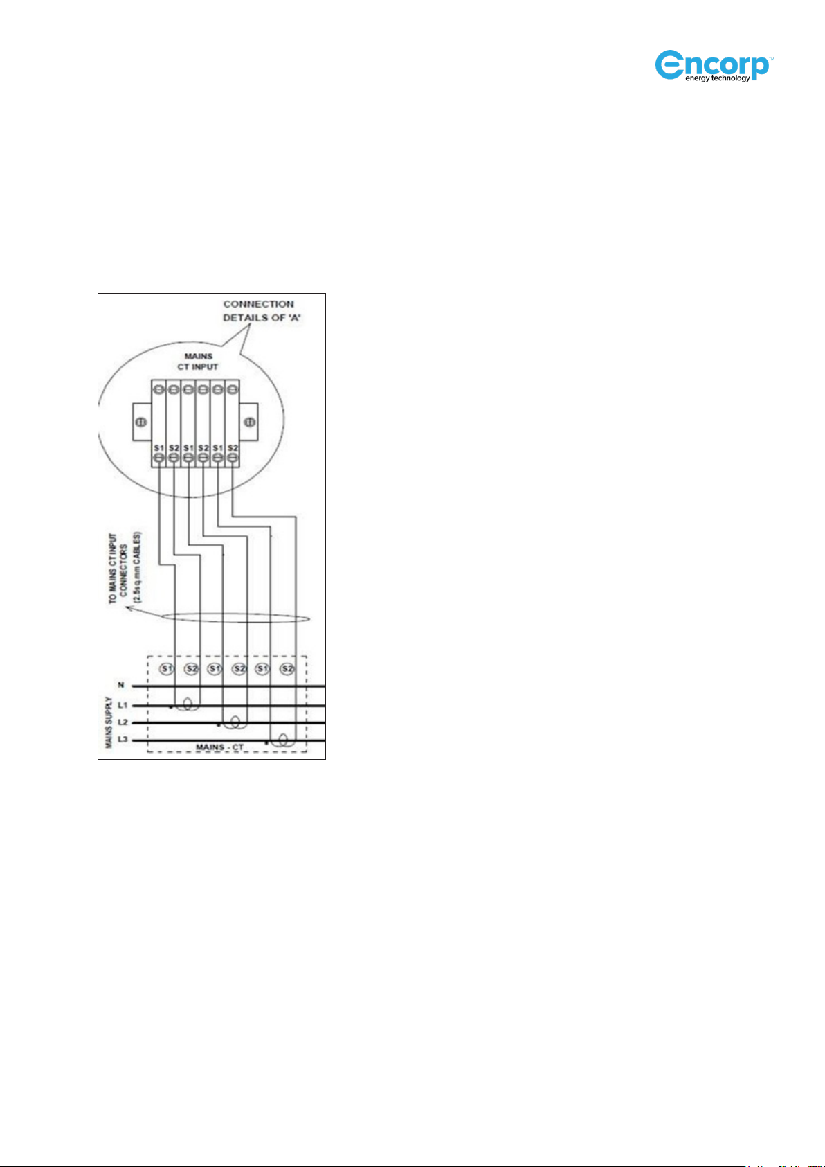
• The CT’s must be mounted on the main incomer bus bar/cable of L1, L2 and L3 phases with the correct
direction of the CT (check the current ow direction marked (P1 and P2) on the respective CT, P1 is the
current entry) as shown in the schematic.
This is critical to effectively operate the iSAVER
Legend: A. Power source cable and power ow
B. Mounting orientation indicator arrow
C. CT cables to iSaver CT connection
– Page 10 –iSaver DPFC 165 & 250 Series Manual © 2021 Encorp Limited
• It is critical that the External CT’s are positioned so that the total current (typically just after the main incomer
breaker) is measured (see connection schematic on page 8).
• The CT terminals (usually marked S1 & S2 and the direction of CT current ow is marked P1 & P2) must be
connected to the CT terminal block in the iSAVER unit in exactly the same sequence. Check the schematic for
further clarity. (Example: The R phase CT to be connected to the R phase in the terminal block at the S1 & S2
connection point).
External CT Connection to iSAVER Models
• Similarly, connect the incoming supply main cables in the right sequence. Use only an approved cable with
suitable sizing for connecting from the main distribution to the iSAVER MCCB as shown in the connection
schematic.
• Connect Ground for iSAVER with an approved cable of a suitable size.
• Color coding as per required electrical standards and codes is to be followed.
• It is extremely important to ensure that the external CT primary value is entered into the controller program
through HMI prior to startup to obtain the correct results and normal iSAVER operation.
Off-line Connection Verification
• Conduct a continuity test of each and every connection using a multi-meter to ensure that all the sequences
are correct as per the connection schematic (on page 8) and above procedure.
• If any of the sequence is found to be incorrect, iSAVER will not work properly. It is mandatory to correct the
connections.

– Page 11 –iSaver DPFC 165 & 250 Series Manual © 2021 Encorp Limited
4.
Start up
Start-up Procedure
The iSAVER has an advanced HMI display on the front iSaver panel providing the following displayed pages on the
home screen.
These icons provide the following functions:
Live Dashboard:
Touch this icon to view the live dashboard which displays mains and load parameters.
– Page 12 –iSaver DPFC 165 & 250 Series Manual © 2021 Encorp Limited
Online screens:
Six dierent pages can be displayed by touching the next screen icon .
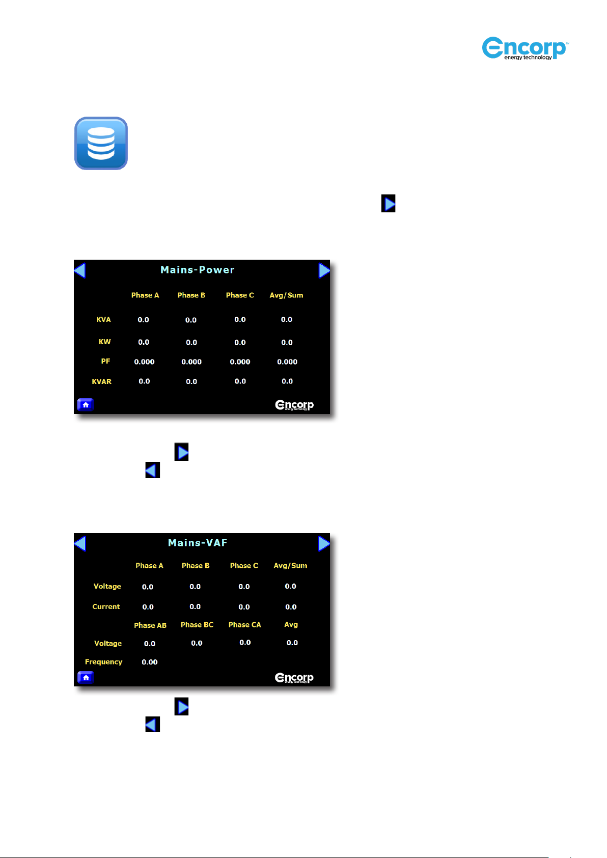
Mains Power:
Touch the arrow icon for the next screen to appear.
Touch this icon for the previous screen to appear.
Mains VAF Parameters:
Touch the arrow icon for the next screen to appear.
Touch this icon for the previous screen to appear.
Touch the online button to display the instant parameters.

– Page 13 –iSaver DPFC 165 & 250 Series Manual © 2021 Encorp Limited
Mains Energy:
Touch the arrow icon for the next screen to appear.
Touch this icon for the previous screen to appear.
Mains Power Quality:
Touch the arrow icon for the next screen to appear.
Touch this icon for the previous screen to appear.
Demand Parameters:
Touch the arrow icon for the next screen to appear.
Touch this icon for the previous screen to appear.
– Page 14 –iSaver DPFC 165 & 250 Series Manual © 2021 Encorp Limited
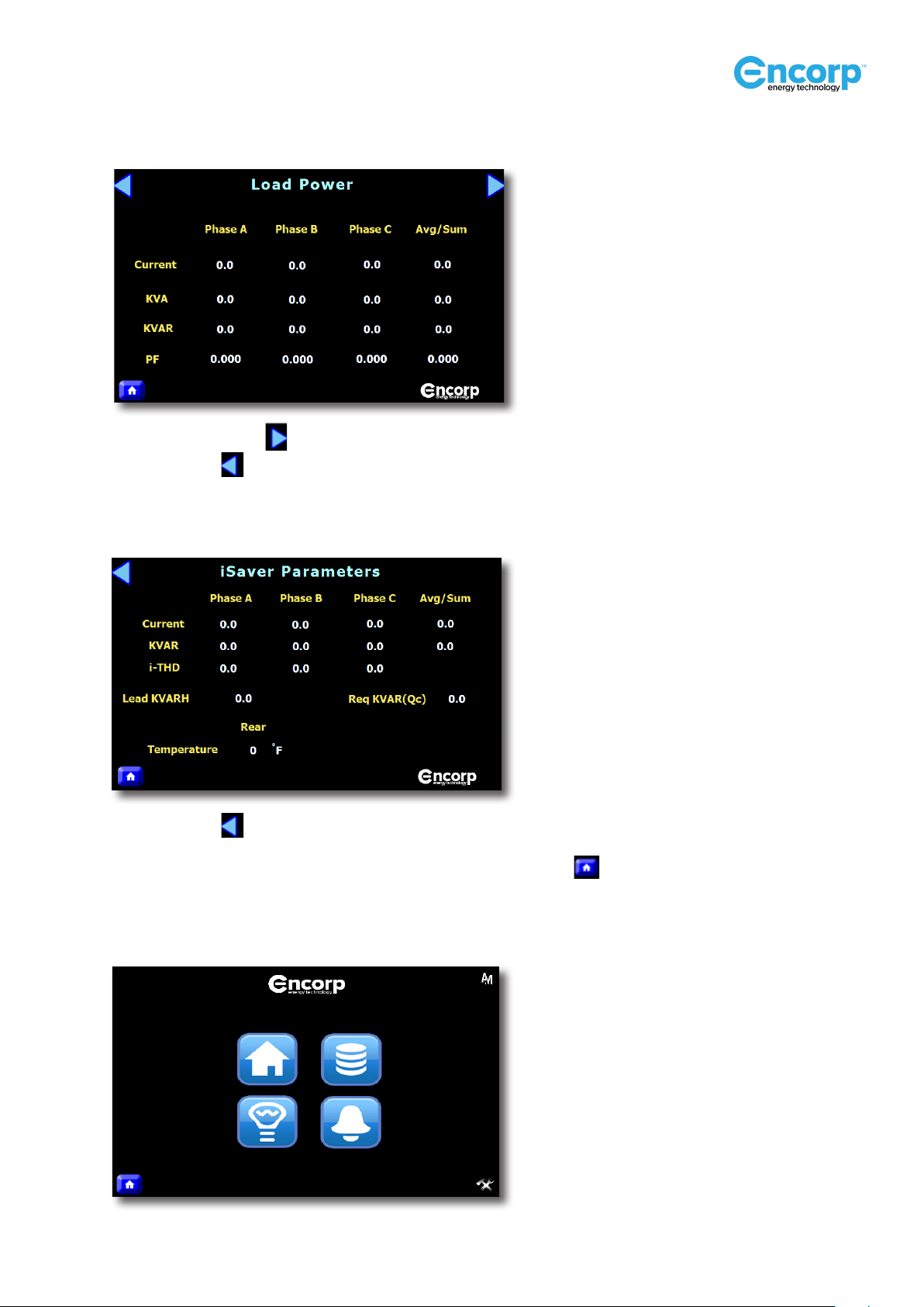
Load Parameters:
Touch the arrow icon for the next screen to appear.
Touch this icon for the previous screen to appear.
iSaver Parameters:
Touch this icon for the previous screen to appear.
To view the Savings, Alarm and Live Dashboard screens, touch the icon.
and the screen below will appear.

– Page 15 –iSaver DPFC 165 & 250 Series Manual © 2021 Encorp Limited
Savings Parameter:
Touch this icon and the Savings Parameter screen will appear.
To return to the HOME screen, touch this icon
Alarm Parameters:
Touch this icon and the Savings Parameter screen will appear.
To return to the HOME screen, touch this icon

– Page 16 –iSaver DPFC 165 & 250 Series Manual © 2021 Encorp Limited
Configuration Screen:
To return to the HOME screen, touch this icon . Touch this icon to view the
Conguration screen.
Password for 165KVAR machine: 165
Password for 247.5KVAR machine: 250
Touch the PASSWORD eld and a numeric
table will appear.

– Page 17 –iSaver DPFC 165 & 250 Series Manual © 2021 Encorp Limited
After entering the password select the ‘Enter’ button.
A Conguration screen as shown below will appear.
To change the numeric values, touch the existing eld value and a numeric table will appear. Enter the new
value and press the blue ‘Enter’ button. The new value will be stored in system memory.
Touch the arrow icon for the next ‘Conguration’ screen to appear.
To return to the HOME screen, touch this icon .
Touch any of the numeric elds to change the
values.

– Page 18 –iSaver DPFC 165 & 250 Series Manual © 2021 Encorp Limited
To change the numeric values, touch the existing eld value and a numeric table will appear. Enter the new
value and press the blue ‘Enter’ button. The new value will be stored in system memory.
Touch the arrow icon for the next screen to appear.
Touch this icon for the previous screen to appear.
To return to the HOME screen, touch this icon .
To change either the Calendar or Clock values,
you need to change each of the numeric elds
independently, i.e DD, MM, YY
To view the OPERATIONAL SEQUENCES, select
this eld.
To change the OPERATIONAL SEQUENCE
values, touch this eld and enter a value from
the numeric table that appear on the screen.

– Page 19 –iSaver DPFC 165 & 250 Series Manual © 2021 Encorp Limited
To reset the stored ‘ENERGY’ values, touch the green ENERGY PRESET button and the following screen will
appear.
If you wish to clear the cumulative energy value, press the green ‘YES’ button and the existing energy value will
be cleared. Click the ‘LOGOUT’ to display the live dashboard. This will display the machine performance.
Auto/manual Operation:
Select the blue HOME icon , then touch the AUTO/MANUAL icon in the top right corner of the
screen. The Auto/Manual screen will then appear.
Select the blue HOME icon , then touch the AUTO/MANUAL icon in the top right corner of the
screen. The Auto/Manual screen will then appear.

– Page 20 –iSaver DPFC 165 & 250 Series Manual © 2021 Encorp Limited
When the machine is in ‘AUTO’ mode, this screen will appear.
Manual Mode:
In this mode, you can check each bank. If you want to turn on the rst bank, click the BANK 1 ‘ON’ button.
The iSaver Current and iSaver KVAR values are also displayed below each bank. To turn o the bank, click
the OFF button. The Current and KVAR values will display a zero value, indicating that the bank is in OFF
mode.
• Conduct a nal visual check to ensure that it is safe to start commissioning the iSAVER (all connections
secured, tools removed, and safety checks completed).
• Turn on the breakers within the iSAVER unit.
• Close the iSAVER main access panel door and secure the panel locks with the key provided.
• Turn ON the main incomer MCCB located on the exterior front panel door of the iSAVER. It is
recommended that during this startup phase, some plant equipment is turned on to create some
electrical load. It is mandatory to have a minimum of 15% KVAR load (based on the size of equipment
used) to achieve an accurate startup result.
• The IP Motherboard will turn ON. This can be viewed on the HMI Live Dashboard.
This manual suits for next models
5
Table of contents
Other ENCORP Recording Equipment manuals


