ENCORP iSAVER DPFC 450 User manual

OPERATING MANUAL
iSAVER DPFC 450 & 650
‘The Eliminator’
Encorp Limited, 666 Great South Road, Level 3, Building 10, PO Box 17 506
Greenlane, Auckland 1546, New Zealand
tel: +649-928-7901 mobile. +6421-074-6273 email: info@encorp.co.nz www.encorp.co.nz

– Page 2 –
TABLE OF CONTENTS
Section 1 Introduction 3
Section 2 Specifications 6
Section 3 Installation 9
Section 4 Start-up 12
Section 5 Periodic Maintenance 20
Section 6 Troubleshooting 22
180419: DPFC 450-650 manual v5

– Page 3 –
1
Introduction
iSaver Manual
This manual is intended as a general guide for the installation, commissioning, maintenance, and troubleshooting of
iSaver DPFC (Dynamic Power Factor Control) units.
This manual is written for qualified and licensed personnel exclusively. It is not a substitute for
professional training, safety and hazard procedures, or for handling industrial equipment. This
equipment must be installed as per applicable Canadian standards, Regulations and National
wiring rules. This is essential to avoid electric shock or fire resulting in personal injury and damage
to equipment. Improper connection, handling, or installation may cause malfunction and potential
damage.
After going through the contents of this manual, if there are any doubts with regard to connectivity, commissioning,
operation or any other subject, it should be clarified with the authorized representative of the supplier. EnCorp
does not accept any responsibility for any damage (direct or indirect, consequential loss) incurred due to improper
installation or use of this unit(s).
Special Precautions
The following are mandatory safety measures when installing or using iSaver equipment:
• Measure the electrical parameters to ensure that the unit selected is appropriately sized and suitable.
• The standard iSaver units are designed for indoor use only and should be installed in a secure, dry environment.
• During transportation from the manufacturing unit to the customer’s premises, there is always a chance of
some connections within the unit becoming loose. It is mandatory to internally inspect the unit and tighten any
loose connections prior to installation and start-up.
• Depending on the environment and site conditions, the unit should be periodically inspected internally by a
qualified electrical technician.
Introduction
Majority of the loads in commercial establishments & industrial processes have very rapidly changing loads due to the
nature of their operation. These are usually complex loads highly inductive in nature as they use induction motor
drives, AC/DC drives, Arc Furnaces, Welders, CNC machines, Sodium Vapor / Metal Halide / Fluorescent lightings,
etc.
Though there are also some resistive and potentially some capacitive loads, the overall nature of this electrical load is
complex inductive load. This complex inductive load causes a poor lagging power factor. If this poor power factor is
left uncorrected, it draws excessive current (kVA) than the required amount to perform useful work. As Utilities have
to provide for the high demand which also eects their operations and distribution, they usually impose one or several
charges if the electrical eciency of the end user is lower than their contracted value. Depending on the tari structure
of the individual, this may increase their electricity bill and reduce available capacity substantially. As a consequence of
low eciency, the customer may get charged for high demand otake, reactive power charges, power factor penalties
etc. The increased current due to low eciency also eects the installed capacity utilization of the facility.
Using iSaver DPFC (Dynamic Power Factor Corrector), electrical eciency is enhanced almost to 100% and
consequently the monthly Electricity bill* is substantially reduced.

– Page 4 –
iSaver DPFC is fully automatic and based on the load requirement improves the power factor in real time to near unity
value which will result in a justified Return on Investment (ROI). In addition, it enables release of wasted capacity of
installed switchgear, voltage fluctuations due to high kVA draw, lowers heating of switchgear, transformers and local
network. iSaver technology also compliments environmental sustainability by improving higher eciency.
* subject to customer tari structure
Features
• The iSaver uses a fully automatic Encorp Dynamic Controller (Microcontroller based Reactive Power regulator)
for accurate 4 Quadrant measurements that enable precise eciency enhancement.
• Software based logic driven for ecient selection of required compensation for fast and ecient operation.
• Control is real time, dynamic and follows the load fluctuations without any delay.
• Constant check and display of parameters on display panel. Display of key parameters like Voltage, Current,
kVA, PF enables end users, to utilize installed switchgear with higher eciency.
• Self-diagnostic feature enables on-line equipment performance verification which is extremely useful for
installation and maintenance.
• Built in a strong Floor mounted, powder coated finish to RAL 7035 with lockable secure enclosure.
• Equipment and components used are of high quality with conservative design parameters to increase longevity
of equipment.
• The internal design is fully accessible and inspection/checks and any routine maintenance are logical and easy.
• Extremely easy to install with its own multi-indicator & practically no maintenance requirement. The Power
and Energy meter enable monitoring of actual consumption and other parameters.
• Short circuit and over load protection provided through MCB or MCCB.
• Over temperature protection is provided by shutting downing the Encorp Dynamic Switching manual (EDS) to
provide complete safety.
• iSaver cooling and ventilation system is operated automatically only when required minimizing the units power
consumption and power foot print.
• The modular design can be adapted for custom applications 150kVAr to 650kVAr
• High Voltage Surge protection provided (as option).
• Remote web based on-line performance monitoring option also available.
Benets
• Total Power Bill* is reduced based on the site operating conditions
• Demand Charge and Power Factor related charges (Penalty, additional charges imposed by utility for low
eciency etc.) are significantly reduced.
• Wastage and switchgear overburden caused by low eciency and harmonics causing heating losses are
substantially reduced.
• Load utilization capability of the facility is improved. Release of installed capacity can be as much as 25-35% and
helps avoid costly upgrades.
• Carbon foot print is reduced contributing to improved environmental sustainability.
• Reduces total connected total power (kVA) requirement from utility. This results in cost avoidance for
upgrades and availability of additional power is almost instantaneous.

– Page 5 –
• The web based performance monitoring feature of iSaver enables online viewing and is very useful to monitor
the end users load and any abnormal/faulty conditions remotely.
Application
Industries and commercial establishments with rapidly changing fluctuating motorized equipment. Such examples are:
• AC/DC drives, Arc Furnaces, Welders, CNC machines, etc.
• Machine shops / Industrial manufacturing & Processing/ induction furnaces, etc.
• Multi-Elevator systems, Escalators, CT scanners, MRI machines etc.
Selection of Equipment
iSaver DPFC Units are to be used in applications where the electrical loads are highly fluctuating at very short
intervals. In such applications, the reactive power demand is almost instantaneous and the iSaver-DPFC is designed to
compensate within few milliseconds that requirement and maintain the Power Factor close to unity.
To select the correct size of iSaver DPFC, it is a good practice to measure the maximum reactive power requirement
as well as Voltage and Current Harmonics so that the correct size of equipment can be selected. It is envisaged that a
qualified and experienced professional will be consulted to assist in the selection process.
iSaver DPFC is designed to dynamically compensate that reactive power requirement in real time, reduce harmonics
significantly and maintain the power quality with Power Factor close to unity.

– Page 6 –
2
Specications
Standard Specication for iSaver 450 DPFC
Model iSaver 450
Voltage Input 600 VAC 60Hz
Supply Three Phase
Configuration 3 Phase – 4 Wire
Rating 450 kVAr
Current Rating 450A
Banks 1x50 +(4x100) kVAr
Sequence 1:2:2:2:2
Logic The unit is designed to operate in steps of 50 kVAr
Minimum Step 70% of the lowest Bank Capacity (35 kVAr)
Control Operation Controlled real time switching output based on load requirements.
Controller Microcontroller based advanced electronic controller
Target Eciency > 98% (+/- 3%) for Canadian Voltage and frequency
iSaver Display 3 row crystal clear backlit LCD display of RMS values
Web Monitoring On Line iSaver parameters display (PF, kVA, kVAh, kW, kWh, kVAr,
kVArh, Hz, V-THD, I-THD, Status, Alarms, Time Integrated data.
Diagnostic feature iSaver internal key component functional analysis and status display
iSaver Monitor Displays main and ISaver (panel) parameters locally and remotely
DG operation Dedicated PF setting for DG operation
Displayed Data PF, kVA, kVAh, kW, kWh, kVAr, kVArh, Hz, V-THD, I-THD
Main Protection Short circuit and Over- load protection (MCCB 600A/50KA-3Pole)
Bank Protection Short circuit and Over- load protection (MCCB & MCB) and Thermal
safety trip(s). Unit automatically resumes operation once fault is
corrected.
Protection Thermostats operated over temperature protection of enclosure cham-
bers (Both Front and Capacitor Chamber), Harmonic Reactors and
Capacitors.
Construction Robust Standalone metal enclosure (indoor application only)
Dimensions 2000 (H) x 1100 (W) x 750 (D) mm
Weight 620Kg [± 3 %]
Mounting Floor Mounting with Foundation Bolts
Enclosure Powder coated corrosion resistant sheet steel enclosure (RAL 7035)
Transient protection Provided
Cable Entry Bottom and side entry provision.

– Page 7 –
Standard Specication for iSaver 650 DPFC
Model iSaver 650
Voltage Input 600 VAC 60Hz
Supply Three Phase
Configuration 3 Phase – 4 Wire
Rating 650 kVAr
Current Rating 650A
Banks 1x50 + (6x100) kVAr
Sequence 1:2:2:2:2
Logic The unit is designed to operate in steps of 50 kVAr
Minimum Step 70% of the lowest Bank Capacity (35 kVAr)
Control Operation Controlled real time switching output based on load requirements.
Controller Microcontroller based advanced electronic controller
Target Eciency > 98% (+/- 3%) for Canadian Voltage and frequency
iSaver Display 3 row crystal clear backlit LCD display of RMS values
Web Monitoring On Line iSaver parameters display (PF, kVA, kVAh, kW, kWh, kVAr,
kVArh, Hz, V-THD, I-THD, Status, Alarms, Time Integrated data.
Diagnostic feature iSaver internal key component functional analysis and status display
iSaver Monitor Displays main and ISaver (panel) parameters locally and remotely
DG operation Dedicated PF setting for DG operation
Displayed Data PF, kVA, kVAh, kW, kWh, kVAr, kVArh, Hz, V-THD, I-THD
Main Protection Short circuit and Over- load protection (MCCB 1000A/50KA-3Pole)
Bank Protection Short circuit and Over-load protection (MCCB & MCB) and Thermal
safety trip(s). Unit automatically resumes operation once fault is
corrected.
Protection Thermostats operated over temperature protection of enclosure cham-
bers (Both Front and Capacitor Chamber), Harmonic Reactors and
Capacitors.
Construction Robust Standalone metal enclosure (indoor application only)
Dimensions 1600 (H) x 1600 (W) x 800 (D) mm
Weight 750Kg [± 3 %]
Mounting Floor Mounting with Foundation Bolts
Enclosure Powder coated corrosion resistant sheet steel enclosure (RAL 7035)
Transient protection Provided
Cable Entry Top entry provision.

– Page 8 –
Connection Schematic for iSaver 450
Connection Schematic for iSaver 650
Suggested minimum connection cable size
iSaver Rating Rating of Main incoming
breaker
Suggested minimum cable
rating (3/3.5 core)
Suggested cable rating
(ground & neutral)*
iSaver 450 600A 2 set of 400 Kcmil) Per regulatory
requirements
iSaver 650 1000A 2 set of 800 Kcmil) Per regulatory
requirements
* Based on maximum current rating of the iSaver incoming breakers

– Page 9 –
3
Installation
Step by Step Connection
• This equipment must only be installed and serviced by qualified electrical personnel.
• Place the iSaver DPFC rigidly in a secure, dry, suitable environment as close to the distribution panel as possible
with sucient space to connect the terminal section.
• Open the front and back panel door and visually inspect to ensure that nothing has become loose during
transportation and handling. If there is any evidence of damage or loose wires, repair or replace prior to
proceeding further.
• Select side or top entry terminal entry gland plates based on model and site requirement and disassemble the
selected gland plate by removing fasteners.
• Drill appropriate size hole for Cable entry and use suitable sized rubber Gourmet to ensure adequate safety of
cable insulation as well as to avoid entry of unwanted pests.
• All cables to the iSaver-DPFC should be routed through the rubber gourmet and the gland reinstalled.
• Turn down the Power to the distribution board and ensure it is de-energized and safe to connect.
• Ensure the main breaker of distribution board and iSaver breakers are in ‘OFF’ position.
• Select approved CT size based on the capacity of the Main Power supply breaker of the site. (Ex.: If the
breaker size is 600A, the CT to be used should also be rated as 600/5 Amps, 600V AC). Sometimes, the
physical installation clearance and bus bar size etc. will determine the internal diameter of the CT coil to be
used.
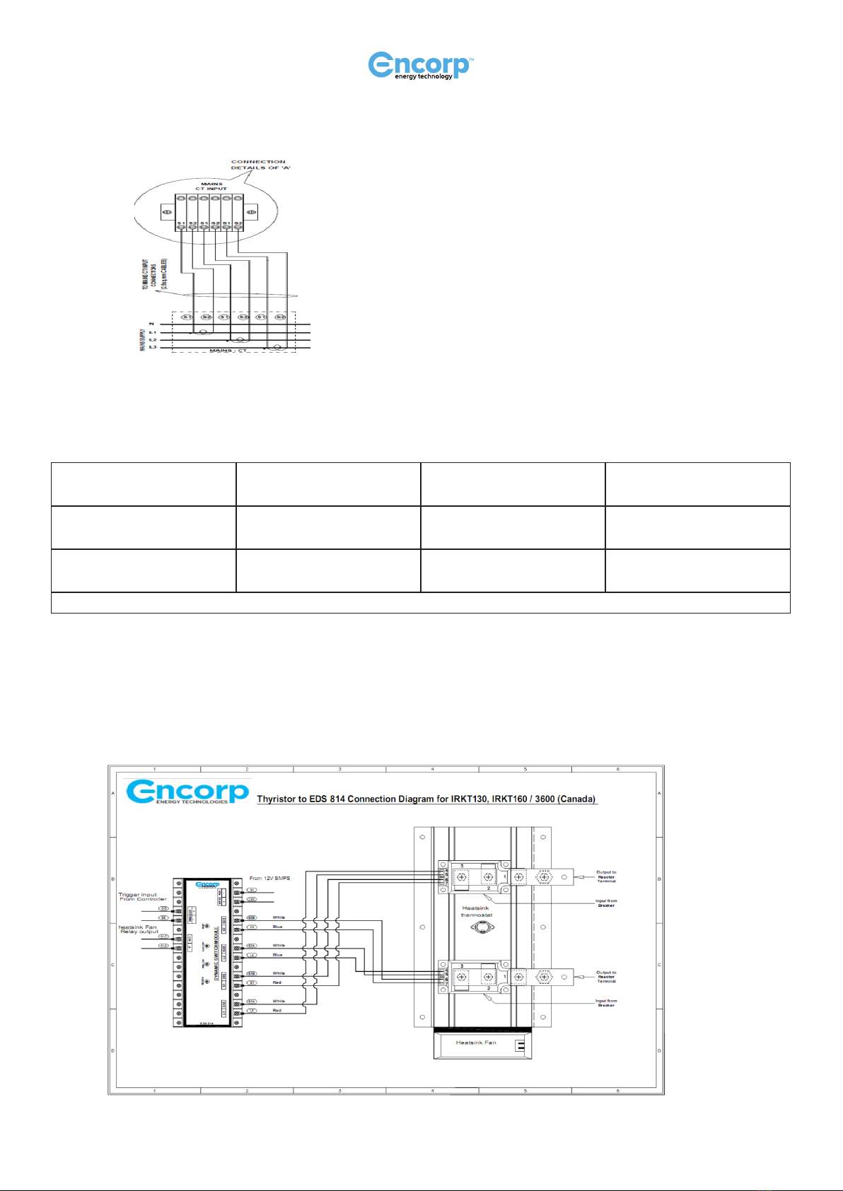
The CT’s have to be mounted on the main incomer bus bar/cable of L1, L2 and L3 phases with the correct direction of
the CT (check the current flow direction marked (P1 and P2) on the respective CT ,P1 is the current entry ) as shown
in the schematic. This is critical to eectively operate the iSaver.
It is critical that the External CT’s are positioned wherein the total current (typically just after the main incomer
breaker) to enable the measurement of the total current flowing through the main breaker (see schematic)
The CT terminals (usually marked S1 & S2 and the direction of CT current flow is marked P1 & P2) should be
connected to the CT terminal block in the iSaver unit in exactly the same sequence. Check the schematic for further
clarity. (Example: The R phase CT to be connected to the R phase in the terminal block at the S1 & S2 connection
point).
Legend: A. Power source cable and power flow
B. Mounting orientation indicator arrow
C. CT cables to iSaver CT connection
– Page 10 –
External CT Connection to iSaver DPFC
Similarly connect incoming supply main cables in the right sequence. Use approved cable with suitable sizing for connect
from the main distribution to the iSaver MCCB as shown in the connection schematic.
iSaver Rating Rating of Main incoming
breaker
Suggested minimum
cable rating (3/3.5 core)
Suggested cable rating
(ground & neutral)*
iSaver 450 600A 2 set of 400 Kcmil) Per regulatory
requirements
iSaver 650 1000A 2 set of 500 Kcmil) Per regulatory
requirements
* Based on maximum current rating of the iSaver incoming breakers
Connect Ground for iSaver-DPFC with approved cable with suitable sized
Color coding as per required standards and codes is to be followed.
It is extremely important to ensure that the external CT primary value is inserted in the controller to obtain correct
results and normal iSaver operation.

– Page 11 –
Off-line Connection Verication
Conduct a continuity test of each and every connection using a multi-meter to ensure that all the sequences are correct
as per the connection schematic and above procedure.
If any of the sequence is found to be incorrect, iSaver DPFC will not work properly. It is mandatory to correct the
connections.
– Page 12 –
4
Start up
Start-up Procedure
Conduct a final visual check to ensure that it is safe to start commissioning the iSaver (all connections secured, tools
removed, safety checks completed)
Turn on all breakers within the iSaver unit.
Close the iSaver main access panel door and secure the panel locks.
Turn ON the main incomer MCCB to the iSaver. It is recommended that during this start up phase, some plant
equipment is turned on to create some electrical load. It is mandatory to have a minimum of 15% KVAR load (based
on the size of equipment used) to have accurate startup results.
The iSaver controller will turn ON indicating Mains parameters.
iSaver Dynamic Controller
Setting the controller
By pressing
and
keys simultaneously for a few seconds, the program mode is selected. The display
shows the following screen;
EDC 814iSaver Dynamic Controller
MODE MORE
AUTO
MAN AL.ACK
A/M C1 C2 C3 C4 C5 C6 C7 C8 ALR
RXD
TXD
ENERGY TECHNOLOGIES
ncorp
C

– Page 13 –
PROG PASSWORD
/ / / /
In case it is desired to set a new password, press
key and the first slash (digit) will start blinking. (Please note
the factory default is 0000).
Now, select
key and each time it is pressed, the digits will change. Insert the default password and press
AL.ACK
key and the following program mode screen will appear.
PROGRAM MODE
Press
MODE
key and the following screen will appear
METERING SETUP
NEW PASSWORD
0000
To change to a new password
By using
and
keys, enter the new password and then press AL.ACK
key. The new password is
now set- record this securely as all future access to the controller will require this authorization password.
To change to Operating Voltage
By using keys, the following screen will appear.
METERING SETUP
OPERATING
VOLTAGE
0600
If the operating voltage is to be changed, press
key and the first slash (digit) will start blinking. Now, select
key and each time this is pressed, the digits will change. Insert the currosponding operating voltage and press

– Page 14 –
AL.ACK
key the new operating voltage is now set. The new operating voltage is now set.
To set Mains CT primary current
Press key to select select Mains CT primary Current value. (Ex. If a 1000/5A CT is used, then the primary
value should be set to 1000 in the four digit format as follows)
METERING SETUP
MAINS PRIMARY
CURRENT SET
1000
It is essential to set the Mains CT primary current value. To do this, press
key and the first slash (digit) will
start blinking. Now, select
key and when this is pressed, the digits will change. Insert the currosponding CT
primary value and press AL.ACK
key to save setting. The new mains primary current is now set.
To set iSaver CT primary current
Press key to select select iSaver CT primary Current value. (Ex. If a 400/5A CT is used, then the primary
value should be set to 400 in the four digit format as follows)
METERING SETUP
iSaver PRIMARY
CURRENT SET
0600
It is essential to set the iSaver CT primary current value. To do this, press
key and the first slash (digit) will
start blinking. Now, select
key and when this is pressed, the digits will change. Insert the currosponding CT
primary value and press AL.ACK
key to save. The new iSaver primary current value is now set.
To set the Clock
By using keys, the following screen will appear.

– Page 15 –
METERING SETUP
CLOCK
12:10:54
It is essential to set (RTC) clock to the correct local time. To do this, press
key and the first slash (digit) will
start blinking. Now, select
key and when this is pressed, the digits will change. Change to the correct time and
press AL.ACK
key the new Time is now set.
To set the Calendar
By using keys, the following screen will appear.
METERING SETUP
Calendar
20:04:2016
It is essential to set Calendar to the local date settings. To do so, press
key and the first slash (digit) will start
blinking. Now, select
key to change the digits to the correct date. Insert the present Date/Month/Year and
press AL.ACK
key the-new Date/Month/Year is now set.
To set Device ID
By using keys, the following screen will appear.
METERING SETUP
Device ID
001
In order to get on-line monitoring active, it is essential to set the device ID. Press
key and the first slash (digit)
will start blinking. Now, select
key and when this is pressed, the digits will change.
To set the Modem Device ID, as detailed on the back panel of the modem, insert the corresponding device ID and
press AL.ACK
key. The new device ID is now set.

– Page 16 –
To set display to Screen Power save mode
By using keys, the following screen will appear.
METERING SETUP
LCD POWER SAVE
Disable
If it is desired that the LCD back light is always turned On, select the disable mode by pressing
key and
press AL.ACK
key to save.
If it is desired to have the back light constantly On, select Enable by press
key and press AL.ACK
key. This
will set the LCD back light to be set in ON mode.
To set Energy Reset and Clear
By using keys, the following screen will appear.
METERING SETUP
Energy Reset?
If the meter needs to be reset, press AL.ACK
enter key, the following screen will appear.
METERING SETUP
ENERGY RESET
DONE
ENTERED
and the previous energy and average PF are reset to Zero.
Note: By doing this, we can see AVG. PF maintained by the panel from the installation.
All other remaining setting are done in the Factory based on the panel rating. Factory setting details in end of startup
procedure.
After completing the setting. Return back from the program mode by pressing
and
keys
simultaneously.

– Page 17 –
By using the selection key select the main PT seq and CT rev display page. (Refer iSaver controller operating
Manual for detailed operation).
iSaver Basic Diagnostic Features:
iSaver controller has the diagnostic features for PT sequence and CT Reversal indication. The following screen indicates
the correct sequence of connection.
MAINS
PT SEQ : ABC
CT REV : NIL
This screen check post-installation of CT and prior to start up will ensure voltage supply connected is in the correct
ABC Sequence and CT is connected in the correct polarity.
If there is any incorrect PT sequence, the display will show the following screen:
MAINS
PT SEQ : ACB
CT REV : NIL
Recheck the CT connections and installation and correct prior to start-up
In case the CT direction is incorrect and there is any CT polarity reversal, the display will show the following screen;
MAINS
PT SEQ : ABC
CT REV : B
This indicates that the B phase (L2) phase CT polarity is reversed. To correct inter change the S1 and S2. Recheck to
ensure it is correct prior to start-up.
Manual Parameters Display Selection
By using the and
MORE
key select various mains parameter like voltage, current, PF , KVA, KW & KVAR,
PF, THD etc.

– Page 18 –
You can verify the ISaver functionality in following manner
Press the
AUTO
MAN key, the LED on the controller panel marked A/M will glow indicating that the unit is now on
Manual Mode.
By pressing
key, gradually switch OFF all capacitor banks. After about one minute of switching o all banks,
note the mains reading in the respective iSaver (OFF) columns.
Parameters
iSaver (OFF) iSaver (ON)
A(L1) B(L2) C(L3) A(L1) B(L2) C(L3)
Voltage (L-L)
Current
PF
KW
KVA
KVAR
Once all the readings are noted, Press
AUTO
MAN key and change the controller from manual mode to auto mode. This
will be confirmed by the Manual LED light turning o and capacitor banks (C1, C2, C3 etc.) automatically starting to
turn on as required by the load demand.
After few minutes of stabilization when the panel readings stabilize, note the readings in iSaver (ON) columns. Using
this information, the eectiveness of the iSaver can be computed.
To verify the iSaver capacitor bank current on line using the controller, the iSaver current page display can be checked
through the following sequence;
Pressing
MODE
key, select iSaver parameter display page. The Display will show the following page;
iSAVER
CURRENT
A 50.0 B 50.0
C 50.0 ∑ 50.0
Now unit will operate automatically and the display panel will indicate all important parameters in a scrolling mode.
Metering Default Setup
Setting parameters iSaver 450
DPFC
iSaver 650
DPFC
New password 0000 0000
Operating voltage 600 600

– Page 19 –
Mains CT primary NOTE 1 NOTE 1
ISaver CT primary 600 1000
Clock NOTE 2 NOTE 2
Calendar NOTE 3 NOTE 3
Device ID NOTE 4 NOTE 4
LCD power saver DISABLED DISABLED
Energy reset sure NOTE 5 NOTE 5
NOTE 1: External mains CT primary value to be set.
NOTE 2: Local Time to be set
NOTE 3: Local Date to be set
NOTE 4: Corresponding communication ID to be set .if used, otherwise on setting required.
NOTE 5: To reset the energy and avg.PF when ever require. (It recommended during installation).
Default Control setup
Setting parameters iSaver 450 iSaver 650
EB PF Set point 1.00 1.00
DG PF Set point 0.80 0.80
Connection delay 02.0 02.0
Reconnection delay 005 005
NO. of Banks 5 7
1st bank value 50 50
Operating sequence 1:2:2:2:2 1:2:2:2:2
Default Alarm setup
Setting parameters iSaver 450 iSaver 650
Over voltage set(%) 110 110
Over current set (%) 120 120
Current THD (%) 30 30
Fan Temp Setup
Thermostat
Location
iSaver 450
Temp Range
in degree
Celsius
iSaver 650
Temp Range
in degree
Celsius
Front Door Fan 30 30
Back Door Fan 30 30
Front Temp Trip 50-55 50-55
Back Temp Trip 50-55 50-55

– Page 20 –
5.
Periodic Maintenance
Periodic Off-Line Maintenance Recommendation
Depending on the operating environment, a six-monthly internal inspection is highly recommended. During this
inspection, if any dust has accumulated, it can be vacuumed/removed. Verify integrity of connections to ensure
tightness.
Periodic On-Line Diagnostic Test
This is recommended to be done once in six months by the client or maintenance sta. The unit will continue to
operate normally automatically while the diagnostic test is conducted.
Press selection key
MODE
and select the iSaver current display page.
iSAVER
CURRENT
A 50.0 B 50.0
C 50.0 ∑ 50.0
Now press the key
AUTO
MAN
Auto/Man.
The LED marked A/M will glow indicating that the unit is now on Manual Mode.
Press
and the Capacitor will be switched OFF. Continue this till all the capacitors are switched OFF.
Press
key and the Capacitor bank will turn ON.
Check the corresponding change in capacitor bank current in iSaver current display page.
Verify the current value corresponding to the Bank ON indication (C1,C2,C3,C4,C5,C6,C7)
Press
and the Capacitors will switch OFF.
The above step is to be repeated for all the Banks and values verified as per the following default Current values table
below.
Once completed, return back to the normal mode by pressing
AUTO
MAN
key.
This manual suits for next models
1
Table of contents
Other ENCORP Recording Equipment manuals


