TREBING + HIMSTEDT SPI 3 User manual


Doc. Version 3.1 / December 2003
Dear customer
This online documentation is designed to help you with engineering, connecting up, con-
figuration and parameter setting of the SPI 3. Please feel free to contact our Technical
Support department if you need further help:
Trebing & Himstedt Prozessautomation GmbH & Co. KG
Technical Support Dept.
Wilhelm-Hennemann-Str. 13
D-19061 Schwerin, Germany
Telephone: +49-385-3 95 72-500
Telefax: +49-385-3 95 72-22
e-mail: suppo[email protected]
homepage: http://www.t-h.de
The information in this online documentation is the property of Trebing & Himstedt Pro-
zessautomation GmbH & Co. KG. This online documentation or extracts thereof may only
be duplicated or passed on to third parties following explicit written approval from Trebing
& Himstedt Prozessautomation GmbH & Co. KG. The right is reserved to make changes
to this online documentation and to the SPI 3 device at any time without prior notification.
All product names used in this manual are trademarks or otherwise protected by law,
even if this is not specifically mentioned.
SIMATIC®is a registered trademark of Siemens AG.

Table of contents
Introduction ........................................................................................................................... 2
Scope of delivery ...................................................................................................... 3
Documentation & Media kit (optional) ..................................................... 3
About this Online Documentation .............................................................................. 3
Safety notes .......................................................................................................................... 4
Safety notes for the planning stage ........................................................ 4
Safety notes for installation and operation of the SPI 3 .......................... 5
Overview of the SPI 3 ........................................................................................................... 6
Connections and interfaces .................................................................... 6
Mounting the device ................................................................................ 6
Operating elements ................................................................................ 6
Indicating elements ................................................................................. 7
Release ................................................................................................... 7
Mounting and connecting up the SPI 3 ...................................................................... 8
Attaching the SPI 3 to the top-hat rail ..................................................... 8
Connecting up the power feed ................................................................ 8
Connecting up to a fieldbus device with serial interface ......................... 8
Connecting up to the PROFIBUS ........................................................... 9
Setting the PROFIBUS address ............................................................. 9
Setting up the SPI 3 ............................................................................................................. 10
Configuring the SPI 3 .............................................................................................. 11
Setting parameters for the SPI 3 ............................................................................. 12
Installing the function blocks .................................................................................... 13
Checking the SPI 3 for correct operation ............................................................................. 14
Checking the SPI 3 power feed ............................................................................... 14
Checking the PROFIBUS communication ............................................................... 14
Checking the serial interface communication .......................................................... 14
Exchanging data using the SIMATIC FB’s .......................................................................... 15
Parameters for data transfer for SIMATIC S5 ......................................................... 16
Parameters for data transfer for SIMATIC S7 ......................................................... 18
Data consistency (only for S7) .............................................................. 20
Configuring the size of the data blocks (S5 and S7) ............................. 21
Sending data (S5 and S7) ....................................................................................... 21
Receiving data (S5 and S7) ..................................................................................... 22
Processing RK512 telegrams (S5 and S7) .............................................................. 23
Error diagnosis and remedies ............................................................................................. 24
Technical specifications ....................................................................................................... 26
Appendix .............................................................................................................................. 27
Creating a configuration telegram ........................................................................... 27
Creating a parameter telegram ................................................................................ 27
Standard bus-related parameters ......................................................... 27
SPI 3-specific parameters ..................................................................... 28
Glossary .............................................................................................................................. 30
General conditions ............................................................................................................... 37
Introduction ASCII | 3964R | RK512
2
Introduction
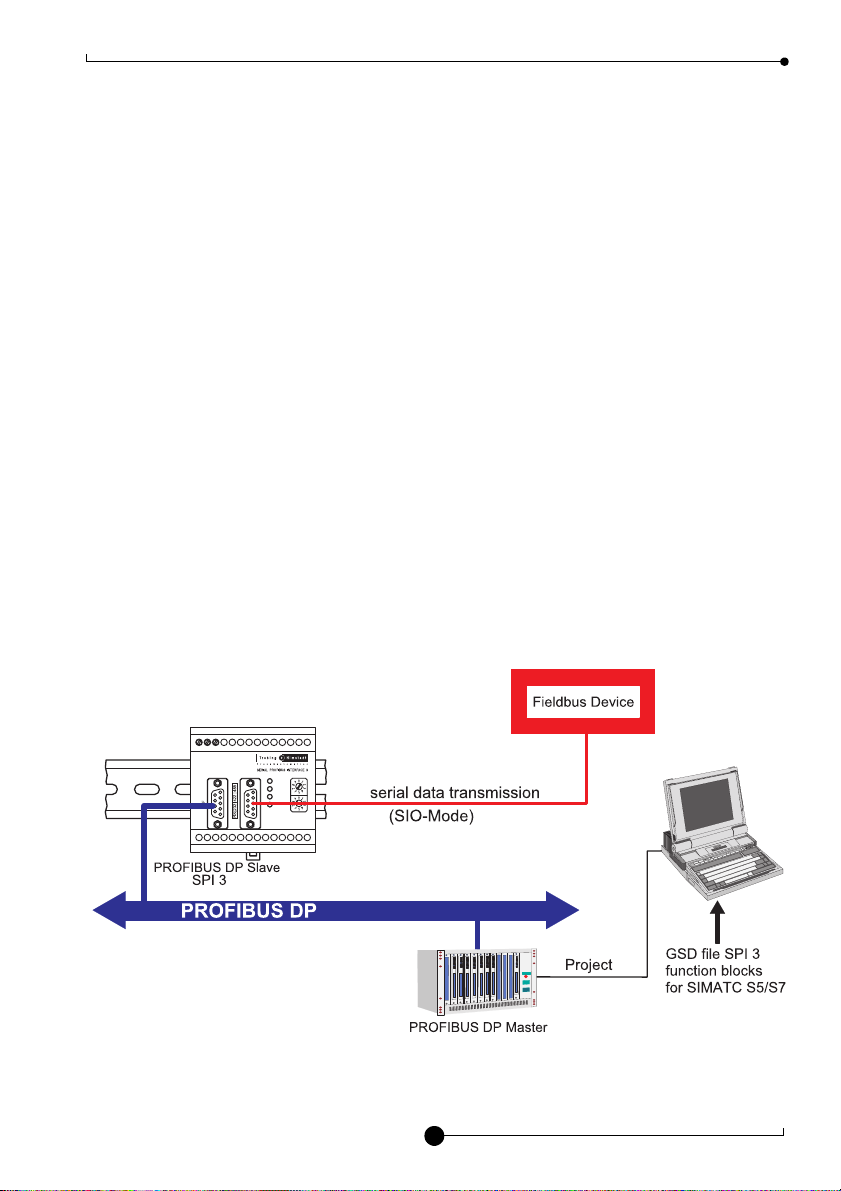
The SPI 3 (SERIAL-PROFIBUS-INTERFACE 3) allows a PROFIBUS-DP master to com-
municate with a fieldbus device with a serial interface. This allows the fieldbus device to
function as a real PROFIBUS station, whereby the SPI 3 converts the data to be ex-
changed between the PROFIBUS-DP master and the fieldbus device into a format which
is compatible with the other device.
Data is exchanged between the DP master and the SPI 3 in the form of telegrams or tele-
gram fragments through a data channel, the size of which can be configured to adapt it
to the telegram length and the size of the PLC I/O area. The data channel consists of a
send channel and a receive channel.
The SPI 3 is easy to install and configure and a separate program for configuration or pa-
rameter setting is not necessary. Configuration is done using the respective PROFIBUS-
DP master.
Features of the SPI 3:
· DP slave at up to 12 Mbit/s
· Serial baud rates up to 57.6 kbit/s
· Versions available for RS232, RS422 or RS485 serial interface
· Function blocks for SIMATIC S5/S7 (Included in Documentation & Media-Kit)
· Does not require special configuration software
· Simple and fast Integration in PROFIBUS-DP networks
· I/O range configurable from 2 to 64 data words
2 4 V
G N D
P E
RUN
P B
T X
R X
X
10
X
1
S t a t i o n
P R O F I B U S
( P L C )
Example for SPI 3 interface module overview

ASCII | 3964R | RK512 Introduction
3
Scope of delivery
Documentation & Media kit (optional)
The documentation & media kit contains this online documentation, function blocks for SI-
MATIC S5 and S7, GSD file and example files. You can download the documentation &
media kit (www.t-h.de). You need GSD file for the PLC project.
About this Online Documentation
Please read this online documentation before starting the installation work. It contains im-
portant information on planning your system, connecting up and configuring the SPI 3
and on parameter setting.
The online documentation uses the following keywords and symbols:
Danger!
Risk of injury to personnel due to electric shock.
Warning!
Risk of damage to equipment.
Note!
Indicates useful tips.
24V
GND
PE
RUN
PB
TX
RX
X
10
X
1
Station
RS|232|422|485
PROFIBUS
SPI 3 Quick start guide
SERIAL-PROFIBUS-INTERFACE
SPI 3
Quick reference guide
Doc. version 2.X

Safety notes ASCII | 3964R | RK512
4
Safety notes
Safety notes for the planning stage
Observe the general rules for PROFIBUS components when planning the SPI 3 installa-
tion.
Please observe the following to avoid risk to personnel and damage to equipment and to
ensure that the SPI 3 functions correctly:
Safety regulations – Observe the guidelines in the VDE 0100 regulations for hand-
ling electrical components,
– Observe the applicable safety and accident prevention reg-
ulations.
Assembly personnel The SPI 3 must only be installed or de-installed by qualified techni-
cal personnel with appropriate electrotechnical qualifications.
PROFIBUS standard Observe the guidelines in the PROFIBUS standard EN 50 170.
Bus cable Bus wiring should only take place using special screened, twisted
pair PROFIBUS cable. The high data transfer rates can only be
guaranteed with the correct cable type.
Cable lengths Refer to the manual for the DP master for information on maximum
cable lengths for PROFIBUS.
Terminating resistors Terminating resistors must be used if the SPI 3 is installed at the
beginning or end of the PROFIBUS cable segment. In this case,
you should use PROFIBUS connectors which contain an integrat-
ed terminating resistor. We recommend you to use connectors
from ERNI and Siemens. If the bus is incorrectly terminated, this
can lead to errors in data transfer or to damage to other stations on
the bus.
Bus connectors You should only use commercially available PROFIBUS connec-
tors for connecting the bus. We recommend you to use connectors
from ERNI and Siemens.
Cable screen Screened cables are less sensitive to interference due to electro-
magnetic fields. With screened cables, the interference currents
are led to ground through the screening rail, which is electrically
connected to the case. To ensure that the interference currents
which flow through the screening do not themselves interfere with
other devices, it is important to provide a low impedance connec-
tion to the protective ground. Observe the following rules for the
screens of the PROFIBUS cable and the serial interface cable:
– The braiding of the screening should have a degree of cov-
erage of more than 80 %.

ASCII | 3964R | RK512 Safety notes
5
– The screening should include a braided screen and should
not consist solely of foil screening, since the latter can be
easily damaged by cable tension and pressure.
– To ensure good immunity to interference at high frequencies
as well, the screening of the cable should be attached to the
screening rail at both ends of the cable.
Safety notes for installation and operation of the SPI 3
Please observe the following before connecting up the SPI 3 to avoid risk to personnel
and damage to equipment and to ensure that the SPI 3 functions correctly:
– The SPI 3 is designed as an interface between fieldbus devices with serial interfaces
and the PROFIBUS. Do not use the SPI 3 for any other purpose.
– The SPI 3 may only be installed or de-installed by qualified technical personnel with ap-
propriate electrotechnical qualifications. When connecting up the SPI 3, you must ob-
serve the guidelines in the VDE 0100 regulations for handling electrical equipment.
– Always mount the SPI 3 on a suitable top-hat rail.
– The cables used to connect up the SPI 3 should not apply any mechanical forces to the
device.
Danger!
Never open the case of the SPI 3 and do not make any modifications to the de-
vice.
Warning!
Small objects or liquids must not be allowed to enter the case of the SPI 3 (e.g.
through the ventilation slots) since this could damage the device.
Never cover up the ventilation slots in the case.
Large temperature differences between the storage location and installation site
can cause condensation to form within the case of the SPI 3, which can damage
the device. If large temperature differences are present, you should wait at least
3-4 hours after installing the SPI 3 and before switching on the power.

Overview of the SPI 3 ASCII | 3964R | RK512
6
Overview of the SPI 3
Connections and interfaces
– Power feed
· 24 V Screw terminal for external 24 V power supply
· GND Signal ground terminal
· PE Protective ground terminal
– PROFIBUS interface
– Serial interface (RS232, RS422 or RS485 see label on SPI 3)
Mounting the device
– Spring-loaded orange clip for releasing the SPI 3 from the top-hat rail
Operating elements
– Two rotary switches for setting the PROFIBUS address
· Switch for setting the tens value
· Switch for setting the units value
2 4 V
G N D
P E
R U N
PB
T X
R X
X
10
X
1
S t a t i o n
2
4
3
6
5
1
1
2
3
4
5

ASCII | 3964R | RK512 Overview of the SPI 3
7
Indicating elements
LEDs to indicate operating states (see »Error diagnosis and remedies« on page 24):
– RUN: lights continuously if supply voltage is present, flashes in case of errors
– PB: lights up if the SPI 3 has been configured by the master and is operational,
flashes in case of errors
– TX: flashes if data is being sent to the serial interface
– RX: flashes if data is being received from the serial interface
Release
The following information is indicated on the SPI 3 back-panel:
– Article No.
– Release No.
–SerialNo.
6
!$
R e l e a e 1 2
%
Overview of the SPI 3 ASCII | 3964R | RK512
8
Mounting and connecting up the SPI 3
Attaching the SPI 3 to the top-hat rail
– Hook the SPI 3 onto the top-hat rail and snap it into place.
In order to remove the SPI 3 from the top-hat rail, pull out the orange locking clip with
a suitable tool.
Connecting up the power feed
Danger!
Incorrect grounding of the SPI 3 can injure personnel and damage equipment.
Make sure that the SPI 3 is correctly grounded.
Warning! Although the SPI 3 is protected against polarity reversal, connecting
up the power feed with incorrect polarity for extended periods can damage the
device. Make sure that the power feed is connected with correct polarity.
– Connect the cables for 24 V power feed, ground and protective ground to the corre-
sponding screw terminals 24 V, GND and PE ( ).
Connecting up to a fieldbus device with serial interface
Note!
To ensure that the SPI 3 functions without errors, you should use a screened ca-
ble for connecting to the serial fieldbus device.
– Ensure that the Sub-D connector for the serial interface uses the pin assignments
shown in »Technical specifications« on page 26 (connect the cable screen to the case
of the sub-D connector).
– Attach the sub-D connector for the serial interface to the serial interface socket on
the SPI 3.
4
1
3

ASCII | 3964R | RK512 Overview of the SPI 3
9
Connecting up to the PROFIBUS
Note!
You should only use commercially available PROFIBUS connectors for con-
necting to the bus. We recommend you to use connectors from ERNI and Sie-
mens.
If the SPI 3 is installed at the beginning or end of the PROFIBUS cable segment,
you should use PROFIBUS connectors which contain an integrated terminating
resistor. We recommend you to use connectors from ERNI and Siemens.
To ensure that the SPI 3 functions without errors, you must ground the screen
of the PROFIBUS cable.
– Ensure that the PROFIBUS connector uses the pin assignments shown in »Technical
specifications« on page 26.
– Attach the PROFIBUS connector to the PROFIBUS interface socket on the SPI 3
and secure the connector with the retaining screws.
Setting the PROFIBUS address
Note!
The SPI 3 only updates its PROFIBUS address during a restart. Set the PROFI-
BUS address on the SPI 3 before switching on the power, or turn off the power
briefly after changing the PROFIBUS address.
PROFIBUS addresses 00 to 02 are reserved. You should only use addresses
between 03 and 99.
– The PROFIBUS address is set with the two rotary switches .
Example: In order to set the PROFIBUS address 68, turn the rotary switch for the 10’s to
6, and the rotary switch for the units to 8.
2
5
RUN
PB
TX
RX
X
10
X
1
Station

Setting up the SPI 3 ASCII | 3964R | RK512
10
Setting up the SPI 3
In order to set up the SPI 3, you need to configure it, set the parameters and install the
function blocks in your PLC programming software.
When configuring the SPI 3 from the DP master using a commercially-available PROFI-
BUS configurator program, refer to the on-line help for information on specifying the pa-
rameters. Since there are a large number of different PROFIBUS configurators on the
market, it is only possible to give a general overview of the process of configuration and
parameter setting:
– Start the PROFIBUS configurator on the DP master.
– Insert the diskette with the device database files (GSD) into the diskette drive of the
programming device (usually a PC).
– Load the SPI 3 GSD file THDP0091.GSD in the configurator.
– Configure the SPI 3 and set the parameters as described in the configurator’s online
help or user manual.
Note!
If you do not want to use a PROFIBUS configurator program, you need to create
your own configuration and/or parameter telegram. See »Creating a configura-
tion telegram« on page 27 for more information.

ASCII | 3964R | RK512 Setting up the SPI 3
11
Configuring the SPI 3
When configuring the SPI 3 with the PROFIBUS configurator, you will be prompted to
choose a firmware module from the menu. Choose a module from the following list ac-
cording to the required I/O area and data transfer protocol:
Note!
You should only configure one module for the SPI 3 device.
After configuring the SPI 3, you need to set the parameters. This is described in
»Setting parameters for the SPI 3« on page 12.
Module name I/O area Data transfer protocol
ASCII, 3964R, RK512 modules with simple parameters (for application in connection with FBs 100,
101, 103, 200, 201, 203 – control data stamp/mirror in byte 0 and byte 1)
MODUL_C1C1C101 2 words unstructured ASCII driver, 3964R, RK512
MODUL_C1C3C301 4 words unstructured ASCII driver, 3964R, RK512
MODUL_C1CFCF01 16 words unstructured ASCII driver, 3964R, RK512
MODUL_C1DFDF01 32 words unstructured ASCII driver, 3964R, RK512
MODUL_C1FFFF01 64 words unstructured ASCII driver, 3964R, RK512
ASCII, 3964R, RK512 modules with extended parameters (for application of release 12 an higher in
connection with FBs 100, 101, 103, 200, 201, 203 – control data stamp/mirror in byte 0 and byte 1)
ASCII_Prm+____2W_i/o 2 words unstructured ASCII driver, 3964R, RK512
ASCII_Prm+____4W_i/o 4 words unstructured ASCII driver, 3964R, RK512
ASCII_Prm+___16W_i/o 16 words unstructured ASCII driver, 3964R, RK512
ASCII_Prm+___32W_i/o 32 words unstructured ASCII driver, 3964R, RK512
ASCII_Prm+___64W_i/o 64 words unstructured ASCII driver, 3964R, RK512
Application-specific modules (only for application in connection with manufacturer-specific devices
and FBs – control data stamp/mirror in byte 0 and byte 1)
MODUL_C1414101______
MODUL_C1434301______
MODUL_C1858703______
MODUL_C1858C03______
MODUL_C1C2C303______
MODUL_82000004______
MODUL_C1CFCF07______
MODUL_C1DFDF07______
MODUL_C1FFFF07______

Setting up the SPI 3 ASCII | 3964R | RK512
12
Setting parameters for the SPI 3
When you configure the SPI 3 with the PROFIBUS configurator, you will be prompted to
choose the required parameters from a menu.
You can set the following parameters:
Choose the parameter values according to the serial fieldbus device you are using. If nec-
essary, refer to the descriptions of the required parameters in this manual.
Unstructured ASCII driver,3964R, RK512 see »SPI3-specificparameters« on page 28
Data transfer rate
Flags (only available in modules with extended parameters)
Handshake mode
ASCII code for the Xon character
(only required for Xon/Xoff handshake)
ASCII code for the Xoff character
(only required for Xon/Xoff handshake)
Parity
Character frame
Character timeout, response timeout
(see »Glossary« on page 30)
Data transfer mode
Priority
Start sign (only available in modules with extended parameters)
Stop sign (only available in modules with extended parameters)
Telegram length (only available in modules with extended parameters)

ASCII | 3964R | RK512 Setting up the SPI 3
13
Installing the function blocks
Note!
The function blocks (FB’s) are only suitable for SIMATIC S5 and S7 controllers.
If you want to use another type of controller, you will need to create new function
blocks yourself. See online documentation for more information.
You can either check the function blocks with the example project, or start with installing
the respective function blocks in your existing project. You only need to open the respec-
tive example project with the corresponding SPS programming software (Step 5 or Step
7):
1. Test example project (no connection of serial client required):
– Start SPS programming software.
– Open the respective PLC project.
– Adapt the applied SPS hardware (the exact name of the applied hardware in the ex-
ample project is to be found in the »readme_e.txt« file).
– Execute SPS Erase Program.
– Load the project into the SPS.
After successful loading and subsequent SPS RUN, the LEDs RUN and PB will light on
the SPI 3 (see also: »Checking the PROFIBUS communication« on page 14). The TX
LED flashes.
2. Load function blocks in an existing project:
– Start SPS programming software.
– Open the respective PLC project.
– Copy the FB into your SPS program. Enter FB command parameters (see »Parameters
for data transfer for SIMATIC S5 or … SIMATIC S7«).
– Execute further steps for your SPS program (integrate SPI 3 in hardware catalogue,
select module, adjust SPI 3-specific parameters, create DB, command FB etc.).
– Proceed further as described in the handbook or online support of the SPS pro-
gramming software.
The SPI 3 is ready for use after installing the function blocks.

Checking the SPI 3 for correct operation ASCII | 3964R | RK512
14
Checking the SPI 3 for correct operation
Several checks should be made before using the SPI 3 to transfer data.
Checking the SPI 3 power feed
– At this stage, do not attach either the PROFIBUS interface or the serial interface,
– switch on the power feed for the SPI 3.
The RUN LED should light continuously. If this is not the case, there is a fault in the 24 V
power feed. Refer to »Error diagnosis and remedies« on page 24 for details of how to lo-
cate the fault.
Checking the PROFIBUS communication
– Connect up the PROFIBUS interface cable,
– switch on the power feed for the SPI 3,
– start the DP master, which has been configured previously (see »example project Test«
on page 13).
The PB LED should light continuously. If this is not the case, there is an error in the
PROFIBUS communication. Refer to »Error diagnosis and remedies« on page 24 for de-
tails of how to locate the fault.
Checking the serial interface communication
– Connect up the PROFIBUS interface cable and the serial interface cable,
– switch on the power feed for the SPI 3,
– start the DP master, which has been configured previously,
– start the communication with the serial device.
The RUN LED should light continuously. If it does not light, or it only flashes, there is an
error in the communication with the serial device. Refer to »Error diagnosis and reme-
dies« on page 24 for details of how to locate the fault.
If no errors were detected, the SPI 3 is ready for use and you can use it for transferring
data.
The TX LED should flash when data is being transmitted over the serial interface and the
RX LED should flash when data is being received over the serial interface (see »Indicat-
ing elements« on page 7).

ASCII | 3964R | RK512 Exchanging data using the SIMATIC FB’s
15
Exchanging data using the SIMATIC FB’s
Asynchronous data exchange between the PLC and the SPI 3 is controlled by function
blocks (FB’s). The following FBs contains (you can download from the internet: www.t-
h.de):
For SIMATIC S5:
– FB200 is used to send data from the PLC to the SPI 3,
– FB201 is used to receive data from the SPI 3 in the PLC,
– FB203 is used to process RK512 telegrams (passive station), which are sent or re-
ceived by the SPI 3.
For SIMATIC S7:
– FB100 is used to send data from the PLC to the SPI 3,
– FB101 is used to receive data from the SPI 3 in the PLC,
– FB103 is used to process RK512 telegrams (passive station), which are sent or re-
ceived by the SPI 3.
Parameters must be set for each of the FB’s (you can also use the supplied example
project). The example project is intended as a guide. Don’t forget to set the length of the
I/O area in your program to match the module you have chosen (in example OB1: EA-L
is set for an I/O area of 4 data words in length).
Note!
The function blocks (FB’s) are only suitable for SIMATIC S5 and S7 controllers
(see online documentation).
In the case of SIMATIC S5 controllers, you may need to adapt the FB to the CPU
you are using (see the Step5 manuals). The FB’s are suitable for the CPU’s 922,
941 and 945. The example program is for the S5-115U/CPU941B, IM308-C.
The SIMATIC S7 example projects use an S7 315 2DP hardware; article No.
6ES7 315-2AF01-0AB0.
In the case of the data transfer protocol “unstructured ASCII driver” in combina-
tion with the RS485 serial interface, the SPI 3 sends the telegram which is re-
ceived from the DP master for the serial partner back to the DP master again.
The telegram can then be evaluated by the DP master and discarded.
Refer to »readme_e.txt« for further information

Exchanging data using the SIMATIC FB’s ASCII | 3964R | RK512
16
Parameters for data transfer for SIMATIC S5
The control data or user data to be exchanged is copied to a special PLC memory area
– the data block (DB) – from where the PLC writes the data to the SPI 3 through the DP
master. The data block consists of several data words, whereby data words 0 to 5 (DW0
to DW5) are reserved for internal use. User data always starts at DW6.
The following parameters must be specified when calling the FB’s. The tables indicate
which of the parameters are required for each of the FB’s:
Parameters for address information:
specify the location and length of the address array in the PLC address space.
Parameters for user data:
specify the location of the send/receive data blocks used for exchanging telegrams.
Parameters for processing RK512 telegrams:
specify the send and receive data blocks used for RK512 telegrams.
DW0 Internal use only
DW5 Internal use only
Start of user data DW6 User data
DW-L
DWX End of user data
Name Type Description / Function
present in:
FB200 FB201 FB203
A-A KF Starting address of send data area X X X
E-A KF Starting address of receive data area X X X
EA-L KF Length of I/O area of the SPI 3 (in bytes) X X X
Name Type Description / Function
present in:
FB200 FB201 FB203
DB B Data block for sending/receiving telegrams X X
DW-L W Length of data to send/receive (in bytes) X X
Name Type Description / Function
present in:
FB200 FB201 FB203
DB-Q B Data block for received RK512 telegrams X
DB-Z B Data block for RK512 telegrams to be sent X

ASCII | 3964R | RK512 Exchanging data using the SIMATIC FB’s
17
Parameter for return codes:
contain information on the status or processing results of the FB; also used to transfer
commands (e.g. reset) to the FB.
ANZW is used to convey information on the status of the currently executing data transfer
operation.
ANZW consists of 16 bits, of which bits 0, 1 and 4 are used for the coordination of a send
or receive operation as follows:
Bit 0 = 1 For FB200 and FB201: Operation is executing
For FB203: Telegram is being received
Bit 1 = 1 For FB200: Operation completed,
For FB201: Telegram has been received
For FB203: Telegram is being sent
Bit 4 = 1 Reset the operation
Set bit 4 to 1 to cancel the operation. Bit 4 is set to 0 again by the FB
when the operation has been reset.
Bit 2, 3, 5…15 internal use by the FB, do not change
Note!
FB203 for SIMATIC S5 uses the marker areas MW200 and MW202 for inter-
nal calculations. Do not use these market areas on your PLC program.
Name Type Description / Function
present in:
FB200 FB201 FB203
ANZW W Status word for data transfer status X X X

Exchanging data using the SIMATIC FB’s ASCII | 3964R | RK512
18
Parameters for data transfer for SIMATIC S7
The control data or user data to be exchanged is copied to a special PLC memory area
– the data block (DB) – from where the PLC writes the data to the SPI 3 through the DP
master. User data always starts at DW0.
The following parameters must be specified when calling the FB’s. The tables indicate
which of the parameters are required for each of the FB’s:
Parameters for address information:
specify the location and length of the address array in the PLC address space .
Parameters for user data:
specify the location of the send/receive data blocks used for exchanging telegrams .
Start of user data DW0 User data
Length
DWX End of user data
Name Type Description / function
present in:
FB100 FB101 FB103
A_Anfang POINTER Starting address of send data area
(z. B.: M2.0, A5.0, DB10.DBX8.0) XXX
E_Anfang POINTER Starting address of receive data area
(z. B.: M2.0, E5.0, DB10.DBX8.0) XXX
EA_Laenge INTEGER Length of I/O area of the SPI 3 (in bytes) X X X
Name Type Description / function
present in:
FB100 FB101 FB103
DB_Data Block_DB Data block for sending/receiving telegrams
(e.g.: DB37, DB38) XX
Laenge WORD Length of data to send/receive (in bytes)
(e.g.: Send: MB40, B#16#0A / Receive:
MB40, DB3.DBB5)
XX
Other manuals for SPI 3
4
This manual suits for next models
3
Table of contents
Other TREBING + HIMSTEDT Recording Equipment manuals


