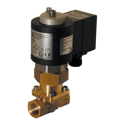
END ARMATUREN DG2D1 Installation instructions

Original Operating Manual
Pressure Actuated Valve
DG2D1
DG2D2
DG2D3, DA2D3, DL2D3, DM2D3,
DG3D3, DF3D
acc. to annex VI of the Directive 2006/42/EC
END-Armaturen GmbH & Co. KG
Oberbecksener Str. 78 · D-32547 Bad Oeynhausen · Telefon (05731) 7900-0 · Telefax (05731) 7900-199 · http://www.end.de

2 http://www.end.de DG2D - 07/2016
© END-Armaturen GmbH & Co. KG
All rights reserved. No part of this publication may be copied or published by means of printing,
photocopying, microfilm or otherwise without prior written consent of
END-Armaturen GmbH & Co.KG. This restriction also applies to the corresponding drawings.
END-Armaturen GmbH & Co. KG has the right to change parts of the valves at any time without
prior or direct notice to the client. The contents of this publication are subject to change without
notice.
This publication has been written with great care. However, END-Armaturen GmbH & Co. KG
cannot be held responsible, either for any errors occurirng in this publication or for their consequences.
The products are specified by the statements in this documentation; no assurance of the properties is given.
END-Armaturen GmbH & Co. KG
Oberbecksener Straße 78
D-32547 Bad Oeynhausen
Telefon: 05731 / 7900 - 0
Telefax: 05731 / 7900 - 199
Internet: http://www.end.de
E-Mail: [email protected]
Edition: 07/2016
Impressum

DG2D - 07/2016 http://www.end.de 3
Chapter Title .............................................................................................................................. Side
1 Foreword........................................................................................................................ 5
2 General advice.............................................................................................................. 6
2.1 Validity ............................................................................................................................ 6
2.2 Inward monitoring ........................................................................................................ 6
2.3 Complaints ..................................................................................................................... 6
2.4 Guarantee ...................................................................................................................... 6
2.5 Symbols and their signification.................................................................................. 7
3 Safety advice................................................................................................................. 7
3.1 Personal protection...................................................................................................... 7
3.1.1 Safety advice for mounting......................................................................................... 7
3.1.2 Safety advice for adjustment / starting..................................................................... 8
3.2 Device safety................................................................................................................. 9
4 Device descriptions................................................................................................... 10
4.1 Device description Pressure Actuated Valve........................................................ 10
4.2 Types of Pilot cylinder................................................................................................ 11
4.3 Device variants ........................................................................................................... 12
4.4 Name- plate ................................................................................................................. 13
4.5 Description of function .............................................................................................. 13
4.5.1 General ......................................................................................................................... 13
4.5.2 Normally close with flow direction.......................................................................... 14
4.5.3 Normally close against flow direction .................................................................... 15
4.5.4 Normally open against flow direction..................................................................... 15
4.5.5 Double acting .............................................................................................................. 15
4.5.6 Description of function: Pressure actuated valve (3/2-way)............................... 16
4.5.6.1 Split function................................................................................................................ 16
4.5.6.2 Mixing function ........................................................................................................... 16
4.6 Description of the options function ......................................................................... 17
4.6.1 Pilot valve..................................................................................................................... 17
4.6.2 Position indicator........................................................................................................ 17
4.6.2.1 Optical position indicator .......................................................................................... 17
4.6.2.2 Electrical position indicator ...................................................................................... 17
4.6.3 Manual override.......................................................................................................... 17
4.6.4 Stroke stop................................................................................................................... 17
5 Assembly Instructions............................................................................................... 18
5.1 Mounting of the valve (threaded connection) ....................................................... 19
5.2 Mounting of the valve (welded connection) .......................................................... 20
5.2.1 Disassembly of the valve top .................................................................................... 20
5.2.2 Welding of the body between two pipes................................................................ 21
5.2.3 Mounting of the valve top ......................................................................................... 22
5.3 Mounting of the valve (flanged valve)..................................................................... 23
5.4 Connection of the pilot medium................................................................................ 24
5.5 Mounting of pilot valve (Option).............................................................................. 25
5.5.1 Pneumatical installation of the pilot valve.............................................................. 26
5.5.2 Electrical installation of the pilot valve................................................................... 26
5.6 Electrical installation of a position indicator (Option) .......................................... 27
Contents

4 http://www.end.de DG2D - 07/2016
5.7 Disassembly................................................................................................................. 28
5.7.1 Electrical disassembly (Option)................................................................................ 28
5.7.2 Mechanical disassembly........................................................................................... 28
6. Adjustment /Starting.................................................................................................. 29
6.1 Stroke stop (Option).................................................................................................... 29
6.2 Starting ......................................................................................................................... 30
7 Emergency operation with manual override (Option)......................................... 30
8 Failure........................................................................................................................... 31
8.1 Failure causes ............................................................................................................. 31
9 Maintenance / Cleaning............................................................................................ 32
9.1 Maintenance ............................................................................................................... 32
9.2 Cleaning........................................................................................................................ 32
10 Technical data ............................................................................................................ 33
10.1 Technical data DG2D1xx ........................................................................................... 33
10.2 Technical data DG2D2xx ........................................................................................... 34
10.3 Technical data DG2D3xx, DA2D3xx, DL2D3xx, DM2D3xx .................................... 35
10.4 Technical data DG3D3xx ........................................................................................... 36
10.5 Technical data DF3Dxx .............................................................................................. 37
Contents

DG2D - 07/2016 http://www.end.de 5
1 Foreword
Dear customer,
Dear assembler / user,
these operating instructions are intended to give you the knowledge which is necessary for you
to be able to carry out the mounting and adjustment of an pressure actuated valve DG2D rapidly
and correctly.
Please read these instructions carefully and pay particular attention to the advice and warning
notes.
Only instructed and qualified mechanician should mount, adjust or maintain the pressure acting
valves.
The pressure acting valves will be deliver in several versions relative to
- pilot pressure and pressure range
- operations
- material
- connection type and connection size.
There are also several options available.
With accessories
- it can switch the pilot media
- it can indicate the position of the piston
- it can happen a manual override
- it can stop the stroke
The field of use of this valve is predominantly
- in food and drink industry
- in chemical installations
- in ventilation and blower construction
- in heating and air-conditioning technology
- in industrial fittings
- in water treatment etc.
If you have any questions in relation to the pressure acting valves DG2D, we shall be pleased to
answer them.
The telephone number will be found on the inside cover of these operation and installation
manual.
Yours
END-Armaturen GmbH & Co. KG
Foreword

6 http://www.end.de DG2D - 07/2016
2 General advice
2.1 Validity
These mounting and installation manual is valid for the standard version of the pressure actuated
valves DG2D1xx, DG2D2xx, DG2D3xx, DA2D3xx, DL2D3xx, DM2D3xx, DG3D3xx and DF3D On the
following pages the valves will be named DG2D .
2.2 Inward monitoring
Please check
- directly after delivery the valve for any transport damages and deficiencies
- with reference to the accompanying delivery note the number of parts.
Do not leave any parts in the package.
2.3 Complaints
Claims for replacement of goods which relate to transport damage can only be considered valid if
the delivery company is notified without delay.
In case of returns (because of transport damage/repairs), please make a damage protocol and
send the parts back to the manufacturer, if possible in the original packaging.
In case of return, please mention the following:
• Name and address of the consignee
• Stock-/ordering-/article-number
• Description of the defect
2.4 Guarantee
For our pressure actuated valve we give a guarantee period in accordance with the sales contract.
The warranty and guarantee rules of END-Armaturen GmbH & Co. KG are applicable.
General advice

DG2D - 07/2016 http://www.end.de 7
2.5 Symbols and their Signification
Paragraphs which are identified with this symbol contain very important advices; this also includes
advices for averting health risks.
Observe these paragraphs without fail!
Paragraphs which are identified with this symbol contain very important advices; this also includes
how to avoid damage to property.
Observe these paragraphs without fail!
This symbol indicates paragraphs which contain comments/advice or tips.
This bullet identifies the description of actions which you should carry out.
3. Safefty advice
Depending on the technical circumstances and the time under and at which the valve is mounted,
adjusted and commissioned, you must in each case take into account particular safety aspects!
If, for example, the valve works in an operational chemical plant, the potential hazards of commis-
sioning have another dimension from that when this is only being carried out for test purposes an
a „dry“ part of the plant in the assembly room.
Since we do not know the circumstances at the time of the mounting/adjustment/commissioning,
you may find advice on hazards in the following descriptions which are not relevant to you .
Please observe (only) the advice which applies to your situation!
The partly completed machinery must not be put into service until the final machinery into which
it is to be incorporated has been declared in conformity with the provisions of the Directive
2006/42/EC on machinery, where appropriate.
3.1. Personal protection
3.1.1. Safety advice for mounting
We wish to point out expressly that the mounting, the electrical installation and the adjustment
of the valves and the accessories must be carried out only by trained specialist personnel having
mechanical and electrical knowledge!
Switch off all the devices / machines / plant affected by mounting or repair.
If appropriate, isolate the devices / machines / plant from the mains.
Check (for example in chemical plants) whether the switching off of devices / machines / plant
will cause potential danger.
Symbols and their Signification

8 http://www.end.de DG2D - 07/2016
If appropriate, in the event of a fault in the valve (in a plant which is in operation) inform the
shift foreman / safety engineer or the works manager without delay about the fault, in order, for
example, to avoid an outflow / overflow of chemicals or the discharge of gases in good time by
means of suitable measures!
Before mounting or repair, relief the pressure from pneumatic / hydraulic devices / machines /
plant.
Empty the conduit from medium.
If necessary, set up warning signs in order to prevent the inadvertent starting up of the devices /
machines / plant.
Observe the respective relevant professional safety and accident prevention regulations when
carrying out the mounting / repair work.
Check the correct functioning of the safety equipment (for example the emergency push off but-
tons/ safety valves, etc)!
3.1.2 Safety advice for adjustment and starting
As a result of the starting (pneumatic or by hand) of a pressure actuated valve the flow of gases,
steam, liquids, etc. may be enabled or interrupted!
Satisfy yourself that, as the result of the starting or the test adjustments of the valve, no potential
hazards will be produced for the personnel or the environment!
If necessary, set up warning signs in order to prevent the inadvertent starting up or shutting down
of the devices / machines / plant.
By ending mounting check the correct function and the tightness of the valve.
Check the right position and correct function of mounted pilot valves and limit switches
Through suitable measures, prevent actuating links being trapped by moving actuating elements!
Check the right function of all safety devices (for example emergency off push buttons / safety
valves, etc. )!
Carry out the starting and the adjustments only in accordance with the instructions discribed in
this documentation!
When adjustments are being carried out on an opened and switch on (operational) limit switches
or pilot valves, there is the risk that live parts(230V AC~) can be touched!
Therefore the adjustment must be carried out only by the electrician or a person having adequate
training, who is aware of the potential hazard.
Safety advice

DG2D - 07/2016 http://www.end.de 9
Safety advice
3.2 Device safety
The pressure actuated valves
- is a quality product which is produced in accordance with the recognized industrial
regulations.
- left the manufacturer`s work in a perfect safety condition!
In order to maintain this condition, as installer / user you must carry out your task in accordance
with the descriptions in these instructions, technically correctly and with the greatest possible
precision!
We assume, as trained specialist you are having mechanical and electrical knowledge !
The valves must be used only for a purpose corresponding to its construction!
The valves must be used within the values specified in the technical data.
The mentioned data are experience values only and describe the general condition of our prod-
uct. They should be used as a guideline to evaluate the suitability of the non-concreate individual
case, but without any guarantee for the suitability given by END-Automation.
The final responsibility to proof and confirm the suitability of our products, for which we confirm
the perfect (faultless) quality by our delivery- and payment terms, lies in the dependance with
your constructive responsibility to the end-user.
Satisfy yourself that, as the result of the mounting, the starting or as a result of the test adjust-
ments on the valves, no potential hazards will be produced for devices / machines / plant!
Open the valve only to such an extant as described in this documentation!
Do not loose the locking ring of the pilot cylinder or don`t try to disassemble the pilot cylinder.
Do not mount the valve, start the valve or carry out any adjustments on it if the valve, the supply
lines or the part of the plant on which it is flange- mounted is damaged !
By ending mounting check the correct function and the tightness of the valve and check the cor-
rect function of the pilot valve and limit switches.

10 http://www.end.de DG2D - 07/2016
1 Valve body
2 Pilot cylinder
3 Screw joint
4 Cap
5 Connection
6 Pilot port
7 Flow direction indicator
8 Name-plate
9 Warning notice
4 Device descriptions
4.1 Device description pressure actuated valve
Fig. 4.1 -Device description, front / rear (figure shows DG2D3111025 without options)
Device descriptions
6
2
3
1
5
7
8
9
4
5

DG2D - 07/2016 http://www.end.de 11
Device description
Fig. 4.2 -Types of pilot cylinder, NC (witout options)
4.2 Types of pilot cylinder, NC
piston
Ø 80mm
piston
Ø 125mm
piston
Ø 50mm
piston
Ø 63mm
piston
Ø 32mm

12 http://www.end.de DG2D - 07/2016
Device variants
4.3 Device variants
The pressure actuated valves DG2D will be delivered in various variants.
The following table explains the composition of the article number to you. These article numbers
will be seen on the name plate:
For example: DG2D3116025/OS
Pressure actuated valve, Stainless steel / PTFE, normally close with the
flow direction, Stainless steel cylinder, G 1", with optical position indicator
3. Digit
Ways
2. Digit
Connection
1. Digit
Product
D= Pressure actuated
valve
G= B.S.P. thread
DIN ISO 228 T1
A= Welded connection
DIN 3293
L= Welded connection
ISO 4200
M = Welded connection
DIN 11850-R2
F = flanges acc. to DIN
2531 / 2533 / 2545
2= 2/2-ways
3= 3/2-ways
6. Digit
Seals material
seat / stem
1= brass
2= bronze
3= stainless steel
4= Carbon steel
5= GG (grey cast iron)
6= GGG (ductile iron)
7= Light alloy
8= Plastic
4. Digit
Operation
D= direct acting
5. Digit
Body material
1= PTFE / PTFE
2= PTFE / NBR
3= PTFE / FKM
4= PTFE / EPDM
5= NBR / PTFE
6= NBR / NBR
7= FKM / FKM
8= FKM / PTFE
brass cylinder
0= Ø 32 mm
1= Ø 50 mm
2= Ø 80 mm
3= Ø 125 mm
(aluminium alloy)
4= Ø 100 mm
stainless steel cylinder
5= Ø 50 mm
6= Ø 80 mm
7= Ø 125 mm
(aluminium alloy)
8= Ø 100 mm
9= Ø 32 mm
threaded flanged and welded
connection connection
006 = G
⅛
008 = G
¼
010 = G ⅜
015 = G
½DN 15
020 = G
¾DN 20
025 = G 1 DN 25
032 = G 1¼DN 32
040 = G
1½DN 40
050 = G 2 DN 50
065 = G
2½DN 65
080 = G
3 DN 80
100 = G 4 DN 100
125 = others sizes DN 125
150 = on request DN 150
ES = electric / mechanic position indicator
FL = flanged connection PN 16
HB = stroke stop
HN = manual override
HY = hygienic version
HO = stroke stop and optical position indicator
7. Digit
Operation
8. Digit
Piston- Ø
9. - 11. Digit
Connection
for 2/2-way-version:
1= Normally close
with the flow
direction
2= Normally close
against the flow
direction
3= Normally open
against flow
direction
4= Double acting
for 3/2-way-version:
1= split function
2= mixing function
12. - 20. Digit
Options
NI = inductive proximity limit switch
OF = free of oil and grease
OG = without valve body
OS = optical position indicator
NS = contactless position indicator (Reed- contact)
V= for vacuum
VD = for vacuum and pressure

DG2D - 07/2016 http://www.end.de 13
4.4 Name-plate
The pressure acting valves DG2D will be provided with a name- plate, which permits a definite
identification of the valves and shows the most important technical data to you. The name-plate
should not be displaced or changed.
Name-plate
Fig. 4.3 - Name- plate
Art.Nr. Article number of the valve (see also chapter 4. „device variants“)
Serie Order- or production-number
Betriebsdruck (PS) Max. admissible working pressure of the valve [bar]
Steuerdruck Recommend pilot pressure of the valve [bar]
Temperatur (TS) Temperature range of the valve
Größe (DN) Connecting size of the valve
Prüfdruck (PT) Testing pressure of the valve
Fluidgruppe Allowed fluid group of the valve
Herstellung Date of manufacturing
A potential fixed CE- mark relates to the Pressure Equipment Directive 2014/68/EU.
4.5 Description of function
4.5.1 General
A slanting seat in the valve body will be closed with or against the flow direction by a valve disk.
The valve disk is connected with the piston by a stem. It`s dynamical sealing and guidance hap-
pens by a screw joint between valve body and pilot cylinder. The slanting valve design renders a
highly flow rate by low dirtyness.
Pressure actuated valves would be actuated with the a piston by a neutral pilot media (air, water,
oil). It works in a pressure range from 0 bar up to the max. nominal pressure which you can see in
the pressure table. The flow direction is fixed and signed on the valve.
END-Armaturen GmbH & Co. KG
D-32547 Bad Oeynhausen
+49 (0)5731 - 7900-0 www.end.de
Art.Nr.: DG2D3122050
Serie: 220885
Betriebsdruck (PS): 8 bar
Steuerdruck: 6 bar
Temperatur (TS): -30°C ... +180°C
Größe (DN): 50 / G2"
Prüfdruck (PT): 60 bar
Fluidgruppe: 1
Herstellung: 14.02.2002
0062

14 http://www.end.de DG2D - 07/2016
The electrical control signal will be changed into the pressure media control by an optional avail-
able solenoid valve. The figure 4.4 shows a directly mounted solenoid valve type MGAG3D.
Description of function
© END-Armaturen GmbH & Co. KG
Fig. 4.4 -Description of function (Options: optical position indicator, solenoid valve)
valve closed valve opened by
copressed air
valve closing
by spring force
4.5.2 Normally close with the flow direction
The in neutral position closed valve obtains this function by a spring, which acts in close direction.
By feeding with compressed air the pilot pressure moves the piston against the spring and lift up
the valve disk from the seat. Therefore the valves open.
Because the valve closes with the flow direction, the nominal pressure supports the closing pro-
cess and seals the valve disk against the seat additionally. If the media flows through the valve
with a high speed the valve could close to fast and this could causes pressure shocks in the pipes.
We recommend the use of this operation mode only at gaseous media. The using of liquid media
could causes pressure shocks in the pipe.
Fig. 4.5 - Description of function - Normally close with the flow direction
© END-Armaturen GmbH & Co. KG

DG2D - 07/2016 http://www.end.de 15
Description of function
4.5.3 Normally close against the flow direction
The in neutral position closed valve obtains this function by a spring, which acts in close direction.
By feeding with compressed air the pilot pressure moves the piston against the spring and lift up
the valve disk from the seat. Therefore the valves open.
The valve closes against the flow direction only by the spring force. Therefore the valve closes
slowly and prevents pressure shocks in the pipes.
Fig. 4.6 - Description of function - Normally close against the flow direction
4.5.4 Normally open, close against the flow direction
The in neutral position opened valve obtains this function by springs mounted under the piston.
The valve closes against the flow direction only by the pilot pressure.
4.5.5 Double acting
The valve closes against the flow direction only by the pilot pressure. The valve opens with the flow
direction only by the pilot pressure.
Fig. 4.7 - Description of function - Normally open, close against flow direction; Double acting
© END-Armaturen GmbH & Co. KG
© END-Armaturen GmbH & Co. KG

16 http://www.end.de DG2D - 07/2016
Description of function
Fig. 4.9 - Description of function: mixing function
© END-Armaturen GmbH & Co. KG
A P1
P2
A P1
P2
Mischfunktion
A
P1P2
4.5.6.2 Mixing function
At this function the valve will be pressurized by two ports (P1 / P2). In case of the position of the
piston the medium flows from one of the two inlet ports to the outlet port. (P1►A / P2►A)
4.5.6 Description of function: Pressure actuated valve (3/2-way)
A straight seat in the valve body will be closed with or against the flow direction by a valve disk.
The valve disk is connected with the piston by a stem. It`s dynamical sealing and guidance hap-
pens by a screw joint between valve body and pilot cylinder. The 3/2-way pressure actuated valve
renders two functions: 1. split function
2. mixing function
Pressure actuated valves would be actuated wit a piston by a neutral pilot media (air, water, oil).
It works in a pressure range from 0 bar up to the max. nominal pressure which you can see in the
pressure table. The flow direction is fixed and signed on the valve.
4.5.6.1 Split function
At this function the valve will be pressurized by the inlet port P. In case of the position of the piston
the medium flows from the inlet port to one of the outlet ports. (P►A / P►B)
Fig. 4.8 - Description of function: split function
P B
A
P B
A
Aufteilfunktion
B A
P
split-function
mixing-function

DG2D - 07/2016 http://www.end.de 17
4.6 Description of options function
4.6.1 Pilot valve (Option)
The 3/2- ways pilot valve which is necessary to control the pressure actuated valve will be mounted
directly on the pilot cylinder or in an external control box. For double acting valves it is necessary to
install a 4/2-or 5/2-ways pilot valve. The valve position will be selected by feeding compressed air.
The actuating time will be controlled by throttle valves.
4.6.2 Position indicator (Option)
The signal of the position of the pressure actuated valve can be indicate in different ways: by an
optical position indicator or by an electrical position indicator.
4.6.2.1 Optical position indicator (Option)
On the stem there is a red pin mounted, which indicates the position of the valve on top of the pilot
cylinder. The hole for the red pin in the pilot cylinder is covered by a clear plastic cap. You can see
the pin in the position „open“.
4.6.2.2 Electrical position indicator (Option)
The electrical position indicator indicates the position of the valve over a long distance or sends a
electrical signal to a control box. For this there are several position indicators available: electric-
mechanic position indicator, contactless position indicator (Reed- contact) or inductive proximity
limit switch.
By the different variants one or both valve positions can be indicated.
4.6.3 Manual override (Option)
By the option „Manual override“ the pressure actuated valve can be opened or closed by a hand
wheel. By turning the hand wheel the stem of the valve lift up the valve disk from the seat or senk
down the valve disk. See also chapter 9. „Emergency operation with manual override“.
4.6.4 Stroke stop (Option)
You are able to limited the stroke in the valve by a stroke stop. Therefore you can regulate the flow
rate of the valve.
Description of function

18 http://www.end.de DG2D - 07/2016
5. Assembly Instructions
The mounting of the pressure actuated valve restricts to
- the mechanical mounting into the prescribed pipes
- the connection of the hose for the pilot medium with the pilot port
- the electrical mounting of accessories, e.g.. pilot valve or
limit switch.
The installation of the pressure actuated valve is as you desired.
In the following description we assume, that you have read the former chapters attentive. We
also assume that you will observe the safety advices and warnings from chapter 3. „safety
advice“ during the mounting / disassembly.
If you have not read chapter 3.“Safety advices“ until now, read these important advices now and
turn back to this page!
The mounting and the electrical installation must be carried out only by trained specialest per-
sonnel having mechanical and electrical knowledge!
The following figures are showing the pressure actuated valves without any options! Perhaps the
valve mounting by you is equiped with options!
Your device variant you can see at the name-plate on the pilot cylinder of the valve. For their
meaning see also chapter
4.3 „Device variants“.
The mechanical installation are the same by all variants. It differs only by the type of connection.
Observe the flow direction, specified on the valve body.
Before mounting the valve clean up the pipes. Pollution will be reduce the safety and the lifetime of
the valve. If necessary mount a Y- strainer in front of the valve.
Avoid strains of the valve body by non align pipes.
The electrical installation conforms to the installed options.
Assembly Instructions

DG2D - 07/2016 http://www.end.de 19
5.1 Mounting of the valve (threaded connection)
Before lay on sealing compounds, check the hardly screwing by the pipes into the valve body.
Lay on the correct sealing compounds on the pipes end. By using PTFE- ribbon or hemp seals
observe the screw direction. Don´t use sealing compounds which are not prescribed for your
employment.
Screw the pipes into the connection ends of the valves. Don´t use the pilot cylinder as a lever.
Strike up the pipes with pressure after that time the manufacturer of the sealing compounds pre-
tends for harden it.
Check the tightness at all connections.
Assembly Instructions
Fig. 5.1 - Mounting / disassembly - threaded connection
Sealing compound har-
den!
flow direction
o.k.

20 http://www.end.de DG2D - 07/2016
Assembly Instructions
5.2 Mounting of the valve (welded connection)
By welding the valve between the pipes you have to disassemble the valve top first, to prevent
the damage of the seals.
5.2.1 Disassembly of the valve top
Clamp the valve between a vice carefully. By using guard plates you can prevent the damage of
the ends of the body.
At valves with the function „normally close“ we recommend to lift up the valve disk from the seat
(see also chapter 4.2 „Device variants“). Therefore you have to screw a appropriate hose con-
nector into the pilot port and to connect it with a compressed air hose. By feeding the hose with
compressed air with a maximum pressure of 6 bar the valve disk will lift up from the seat.
Loosen the valve top with a fit spanner. The spanner have to put on to the hexagon nut of the screw
joint. Never put the spanner on to the hexagon nut of the bonnet of the pilot cylinder.
Screw out the valve top of the valve body and take it by side carefully. Place a mark on the body and
the pilot cylinder that you will be able to join the correct parts by a subsequent mounting of valve.
Fig. 5.2 -Mounting / disassembly - welded connection, disassembly of valve top
This manual suits for next models
7
Table of contents
Other END ARMATUREN Control Unit manuals
