ENDEAVOUR ET2704 User manual

Contents
.......................................................................................................
1.Introduction...................................................................................................................
2.Safety............................................................................................................................
3.Safety Instructions.........................................................................................................
..........................................................................................................................
Measurement and Setup................................................................................................
s...................................................................................................
7.Specifications................................................................................................................
.................................................................................................
1.Introduction...................................................................................................................
2.Function and Operation..................................................................................................
3.Examples.......................................................................................................................
4.Fault Processing............................................................................................................
Appendix 1:Daily maintenance..........................................................................................
Appendix 2:Specifications.................................................................................................
True RMS Multimeter
Oscilloscope Section
4.Feature
5.
6.General Specification
6
6
7
8
11
30
32
37
40
42
51
52
54
55
57
Meterbox User’s Guide ...........................................................................................
1.Meter Operation.............................................................................................................
2.Meter Connection..........................................................................................................
3.Measurement Mode......................................................................................................
4.Connect Meter Cloud.....................................................................................................
5.Data Recording.............................................................................................................
6.Data Chart....................................................................................................................
7.Data File.......................................................................................................................
8.Data Sharing.................................................................................................................
9.Demo Mode..................................................................................................................
10.Help............................................................................................................................
11.About..........................................................................................................................
59
59
61
62
63
64
66
67
67
67
67
Contents
5

True RMS Multimeter

This symbol adjacent to another symbol, terminal or operating device indicates that the
operator must refer to an explanation in the Operating Instructions to avoid personal injury
or damage to the meter.
This symbol indicates a potentially hazardous situation, which if not
avoided, could result in death or serious injury.
This symbol indicates a potentially hazardous situation, which if not
avoided, may result damage to the product.
This symbol advises the user that the terminal(s) so marked must not be connected to a
circuit point at which the voltage with respect to earth ground exceeds (in this case) 1000
VAC or VDC.
This symbol adjacent to one or more terminals identifies them as being associated with
ranges that may, in normal use, be subjected to particularly hazardous voltages. For
maximum safety, the meter and its test leads should not be handled when these terminals
are energized.
This symbol indicates that a device is protected throughout by double insulation or
reinforced insulation.
Equipment of OVERVOLTAGE CATEGORY I is equipment for connection to circuits in which
measures are taken to limit the transient overvoltages to an appropriate low level.
– Examples include protected electronic circuits.
WARNING WARNING
CAUTION
PER IEC1010 OVERVOLTAGE INSTALLATION CATEGORY
OVERVOLTAGE CATEGORY I
Note
CAUTION
MAX
True RMS Multimeter
1.Introduction
Professional True RMS Industrial Digital Multimeter with oscilloscope functions and TFT color
LCD display ,providing fast A/D converting sampling time, high accuracy , built-in
datalogging and Trend Capture feactures. It can trace any interrupted problems of the equipments
and watch on without person. It is easy to find and solve the problems of the production
equipments, providing Bluetooth technology and memory the datasheets. It is much more safe
measurements with double molded plastic housing design and IP67 waterproof function.
This meter measures AC/DC Voltage, AC/DC Current, Resistance,Capacitance,Frequency
(electrical & electronic), Duty Cycle, Diode Test,Insulation Test,and Continuity plus Thermocouple
Temperature. It can store and recall data. It features a waterproof, rugged design for heavy duty
use.Proper use and care of this meter will provide many years of reliable service.
2.Safety
6

OVERVOLTAGE CATEGORY III
Note
OVERVOLTAGE CATEGORY IV
Note
Equipment of OVERVOLTAGE CATEGORY III is equipment in fixed installations.
– Examples include switches in the fixed installation and some equipment for industrial
use with permanent connection to the fixed installation.
Equipment of OVERVOLTAGE CATEGORY IV is for use at the origin of the installation.
– Examples include electricity meters and primary over-current protection equipment
3.Safety Instructions
This meter has been designed for safe use, but must be operated with caution.
The rules listed below must be carefully followed for safe operation.
apply voltage or current to the meter that exceeds the specified maximum:
when working with high voltages.
measure voltage if the voltage on the “COM” input jack exceeds 1000V above
earth ground.
connect the meter leads across a voltage source while the function switch is
in the current, resistance, or diode mode. Doing so can damage the meter.
discharge filter capacitors in power supplies and disconnect the power when
making resistance or diode tests.
turn off the power and disconnect the test leads before opening the covers to
replace the fuse or batteries.
3-1.NEVER
3- .USE EXTREME CAUTION
3- .DO NOT
3- .NEVER
3- .ALWAYS
3- .ALWAYS
2
3
4
5
6
Maximum Input
1000VDC/AC RMS
500mA 1000V fast acting fuse
10A 1000V fast acting fuse
(20A for 30 seconds max every
15 minutes)
1000VDC/AC rms
1000VDC/AC rms
Input Protection Limits
Function
VDCorVAC
mA AC/DC
A AC/DC
Frequency, Resistance, Capacitance,
Duty Cycle, Diode Test, Continuity
Temperature
Surge Protection: 8kV peak per IEC 61010
OVERVOLTAGE CATEGORY II
Note
Equipment of OVERVOLTAGE CATEGORY II is energy-consuming equipment to be supplied
from the fixed installation.
– Examples include household, office, and laboratory appliances.
7
True RMS Multimeter

3-7.NEVER
4-1.Understanding the Push Buttons
F1F2F3F4
Cursor buttons
HOLD
RANGES
MAX/MIN
ESC
operate the meter unless the back cover and the battery and fuse covers are in
place and fastened securely.
If the equipment is used in a manner not specified by the manufacturer, the protection provided
by the equipment may be impaired.
The 12 push buttons on the front of the Meter
activate features that augment the function
selected using the rotary switch, navigate
menus or control power to Meter circuits.
Selects sub-functions and modes related to the rotary switch function.
select an item in a menu, adjust display contrast, scroll through information,
and perform data entry.
Freezes the present reading in the display and allows the display to be saved. Also
accesses AutoHold.
witches the Meter range mode to manual and then cycles through all ranges. To return
to auto ranging, press the button for 1 second.
Starts and stops MIN MAX recording.
Return from Power off
4.Feature
.
HELP
HOLD
MODE
AUTO
REC
RANGE
ESC
8
True RMS Multimeter

4-3.Bar Graph
The analog bar graph functions like the needle on an analog meter, but without the overshoot.
For frequency, duty cycle, pulse width, dBm, and crest factor functions, the bar graph
represents the amplitude of the input signal (volts or amps) and not the value in the primary
display. The bar graph is not shown for capacitance, temperature, AC+DC, AC over DC, peak,
or min max functions. For DC voltage, DC current, and all relative percent modes, a zero-
centered bar graph is displayed. For DC voltage and current, the bar graph range is the
maximum of the selected range. For relative percent mode, the bar graph goes to ±10 %. The
number of lit segments indicates the measured value and is relative to the full-scale value of
the selected range. In the 50 VAC range, for example, the major divisions on the scale represent
0, 5, 10, 15, 20, 25, 30, 35, 40, 45, and 50 VAC. An input of 25 VAC turns on segments up
to the middle of the scale.
1
2
3
4
5
6
7
8
9
10
11
12
13
14
15
.Soft key labels Indicates the function of the button just below the displayed label.
.Bar graph Analog display of the input signal(See the "Bar Graph" section for more information).
.Minus sign Indicates a negative reading.
.Indicates the range the Meter is in and the ranging mode (auto or manual)
.Battery level Indicates the charge level batteries.
.Time Indicates the time set in the internal clock.
.Mode annunciators Indicates the Meter's mode.
.Minimeasurement Displays the lightning bolt (when necessary) and the input value when the
primary and secondary displays are covered by a menu or pop-up message.
.Main display Displays measurement information about the input signal.
.Date Indicates the date set in the internal clock.
.Beeper Indicates the Meter’s beeper is enabled (not associated with the continuity beeper).
.Units Indicates the units of measure.
N Auxiliary Units Indicates unit less measurements like Crest Factor.
.Blue tooth Indicates activity over the communication link.
.Relative Indicates the displayed value is relative to a reference value.
.Secondary display Displays secondary measurement information about the input signal.
VAC
0 0005.
-23.2
dBm
0
5
VAC
43210
Auto Range
-0 0008.VDC 03/26/11
-1-2-3-4-5
REL
13:17
MENU SAVE REL,% SETUP
3
5678
12
1
2
4
910 11
13
14
15
4-2.Understanding the Display
9
True RMS Multimeter

CAP
Hz%
Temp
10A
mA
μA
Ω
mV
V
OSC
Hz%
4-4.Page Area
4-5.Softkey Labels
The page area of the display is where the main meter content is displayed.
The primary display (upper half of the page area) is where the most important value of the
selected function is shown. The secondary display contains the bar graph and values that may
be measured in addition to the primary function value. For example, with frequency measurement
selected in Vac, the frequency value will appear in the primary display with the ac voltage value
in the secondary display.
Labels for the four function softkeys (F1 through F4) appear in the bottom row of the display.
These labels will change based on the function and/or menu selection.
DC(AC) and AC+DC voltage measurements
AC voltage measurements
DC(AC) millivolts, ac+dc millivolt measurements
Frequency measurements
Resistance, Diode test, Capacitance and Continuity measurements
Temperature measurements
AC, DC and AC+DC amps measurements
AC, DC and AC+DC milliamps measurements
AC, DC and AC+DC microampere measurements up to 5,000 Aμ
4-6.Understanding the Rotary Switch
4-7.Using the Input Terminals
Select a primary measurement function
by positioning the rotary switch to one of
the icons around its perimeter. For each
function, the Meter presents a standard
display for that function (range, measurement units, and modifiers). Button
choices made in one function do not carry over into another function.
All functions except current use the VOHMSand COM input
terminals. The two current input terminals (A and mA/ A) are
Used as follows:
Current from 0 to 500 mA, use the uAmA and COM terminals.
Current between 0 and 10 A use the A and COM terminals.
μ
Input for0Ato10.00 A current (20VA overload for 30 seconds
on, 10 minutes off),
Input for0Ato500mAcurrent measurements.
Return terminal for all measurements.
Input for voltage, continuity, resistance, diode test, conductance,
capacitance.
VCAPΩ
Hz
%
Temp
CAT III 600V
10
True RMS Multimeter

5. Measurement and Setup
Do not measure DC voltages if a motor on the circuit is being switched ON or
OFF. Large voltage surges may occur that can damage the meter.
1 Set the function switch to the green VDC
position.
2.Insert the black test lead banana plug
into the negative COM jack. Insert the
red test lead banana plug into the positive
V jack.
3.Read the voltage in the display.
5-1.DC Voltage Measurements
CAUTION:
.
CAP
Hz
%
Temp
10A
mA
μA
Ω
mV
V
OSC
Hz%
HELP
HOLD
MODE
AUTO
REC
HOLD RANGE
MAX
MIN ESC
F1 F2 F3 F4
auto range
0 100 200 300 400 500
VDC
VDC
100.00
8:10pm
06/13/07
VCAPΩ
Hz
%
Temp
CAT III 600V
Bluetooth
11
True RMS Multimeter

5-2.AC Voltage Measurements
Risk of Electrocution. The probe tips may not be long enough to contact the live
parts inside some 240V outlets for appliances because the contacts are recessed deep in the
outlets. As a result, the reading may show 0 volts when the outlet actually has voltage on it.
Make sure the probe tips are touching the metal contacts inside the outlet before assuming
that no voltage is present.
Do not measure AC voltages if a motor on the circuit is being switched ON or
OFF. Large voltage surges may occur that can damage the meter.
1.Set the function switch to the green VAC
position.
2.press the soft key labeled Menu. Move the
menu selector to the menu item labeled VAC.
Press the soft key VAC
3.Insert the black test lead banana plug into
the negative COM jack. Insert red test lead
banana plug into the positive V jack.
4.Read the voltage in the main display
WARNING:
CAUTION:
CAP
Hz
%
Temp
10A
mA
μA
Ω
mV
V
OSC Hz
%
HELP
HOLD
MODE
AUTO
REC
HOLD
RANGE
MAX
MIN ESC
F1 F2 F3 F4
auto range
0 100 200 300 400 500
VAC
VAC
100.00
8:10pm
06/13/07
VCAPΩ
Hz
%
Temp
CAT III 600V
Bluetooth
12
True RMS Multimeter
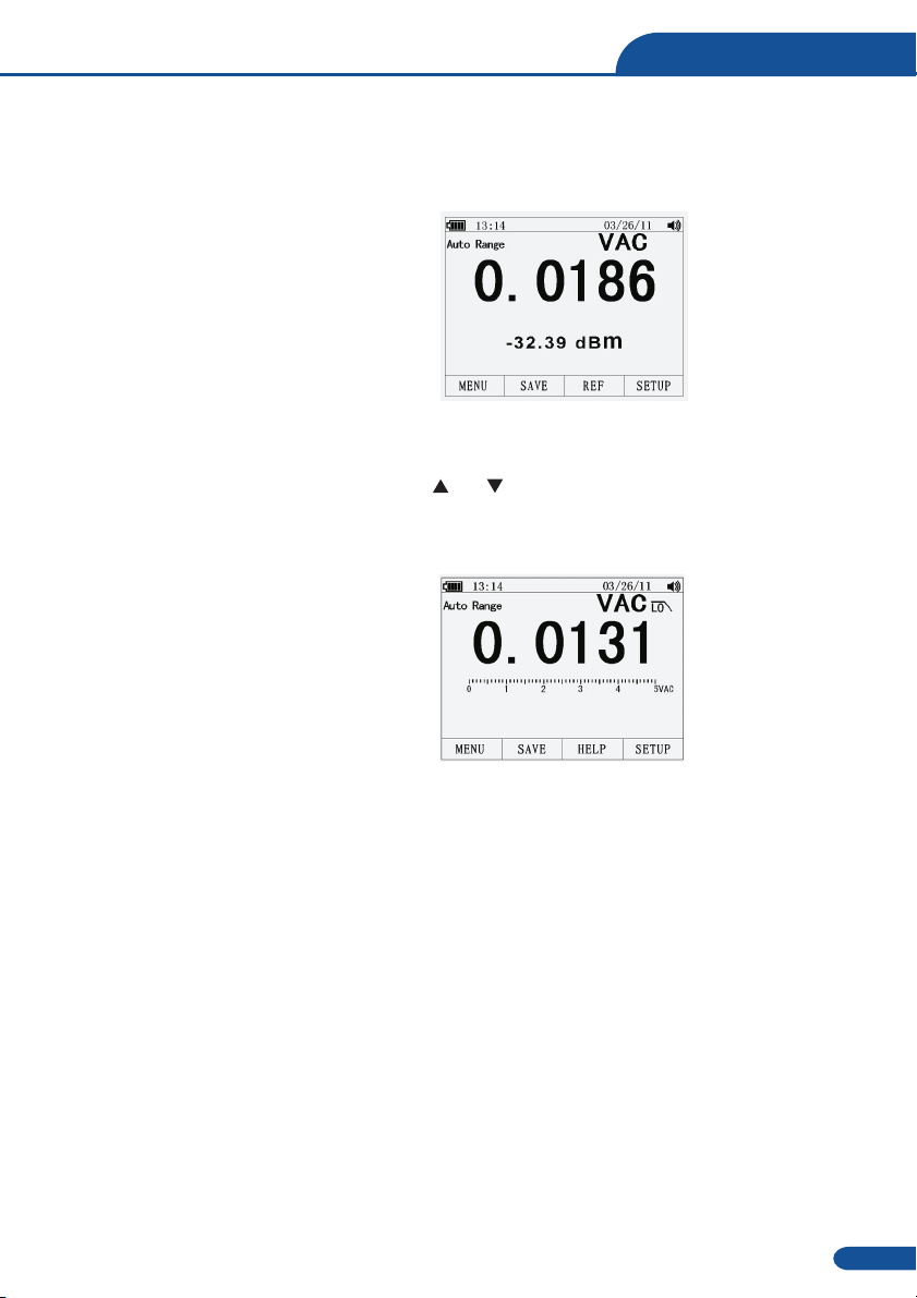
5-3.Making dB Measurements
The Meter is capable of displaying voltage as a dB value, either relative to 1 milliwatt (dBm),
a reference voltage of 1 volt (dBV) or a user-selectable reference value.
1.Set the function switch to the green VAC
position.
2.press the softkey labeled Menu. Move the
menu selector to the menu item labeled
dBm. Press the softkey dBm
3.Insert the black test lead banana plug into
the negative COM jack. Insert red test lead
banana plug into the positive V jack.
4.Read the voltage in the main display and the dBm in the Secondary display
5.To select another reference value, press the softkey labeled Ref to display a message box
with the current reference value. Pressing or , scrolls through the nine predefined
references: 4,8,16,25,32,50,75,600 and 1000. Set the reference by pressing the softkey labeled
OK.
The Meter is equipped with an ac low pass
filter. When measuring ac voltage, press the
soft key labeled Menu to open the function
menu, and move the menu selector to the LO
item. Next, press the softkey labeled LO to
toggle the low pass filter mode .
5-4.Low Pass Filter
13
True RMS Multimeter

5-5.mV Voltage Measurements
Do not measure mV voltages if a motor on the circuit is being switched ON or
OFF. Large voltage surges may occur that can damage the meter.
CAUTION:
1.Set the function switch to the green mV
position.
2.Press the soft key labeled Menu.
Move the menu selector to the menu item
labeled mVDC(mVAC). Press the soft key
mVDC(mVAC).
3.Insert the black test lead banana plug into
the negative COM jack. Insert the red test
lead banana plug into the positive V jack.
4.Read the mV voltage in the display
CAP
Hz%
Temp
10A
mA
μA
Ω
mV
V
OSC
Hz
%
HELP
HOLD
MODE
AUTO
REC
HOLD
RANGE
MAX
MIN ESC
F1 F2 F3 F4
auto range
0 100 200 300 400 500
mVAC
mVAC
500.00
8:10pm
06/13/07
VCAPΩ
Hz
%
Temp
CAT III 600V
Bluetooth
14
True RMS Multimeter

5-6 Temperature Measurements.
1.Set the function switch to the green
TEMP( C or F) position.
.Insert the Temperature Probe into the input
jacks, making sure to observe the correct
polarity.
.Read the temperature in the display
.To input a temperature offset value, press
the softkey labeled Offset to open a message
box with the present offset value.
Use and to position the cursor over
one of the digits or the polarity sign.
Use and to scroll through the numbers
for each digit in the offset or switch between
a + or – offset. With the desired value
displayed, press the softkey labeled OK to
set the temperature offset.
°°
2.press the soft key labeled Menu. Move the
menu selector to the menu item labeled
TEMP. Press the soft key TEMP(C or F).
3
4
5
5-7.Frequency Measurements
1.Set the function switch to the green Hz%
position.
2.Insert the black test lead banana plug into
the negative COM jack. Insert the red test
lead banana plug into the positive V jack.
3.Read the Frequency in the display
CAP
Hz
%
Temp
10A
mA
μA
Ω
mV
V
OSC
Hz
%
HELP
HOLD
MODE
AUTO
REC
HOLD RANGE
MAX
MIN ESC
F1 F2 F3 F4
auto range
°C
100.00
8:10pm
06/13/07
VCAPΩ
Hz
%
Temp
CAT III 600V
Bluetooth
CAP
Hz
%
Temp
10A
mA
μA Ω
mV
V
OSC
Hz%
HELP
HOLD
MODE
AUTO
REC
HOLD
RANGE
MAX
MIN ESC
F1 F2 F3 F4
auto range
Hz
50.000
8:10pm
06/13/07
0.00%
VCAPΩ
Hz
%
Temp
CAT III 600V
Bluetooth
15
True RMS Multimeter
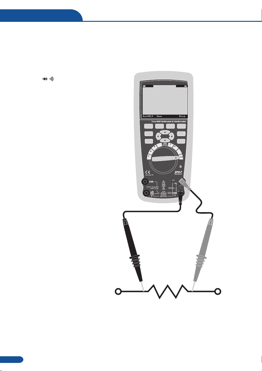
5-8.Resistance Measurements
WARNING: To avoid electric shock, disconnect power to the unit under test and discharge
all capacitors before taking any resistance measurements.
Remove the batteries and unplug the line cords.
1.Set the function switch to the green
J
Ω CAP position.
2.Insert the black test lead banana plug into
the negative COM jack. Insert the red test
lead banana plug into the positive Ω ack.
3.Read the resistance in the display.
CAP
Hz
%
Temp
10A
mA
μA
Ω
mV
V
OSC
Hz
%
HELP
HOLD
MODE
AUTO
REC
HOLD
RANGE
MAX
MIN ESC
F1 F2 F3 F4
auto range
50.000
8:10pm
06/13/07
MΩ
VCAPΩ
Hz
%
Temp
CAT III 600V
Bluetooth
16
True RMS Multimeter

5-9.Continuity Check
To avoid electric shock, disconnect power to the unit under test and discharge all
capacitors before taking any resistance measurements. Remove the batteries and unplug
the line cords.
WARNING:
1.Set the function switch to the green
Ω CAP position.
2.Press the soft key labeled Menu. Move the
menu selector to the menu item labeled
Beeper. Press the soft key Beeper.
3.Insert the black test lead banana plug into
the negative COM jack. Insert the red test
lead banana plug into the positive jack.
4.If the resistance is less than approximately
25Ω, the audible signal will sound. If the
circuit is open, the display will indicate “OL”.
CAP
Hz
%
Temp
10A
mA
μA
Ω
mV
V
OSC
Hz
%
HELP
HOLD
MODE
AUTO
REC
HOLD
RANGE
MAX
MIN ESC
F1 F2 F3 F4
auto range
25.000
8:10pm
06/13/07
Ω
VCAPΩ
Hz
%
Temp
CAT III 600V
Bluetooth
17
True RMS Multimeter

5-10.Diode Test
1.Set the function switch to the green
Ω CAP position.
2.Press the soft key labeled Menu. Move the
menu selector to the menu item labeled
Diode. Press the soft key Diode.
3.Insert the black test lead banana plug into
the negative COM jack and the red test
lead banana plug into the positive V jack.
5.Forward voltage will typically indicate
0.400 to 3.200V. Reverse voltage will
indicate “OL”. Shorted devices will indicate
near 0V and an open device will indicate
“OL” in both polarities.
CAP
Hz
%
Temp
10A
mA
μA
Ω
mV
V
OSC
Hz
%
HELP
HOLD
MODE
AUTO
REC
HOLD
RANGE
MAX
MIN ESC
F1 F2 F3 F4
auto range
V
0.400
8:10pm
06/13/07
VCAPΩ
Hz
%
Temp
CAT III 600V
Bluetooth
18
True RMS Multimeter

5-11.Capacitance Measurements
WARNING: To avoid electric shock, disconnect power to the unit under test and discharge all
capacitors before taking any capacitance measurements. Remove the batteries and unplug
the line cords.
1.Set the rotary function switch to the green
Ω CAP position.
2.Press the soft key labeled Menu. Move the
menu selector to the menu item labeled
Cap. Press the soft key Cap.
3.Insert the black test lead banana plug into
the negative COM jack. Insert the red test
lead banana plug into the positive V jack.
4.Read the capacitance value in the Display
CAP
Hz
%
Temp
10A
mA
μA
Ω
mV
V
OSC
Hz
%
HELP
HOLD
MODE
AUTO
REC
HOLD RANGE
MAX
MIN ESC
F1 F2 F3 F4
auto range
mF
10.00
8:10pm
06/13/07
VCAPΩ
Hz
%
Temp
CAT III 600V
Bluetooth
19
True RMS Multimeter

5-12.DC Current Measurements
CAUTION: Do not make 20A current measurements for longer than 30 seconds. Exceeding
30 seconds may cause damage to the meter and/or the test leads.
1.Insert the black test lead banana plug into
the negative COM jack.
2.For current measurements up to 5000 A DC,
set the function switch to the yellow A
position and insert the red test lead banana
plug into the A/mA jack.
3.For current measurements up to500mA DC,
set the function switch to the yellow mA
position and insert the red test lead banana
plug into the A/mA jack.
4.For current measurements up to 10A DC,
set the function switch to the yellow 10A
position and insert the red test lead banana
plug into the 10A jack.
5.Press the MODE button to indicate “DC”
on the display.
6.Read the current in the display.
µ
µ
µ
µ
CAP
Hz
%
Temp
10A
mA
μA
Ω
mV
V
OSC
Hz
%
HELP
HOLD
MODE
AUTO
REC
HOLD
RANGE
MAX
MIN ESC
F1 F2 F3 F4
auto range
0 100 200 300 400 500
ADC
ADC
10.000
8:10pm
06/13/07
VCAPΩ
Hz
%
Temp
CAT III 600V
Bluetooth
20
True RMS Multimeter

5-13.AC Current Measurements
CAUTION: Do not make 10A current measurements for longer than 30 seconds. Exceeding
30 seconds may cause damage to the meter and/or the test leads.
1.Insert the black test lead banana plug into
the negative COM jack.
2.For current measurements up to 5000 A AC,
set the function switch to the yellow A
position and insert the red test lead banana
plug into the A/mA jack.
3.For current measurements up to 500mA AC,
set the function switch to the yellow mA
position and insert the red test lead banana
plug into the A/mA jack.
4.For current measurements up to 20A AC,
set the function switch to the yellow 10A
position and insert the red test lead banana
plug into the 10A jack.
5.Press the soft key labeled Menu. Move the
menu selector to the menu item labeled AC.
Press the soft key AC.
6.Read the current in the display
µ
µ
µ
µ
CAP
Hz
%
Temp
10A
mA
μA
Ω
mV
V
OSC
Hz%
HELP
HOLD
MODE
AUTO
REC
HOLD
RANGE
MAX
MIN ESC
F1 F2 F3 F4
auto range
0 100 200 300 400 500
AAC
AAC
10.000
8:10pm
06/13/07
VCAPΩ
Hz
%
Temp
CAT III 600V
Bluetooth
21
True RMS Multimeter

5-14.Understanding Function Menus
Each primary measurement function (rotary switch position) has a number of optional
sub-functions or modes accessed by pressing the softkey labeled Menu (F1). A typical menu
is shown in Figure.
Menu selection is indicated by the filled-in
black square(hereafter the menu selector)
to the left of a menu item. Use the four
front-panel cursor buttons ( ) to
position the menu selector next to a menu
item. As the menu selector moves between
menu items, the four softkeys and their labels
change to reflect the available functions
and/or modes available for the selection
menu item.
While operating the Meter, more information about a selected function, a front-panel button,
or a menu item may be necessary. Press soft key HELP to open an information window that
lists topics covering the functions and modifiers that are available at the time the button is
pressed. Each topic provides a brief explanation on a Meter function or feature. The number
of information topics displayed at any one time may exceed the display area. Use the softkeys
labeled Next and Prev to move from topic to topic. Use the softkey labeled More or and
to scroll through the information a full screen at a time.
5 15.Using Help
-
22
True RMS Multimeter

5-16.Measuring AC and DC Signals
The Meter is capable of displaying both AC and DC signal components (voltage or current)
as two separate readings or one AC+DC(RMS) value combined. As shown in Figure , the
Meter displays ac and dc combinations two ways: DC displayed over AC (DC,AC), and AC
combined with dc (AC+DC). Select one of these three displays using the Function and Mode
menu. With the rotary switch set to V, mV, A, mA,or uA, press the soft key labeled Menu.
Move the menu selector to the menu item labeled AC+DC. At this point, three different soft key
labels indicate AC+DC (F1),and DC,AC (F2). Press the soft key that presents these two
signals as needed. While in any of the three AC+DC modes, peak measurements, frequency,
duty cycle, relative %, and period measurements are not allowed. In addition to these modes,
MIN MAX, relative.
5-17.Capturing Minimum and Maximum Values
The MAX MIN Record mode captures minimum, average, and maximum input values. When the
input goes below the recorded minimum value or above the recorded maximum value, the
Meter beeps and records the new value. The Meter stores the elapsed time since the recording
session was started at the same time. The MAX MIN mode also calculates an average of all
readings taken since the MAX MIN mode was activated. This mode is for capturing intermittent
readings,recording minimum and maximum readings unattended, or recording readings while
equipment operation precludes watching the Meter. The MIN MAX mode is best for recording
power supply surges, inrush currents, and finding intermittent failures. Response time is the
length of time an input must stayat a new value to be captured as a possible new minimumor
maximum value.
To activate the MAX MIN mode, press MAX MIN. As shown in Figure, the Meter displays e
at the top of the measurement page, and the MAX MIN start date and time along the bottom of the
page. In addition, the recorded maximum, average, and minimum values appear in the secondary
display with their respective elapsed times.
To stop a MIN MAX recording session, press
the softkey labeled Stop. The summary
information in the display freezes, and the
softkeys change function to allow saving
the collected data. Pressing the softkey
labeled Close exits the MIN MAX record
session without saving the collected data.
23
True RMS Multimeter
Table of contents
Other ENDEAVOUR Measuring Instrument manuals


Popular Measuring Instrument manuals by other brands

Endress+Hauser
Endress+Hauser Proline Promag W 400 HART operating instructions

Lumel
Lumel ND10 TYPE user manual

IFM Electronic
IFM Electronic Efector 300 SI0556 operating instructions

Packeteer
Packeteer PacketShaper 6500 manual

pico Technology
pico Technology HumidiProbe quick start guide

OHAUS
OHAUS MB23 instruction manual


