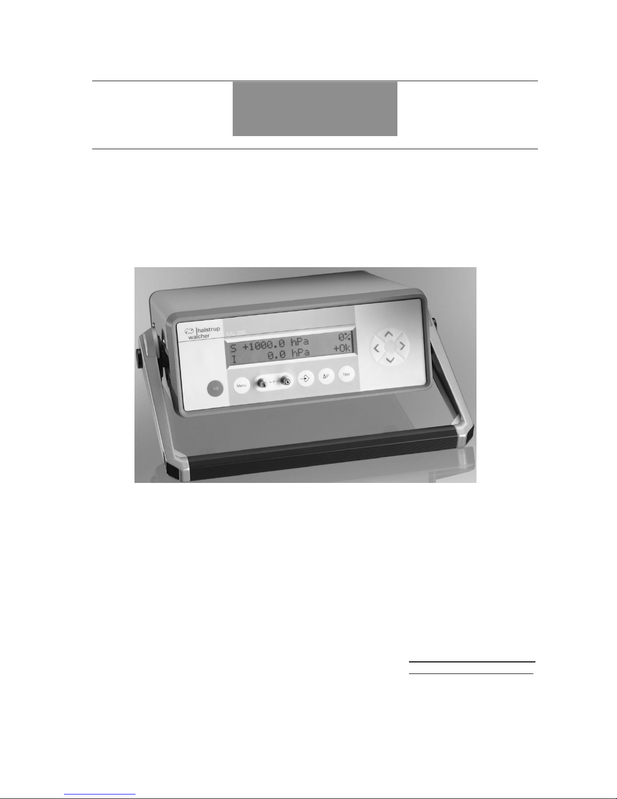
Instruction Manual KAL 100/200
4
3 Safety precautions
3.1 Appropriate use
The KAL 200 calibration device is used for testing and calibrating pressure sensors.
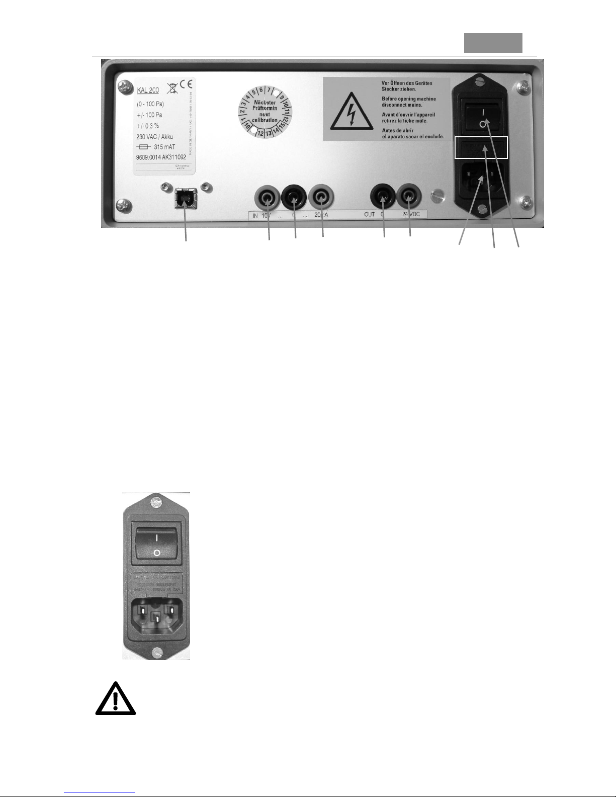
Always observe the operating requirements – particularly the permissible supply voltage –
indicated on the rating plate and in the “Technical data” section of this manual.
The instrument may only be handled as indicated in this manual. Modifications to the instrument
are prohibited. The manufacturer is not liable for damages caused by improper use or failure to
follow these instructions. Violations of this type render all warranty claims null and void.
3.2 Shipping, assembly, electrical connections and start-up
Please do not close the pressure inlets during shipping! Changes in barometric pressure may
damage devices with low measuring ranges.
Assembly and the electrical connections should only be handled by professionals. Only
technical personnel who are appropriately trained and authorized by the operator of the facility
may assemble the instrument and set up its electrical connections.
Pressurized air or breath is not to be used for performance tests, as this could damage
instruments with low measurement ranges.
Measurement errors may occur if the instrument is not kept protected from sunlight.
See the individual sections of this manual for specific safety precautions.
3.3 Troubleshooting, maintenance, repairs, disposal
The individual responsible for the electrical connections must be notified if the instrument is
damaged or if errors occur that cannot be corrected as indicated in Section 10.
This individual must take the instrument out of service until the error has been corrected and
ensure that it cannot be used unintentionally.
Always unplug the power cord before opening the instrument!
This instrument requires no maintenance.
Only the manufacturer may perform repairs that require the housing to be opened.
The electronic components of the instrument contain materials that can be reused. The
instrument must therefore be sent to a recycling plant when you no longer wish to use it. The
environment codes of your particular country must be complied with.
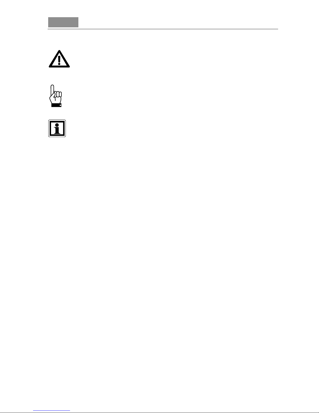
3.4 Symbols
The symbols shown here are used throughout the following text to highlight the hazards
associated with using the KAL 200 and to point out important information for operating the
instrument.