Endo CRL-4000 Series User manual

Supply this manual to the user.
INSTRUCTION MANUAL
CABLE REEL
CRL - 4000 SERIES
CRL - 5000 SERIES
CRL - 6000 SERIES
CRL - 7000 SERIES
・
・・
・Read this manual before use.
・
・
・
・Keep this manual available.
ENDO KOGYO CO., LTD
RM-10547a
Issued on Apr 2013
Copied digital data
from http://www.endo-kogyo.co.jp/

Copyright and liabilities
The copyright for this manual belongs to Endo Kogyo Co., Ltd.
The manual is provided for the limited purpose of supporting the safe and proper use of
the product. It cannot be used for other purposes.
The customer may not use or make copies of this manual, in whole or in part, outside of
this purpose without receiving prior consent from Endo Kogyo Co., Ltd.
The customer is also prohibited from translating or modifying the content of the manual,
in whole or in part.
The content described in the manual is subject to change without advance notice.
Please note this in advance.
November 2019 ENDO KOGYO CO., LTD.
Copied digital data
from http://www.endo-kogyo.co.jp/

SAFETY ALERT SYMBOL AND ALERT SIGNS
Please read this manual carefully and follow its instructions.
The SAFETY ALERT SYMBOL ), WARNING, CAUTION,
and NOTE carry special messages.
This SAFETY ALERT SYMBOL is used to all your attention
to items or operations that ould be dangerous to you or other persons using
this equipment.
Please read these messages and follow these instru tions arefully.
: WARNING indi ates a hazardous situation whi h,
if not avoided, ould result in death or serious injury.
: CAUTION indi ates a hazardous situation whi h,
if not avoided, ould result in minor or moderate injury,
damage or destru tion of the equipment and others.
NOTE:
::
:NOTE indi ates a spe ial instru tion in operation or maintenan e.
Copied digital data
from http://www.endo-kogyo.co.jp/

Contents
1. Safety instru tion ························································ 1
2. Terminolo y definitions ·························································································· 4
3. Product description ································································································ 5
3-1. Models and specifications
3-2. Names of main parts
4. Installation ············································································································8
4-1. Checks before installation
4-2. Installation
4-3. Ground connection work
5. Cable connection ····································································································9
5-1. Calculation of required cable len th on windin side
5-2. Cable connection
6. Sprin tension adjustment ····················································································13
6-1. Relationship between windin torque and drum turns
6-2. Standard value of initial sprin turns and calculation for upper limit of
initial sprin turns.
6-3. Initial tension settin
7. Measures a ainst uneven windin ·········································································14
7-1. Checks before adjustments
7-2. Adjustments
8. Safety instructions on use ·····················································································15
9. Special accessories ·······························································································16
10. Periodic inspections ····························································································17
10-1. Visual inspections
10-2. Slip rin inspections
10-3. Stora e
11. Troubleshootin ··································································································20
12. Brush and slip rin replacement ··········································································20
12-1. Brush replacement
12-2. Brush holder replacement
12-3. Slip rin replacement
13. Sprin replacement ····························································································23
13-1. Disassembly of slip rin assembly and bracket
13-2. Disassembly and reassembly accordin to sprin structure
13-3. Common reassembly method
13-4. Sprin disposal1
14. Parts List ···········································································································38
Copied digital data
from http://www.endo-kogyo.co.jp/
-
1
-
1. Safety instru tions
Re ardin name plates, warnin labels and labels:
・
・・
・Never remove or defa e any name plates, warning labels or labels whi h are atta hed to
the body.
The operator should always observe them.
Re ardin installation (pa e 8):
・
・・
・Never use in ignitable or explosive atmospheres.
・
・・
・Take suffi ient are not to kno k or drop the reel when handling.
Never use the arm of the guide roller (spe ial a essories) to lift the reel.
Re ardin round connection work (pa e 9):
・
・・
・Ele tri sho k hazard.
Do the ground onne tion work.
・
・・
・Never onne t the earth line to the following:
Gas pipes, et . : Danger of ignition or an explosion.
Phone lines / lightning rods : Danger of being stru k by lightning.
Along plasti water pipes : Does not a t as an earth.
Re ardin cable connection (pa e 10):
・
・・
・Ele tri sho k hazard.
Turn off the power before arrying out any work.
・
・・
・Do not install able to drum more than 2-3 times round.
(2-3 times means winding length & initial spring turns)
Make free spa e in drum, otherwise able ould spill out from drum over.
If able spilled, it auses a idents as a able utting.
・
・・
・When used for verti al lift or horizontal stret h appli ation, in order to
prevent severing of the able and then a fall in ase of a spring breakage, prote t the able
by wrapping rubber or the like around the able portion whi h onta ts with the oblong
hole in the drum over.
・
・・
・Che k the wire onne tions are sound and there are no wiring errors.
・
・・
・Never allow the able (leads) onne ted to the slip rings to protrude over 10mm from the
terminal plate upper surfa e for slip ring apa ities of 10A, 20A and 50A, or over 30mm
from the top of the lead bolt for slip ring apa ities of 100A and 150A.
・
・・
・Leave suffi ient room for onne ting the able (leads) to the brushes so as not to apply
ex essive for e to the brushes.
・
・・
・Never obliquely atta h the terminal lugs to the brush holder. If obliquely atta hed, the
insulator length will be insuffi ient, resulting in poor insulation.
・
・・
・Se urely tighten the ross re essed head s rews to atta h the dust proof over and the
onne tor nut to prevent rain penetration.
Take suffi ient are not to damage the seal ring during any work.
Copied digital data
from http://www.endo-kogyo.co.jp/

-
2
-
Re ardin initial tension settin (pa e 14):
・
・・
・Never let go of the drum during any work.
When released, the drum suddenly rotates, possibly ausing personal injury.
・
・・
・After setting the initial tension, wire onne tion requires more than 2 people to se ure
the drum and onne t the able.
Safety instructions on use (pa e 15):
・
・・
・Never approa h the moving parts during operation.
There is a danger of being aught up.
・
・・
・Turn off the power immediately in ase of any trouble to avoid the problem es alating.
・
・・
・Never use the reel when damaged or abnormal sound/vibration o urs.
・
・・
・Never alter the reel or its a essories.
・
・・
・Never let go of or unfasten the able from the fixed points when the able is pulled out.
The able will rewind suddenly, possibly ausing personal injury.
・
・・
・Use within the rated values of the operating voltage and urrent.
Refer to the name plate atta hed to the body.
・
・・
・Never pull out the able past the winding length. Always leave 2 - 3 dead turns
on the drum. (To the sign of red tape)
Put sign (red tape) on the 2 – 3 dead turns when installing or repla ing the able.
Re ardin periodic inspections (pa e 17):
・
・・
・Periodi ally inspe t the reel and repla e any worn or damaged parts.
Carefully he k the able has no damage.
・
・・
・If a malfun tion is found during a periodi inspe tion, never reuse the reel but repair
immediately.
・
・・
・Allow the able to fully wind onto the drum to give the minimum winding tension before
arrying out inspe tions.
・
・・
・Ele tri sho k hazard.
Turn off the power before removing the dust proof over.
・
・・
・Verify safety using some kind of ele tri al test sensor before arrying out inspe tions.
・
・・
・Always put up an instruction sign ("Equipment being inspected", "Do not turn on the power",
etc.) before carrying out periodic inspections or repair.
・
・・
・Ta e care as the slip ring assembly can still be very hot even if the power is cut.
・
・・
・Always use genuine parts for replacement.
・
・・
・Test the insulation after the reel has been stored for a long time.
Copied digital data
from http://www.endo-kogyo.co.jp/
-
3
-
Regarding brush and sli ring re lacement ( age 20):
・
・・
・Electric shoc hazard.
Turn off the power and verify safety using some ind of electrical test sensor before carrying out
replacement.
・
・・
・Allow the cable to fully wind onto the drum to give the minimum winding tension before
carrying out replacement.
・
・・
・Always put up an instruction sign ("Equipment being inspected", "Do not turn on the power",
etc.) before carrying out replacement.
・
・・
・Take are as the slip ring assembly an still be very hot even if the power is ut.
・
・・
・After part repla ement, test the insulation before onne ting the able.
・
・・
・Che k the ondu tion of ea h able ore after able onne tion.
Re ardin sprin replacement (pa e 23):
・
・・
・Ele tri sho k hazard.
Turn off the power and verify safety using some kind of ele tri al test sensor before
arrying out repla ement.
・
・・
・When dis onne ting the mating equipment side wiring on the able winding side, the drum
may suddenly rotate.
Allow the able to fully wind onto the drum to give the minimum winding tension, then
dismantle the mating equipment side wiring with more than 2 people to se ure the drum
and dismantle the wiring.
・
・・
・Allow the dismantled able to wind around the drum, slowly turning the drum until the
winding tension in the drum is released.
Never disassemble until the reel's winding tension is released.
The spring will burst out and ause personal injury.
・
・・
・Never disassemble using any other disassembly pro edure.
If disassembled in orre tly, the spring will burst out and ause personal injury.
・
・・
・Never remove the spring from the spring ase.
If removed, the spring will expand explosively and ause personal injury.
・
・・
・Treat and dispose of the spring a ording to the instru tions.
・
・・
・Always put up an instruction sign ("Equipment being inspected", "Do not turn on the power",
etc.) before carrying out periodic inspections or repair.
Copied digital data
from http://www.endo-kogyo.co.jp/

-
4
-
2. Terminology definitions
The terminolo y used in this manual will be explained here.
If there is any terminolo y which is unclear or not included in this section, please contact
our company.
Windin methods: Fi ure 1
Forward windin : The windin direction when Fi ure 2
viewed from the bracket side is
ri ht (clockwise).
Reverse windin : The windin direction when
viewed from the bracket side is
left (counterclockwise).
Forward seatin : The installation plate (base plate)
is located under the drum.
Reverse seatin : The installation plate (base plate) Fi ure 3
is located on the opposite side of the drum.
C-class round,
connection work: applied to non-char in parts of electric
equipment or cable metal jackets, the round
resistance of which should be 10 ohms or less.
Dead turns : The 2-3 turns of cable wrapped around the drum other than the used
windin len th.
Initial sprin turns : The applied initial tension to the sprin .
The initial tension is required for windin the cable on the drum.
Reverse
seating
Forward
seating
View from
the bracket
side.
Forward
winding
(Clockwise)
Reverse
winding
(Counter
clockwise)
Horizontal drag ,two-way payout
Vertical
lift
Horizontal retrieve
Horizontal stretch
Vertical
retrieve
Vertical
lift
Horizontal retrieve ,two-way payout
Horizontal drag
Horizontal stretch
Vertical
retrieve
Moving reel Fixed reel
Copied digital data
from http://www.endo-kogyo.co.jp/
-
5
-
3. Produ t Des ription
3-1. Models and specifications
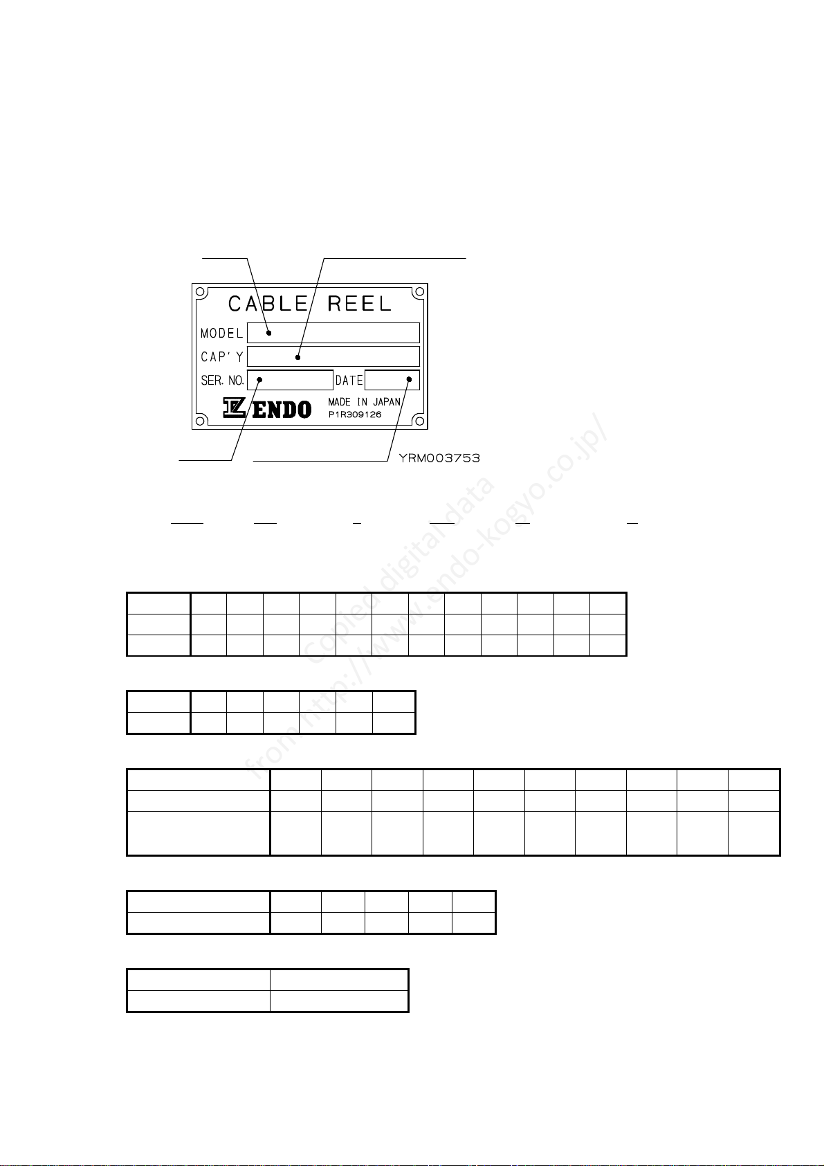
(1) Models
Please observe the name plate attached to the main body.
Refer to Fi ure 5 (pa e 7) for the attached location.
Fi ure 4
MODEL: The product model is shown.
Please check if this manual
matches with the product.
Refer to Table 1.
CAP'Y: The slip rin capacity is shown.
■ Model description
CRL - 6M 7 112 W - R
Series Drum size Drum cover Sprin Sprin Windin
name and width size type combination direction
Drum size and width (mm)
Code 4M
4 4A
5M
5 5A
6M
6 6A
7M
7 7A
Size 280
280
280
360
360
360
440
440
440
550
550
550
Width 127
165
217
127
165
217
172
220
275
172
220
275
Drum cover size (mm)
Code 4 5 6 7 8 9
Size 440
510
630
750
870
1000
Sprin type
Sprin code 24 48 36 72 55 110 56 112 75 150
Number of sprin s
24×1
24×2
36×1
36×2
55×2
55×2
56×1
56×2
75×1
75×2
Total sprin torque
N・m {k f・m}
23.5
{2.4}
47.0
{4.8}
35.3
{3.6}
70.6
{7.2}
53.9
{5.5}
107.8
{11.0}
54.9
{5.6}
109.0
{11.2}
73.5
{7.5}
147.0
{15.0}
Sprin combination
Code None
W T F V
Number of sets 1 2 3 4 5
Windin direction
None R
Forward windin
Reverse windin
Slip ring capacity
Manufactured date
Serial
Model
Copied digital data
from http://www.endo-kogyo.co.jp/

-
6
-
(2) Specifications
Table 1
Model
Maximum
sprin
torque
N・m
{ k f・m }
Calculated
maximum
sprin
tension
N { k f }
Total
number of
sprin
turns
Sprin
structure
Reference
mass
k
CRL-4M424
CRL-4M424-R
23.5
{ 2.4 }
166
{ 17.0 } 13 E 28
CRL-4424W
CRL-4424W-R
23.5
{ 2.4 }
166
{ 17.0 } 26 G 34
CRL-4424T
CRL-4424T-R
23.5
{ 2.4 }
166
{ 17.0 } 39 G 40
CRL-4424F
CRL-4424F-R
23.5
{ 2.4 }
166
{ 17.0 } 52 G 46
CRL-4524T
CRL-4524T-R
23.5
{ 2.4 }
166
{ 17.0 } 39 G 42
CRL-4524F
CRL-4524F-R
23.5
{ 2.4 }
166
{ 17.0 } 52 G 48
CRL-5M636
CRL-5M636-R
35.3
{ 3.6 }
196
{ 20.0 } 13 E 42
CRL-5636W
CRL-5636W-R
35.3
{ 3.6 }
196
{ 20.0 } 26 G 52
CRL-5636T
CRL-5636T-R
35.3
{ 3.6 }
196
{ 20.0 } 39 G 62
CRL-5636F
CRL-5636F-R
35.3
{ 3.6 }
196
{ 20.0 } 52 G 72
CRL-5655W
CRL-5655W-R
53.9
{ 5.5 }
294
{ 30.0 } 24 G 57
CRL-5655T
CRL-5655T-R
53.9
{ 5.5 }
294
{ 20.0 } 36 G 70
CRL-6756F
CRL-6756F-R
54.9
{ 5.6 }
245
{ 25.0 } 48 G 97
CRL-6756V
CRL-6756V-R
54.9
{ 5.6 }
245
{ 25.0 } 60 G 110
CRL-6775W
CRL-6775W-R
73.5
{ 7.5 }
333
{ 34.0 } 24 G 85
CRL-6775T
CRL-6775T-R
73.5
{ 7.5 }
333
{ 34.0 } 36 G 100
CRL-6775F
CRL-6775F-R
73.5
{ 7.5 }
333
{ 34.0 } 48 G 115
CRL-6M7112W
CRL-6M7112W-R
109.0
{ 11.2 }
490
{ 50.0 } 24 G 100
CRL-7875T
CRL-7875T-R
73.9
{ 7.5 }
264
{ 27.0 } 36 G 115
CRL-7875F
CRL-7875F-R
73.9
{ 7.5 }
264
{ 27.0 } 48 G 130
NOTICE : The reference mass shown in the table is for a slip rin capacity of 50A×3P,
and does not include accessories such as the uide rollers, turn table and
ratchet mechanism.
※ The method for sprin replacement is different dependin on the sprin structure.
Refer to chapter 13. (pa e 23) "Sprin replacement".
■ Workin conditions
Application area : eneral outside conditions
Surroundin temperature : - 10℃ to + 50℃
Copied digital data
from http://www.endo-kogyo.co.jp/

-
7
-
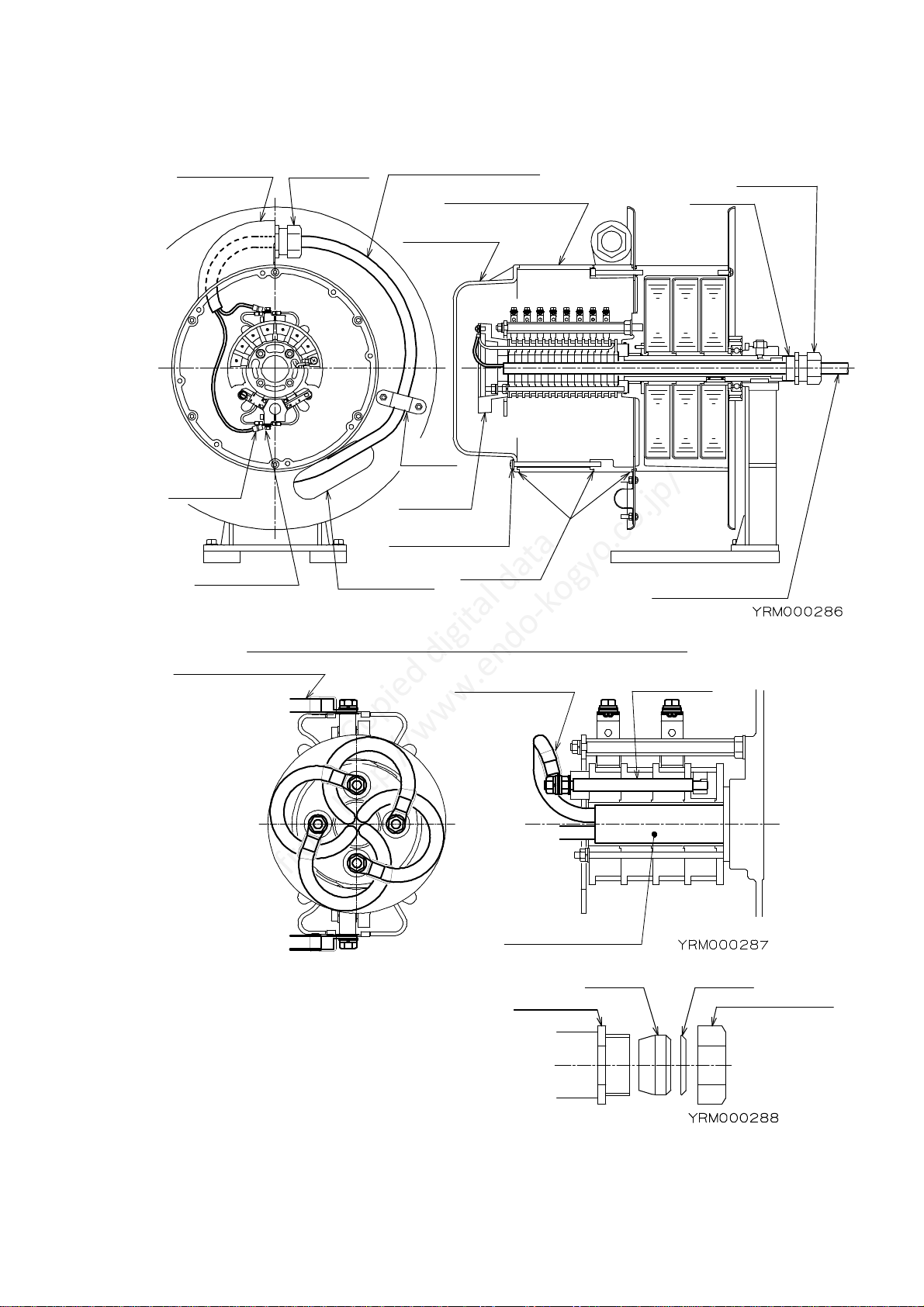
3-2. Name s of main parts
Fi ure 5
Re ardin the accessories, refer to chapter 9. "Accessories" (pa e 16).
(A) Warnin label (B) Warnin label
A warnin is displayed re ardin electric
shock hazards.
A warnin is displayed re ardin sprin
ejection hazards.
(C) Label (D) Label
The required number of initial sprin turns
is displayed.
The windin direction is displayed.
See to
figure 4(page 5).
Being attached
depending on
the slip ring
specifications.
Connector
Dust proof
spacer
Drum
Drum cover
Spring
Spindle
Connector
Bracket
Base plate
Drum cover
Saddle
Cable guide
Slip ring
Dust proof
cover
Copied digital data
from http://www.endo-kogyo.co.jp/

-
8
-
4. Installation
4-1. Checks before installation
・Please check whether the items ordered were received.
(Check the name plate.)
・Check there is no dama e to the product caused durin transportation.
4-2. Installation
Fi ure 6
・
・・
・Never use in ignitable or explosive atmospheres.
・
・
・
・Take suffi ient are not to kno k or drop the reel when
handling.
When lifting the reel, wrap the belt sling around the
drum at least twi e, and lift in stable onditions.
・
・・
・Never use the arm of the guide roller (spe ial a essories) to lift the reel.
・
・・
・For side atta hment or inverse atta hment, use bolts with a strength lassifi ation
above 10.9.
・Place the main body in the fixin location and anchor the bracket securely with 4 bolts.
・The bracket base plate can be chan ed as shown in Fi ure 7
fi ure 7.
NOTE: In order to correctly wind the cable, adjust the
reel position as shown in fi ure 7.
Try to adjust so the center of the drum width
lines up with the cables fixed point on the
matin equipment.
The surface the cable lies on should be
horizontal.
Fi ure 7
Side
attachment
Inverse
attachment
The Y axis should be parallel
with the direction of the
cable pay out and motion
of the equipment.
Line up the center of the
drum width with the cable’s
fixed point on the
mating equipment.
The X axis should
be horizontal.
Moving direction
The surface the cable lies on
should be horizontal.
X axis
Y axis
Cable
Surface
Surface
ixed point
Cable
Forward
seating
Base plate
Hexagon
head bolt
Reverse
seating
Copied digital data
from http://www.endo-kogyo.co.jp/
-
9
-
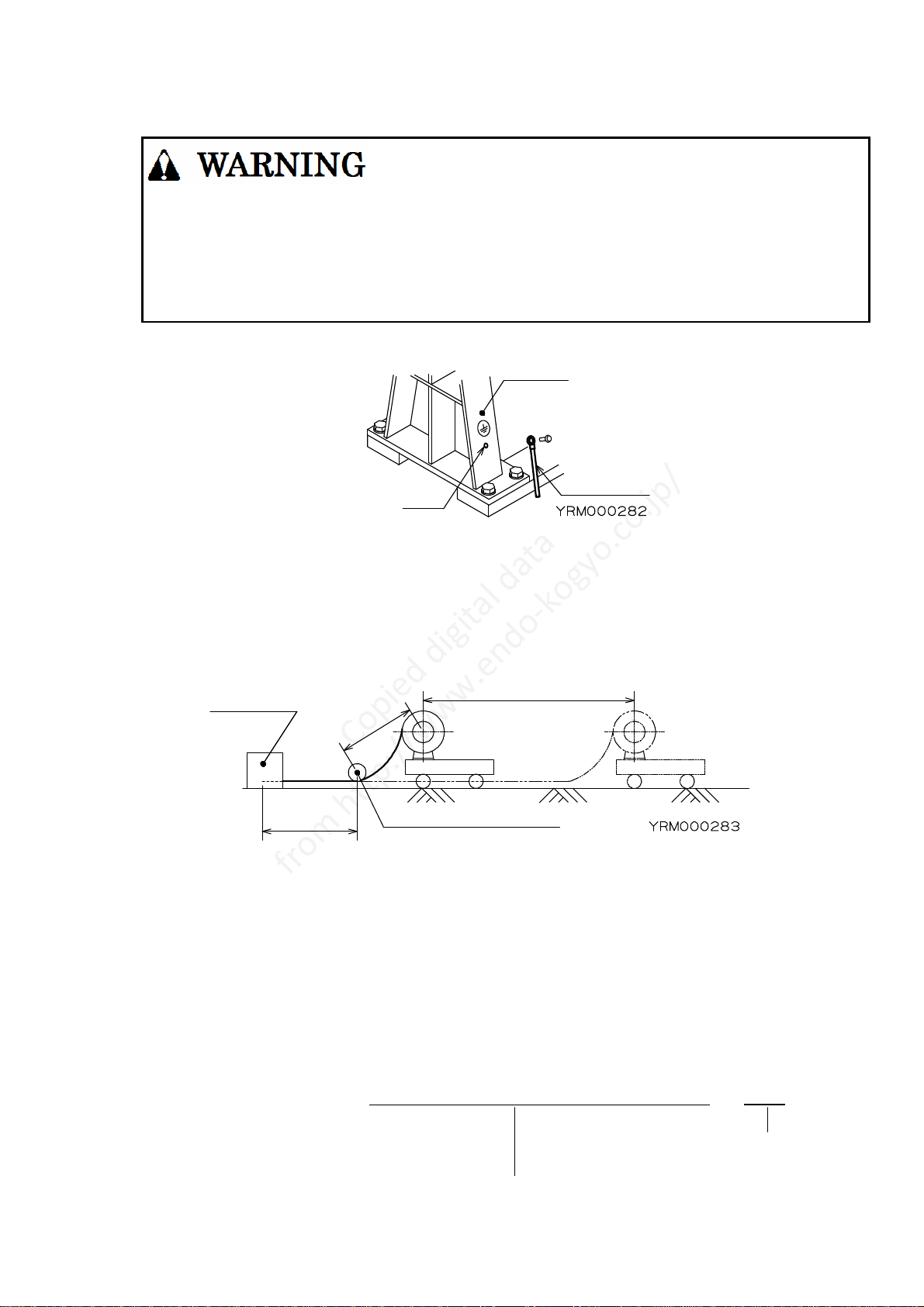
4-3. Ground connection work
・
・・
・Ele tri sho k hazard.
Do the ground onne tion work.
・
・・
・Never onne t the earth line to the following:
Gas pipes, et . : Danger of ignition or an explosion.
Phone lines / lightning rods : Danger of being stru k by lightning.
Along plasti water pipes : Does not a t as an earth.
For earth connection, connect the earth line to the hole installed in the bracket.
Fi ure 9
5. Cable onne tion
5-1. Calculation of required cable len th on windin side
Fi ure 10
Cable len th on windin side = Windin len th + Extension len th + Connection len th
+ Dead turns len th + Connection len th inside reel.
Windin len th = The len th wound onto the drum.
Extension len th = The len th from the cable's fixed point to the end of the windin ,
which is not wound onto the drum.
Connection len th = The len th required to connect the matin equipment to the
cables fixed point.
Dead turns len th = The len th of the 2-3 dead turns.
Connection len th inside reel = Approx 1m.
Required dead turns len th = (Drum diameter + Cable diameter) × π × 2 –
3
Numbers of dead turns
The len ths of 1 drum turn
Bracket
Earth line
Hole
M8
Connection
length
Winding length
E
x
t
e
n
s
i
o
n
l
e
n
g
t
h
Mating
equipment
Cable’s fixed point
Copied digital data
from http://www.endo-kogyo.co.jp/

-
10
-
5-2. Cable connection
・
・・
・Ele tri sho k hazard.
Turn off the power before arrying out any work.
・
・・
・Do not install able to drum more than 2-3 times round.
(2-3 times means winding length & initial spring turns)
Make free spa e in drum, otherwise able ould spill out
from drum over.
If able spilled, it auses a idents as a able utting.
・
・・
・When used for verti al lift or horizontal stret h appli ation,
in order to prevent severing of the able and then a fall
in ase of a spring breakage, prote t the able by wrapping
rubber or the like around the able portion whi h onta ts with the oblong hole (F) in
the drum over (See figure 11).
・
・・
・Che k the wire onne tions are sound and there are no wiring errors.
・
・・
・Never allow the able (leads) onne ted to the slip rings to protrude over 10mm from the
terminal plate upper surfa e for slip ring apa ities of 10A, 20A and 50A, or over 30mm
from the top of the lead bolt for slip ring apa ities of 100A and 150A
(see figures 12 and 13).
If protruding out too far, the fixed side able and the dust proof over will onta t,
damaging the able insulation due to the drum rotation, ausing a spark.
Fi ure 12 Fi ure 13
・
・・
・Leave suffi ient room for onne ting the able (leads) to the brushes so as not to apply
ex essive for e to the brushes.
・
・・
・Never obliquely atta h the terminal lugs to the brush holder.
If obliquely atta hed, the insulator length will be insuffi ient, resulting in poor
insulation.
・
・・
・Se urely tighten the ross re essed head s rews to atta h the dust proof over and the
onne tor nut to prevent rain penetration.
Take suffi ient are not to damage the seal ring during any work.
10mmWithin
Dust proof cover
Fixed side cable
Terminal plate
10A,20A,50A
Lead bolt
Dust proof cover
Fixed side cable
30mmWithin
100A,150A
Figure 11
Copied digital data
from http://www.endo-kogyo.co.jp/
-
11
-
Fi ure 14
Fi ure 15
■ Windin side cable (See fi ure 14,15) Fi ure 16
(1) Loosen the cross recessed head screws
and remove the dust proof cover and
dust proof spacer.
NOTE: The dust proof cover and dust proof
spacer will fall when the cross recessed
head screws are loosened.
Take care not to drop them into the slip rin assembly.
(2) Remove the saddle and the connector nut on the cable uide side.
(3) Pass the cable throu h the oblon hole in the drum cover from the drum side.
Attach the removed nut, washer and sleeve to the cable (See fi ure 16).
Connector nut
Connector
Sleeve Washer
Cross recessed
head screw
Terminal
plate
Saddle
Spindle
Oblong hole
Brush holder Seal ring
Winding side cable
Dust
proof cover
Dust proof spacer
Cable guide
Fixed side cable
Terminal
lug
Connector
Connector
100A,150A connection diagram
Winding side cable
Insulation cap Lead bolt
Fixed side cable
Copied digital data
from http://www.endo-kogyo.co.jp/
-
12
-
(4) Peel the required len th of jacket from the cable, and pass the cable throu h the
cable uide.
Decide on the required len th for peelin to allow sufficient room for connectin the cable
core to the farthest brush holder from the cable uide exit.
(5) Ti hten the connector nut to secure the cable while leavin sufficient room for connectin
each cable core to the brush.
This is important to prevent rain penetration into the slip rin assembly.
NOTE: If the cable cannot be secured by ti htenin the connector nut, make the cable
diameter bi er by wrappin thick tape around the cable, then secure with the
connector nut (See fi ure 17).
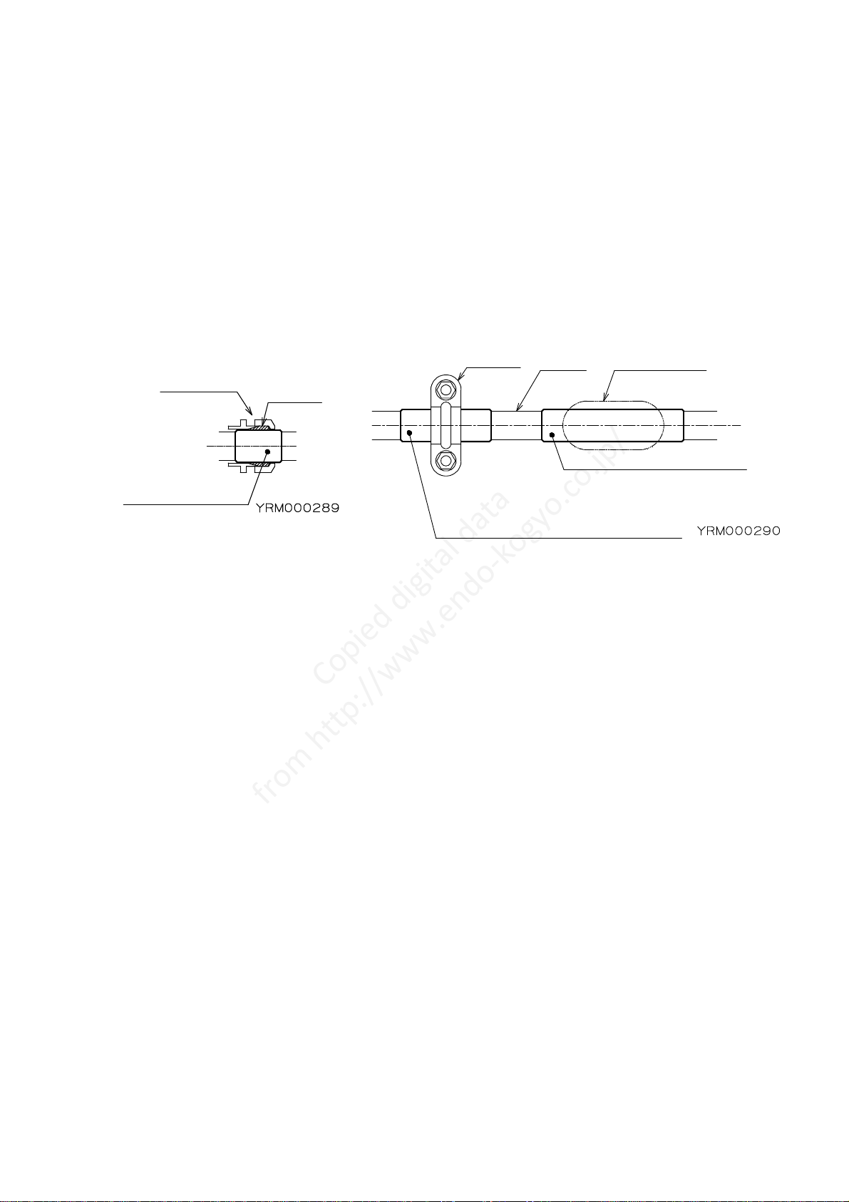
Fi ure 17 Fi ure 18
(6) Wrap thick tape around the cable portion which contacts with the oblon hole in the
drum cover, and fix with the saddle.
If the cable cannot be secured by the saddle, make the cable diameter bi er by wrappin
thick tape around the cable (See fi ure 18).
(7) Attach the terminal lu s to each cable core.
(8) Connect the terminal lu s to the brush holders.
■ Fixed side cable (See fi ure 14, 15 (pa e 11))
(1) Remove the connector nut on the spindle side.
Attach the connector nut, washer and sleeve to the cable.
(2) Peel the jacket from the cable, and pass the cable throu h the spindle.
The peelin len th should be 100mm for slip rin capacities of 10A, 20A and 50A, and
300mm for slip rin capacities of 100A and 150A.
(3) Connect each cable core to the terminal plate or the lead bolts.
NOTE: Check the conduction of each cable core to ensure there are no wirin errors.
(4) Ti hten the connector nut to secure the cable.
This is important to prevent rain penetration into the slip rin assembly.
NOTE: If the cable cannot be secured by ti htenin the connector nut, make the cable
diameter bi er by wrappin thick tape around the cable, then secure with the
connector nut (See fi ure 17).
(5) Attach the dust proof spacer and dust proof cover.
Connector Sleeve
Make the cable
diameter bigger.
For vertical lift or horizontal stretch
application, protect the cable by wrapping
rubber or the like around the cable.
Make the cable diameter bigger.
Wrap at least two turns.
Oblong holeCable
Saddle
Copied digital data
from http://www.endo-kogyo.co.jp/
-
13
-
6. Spring tension adjustment
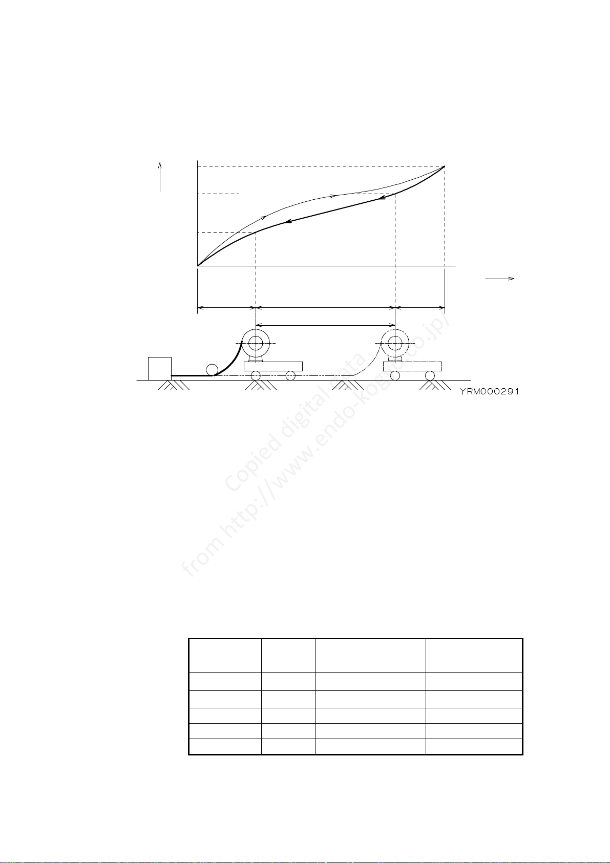
6-1. Relationship between windin torque and drum turns
Fi ure 19
"Number of initial sprin turns" means the number of sprin turns which provides the
initial tension required for windin the cable onto the drum.
"Number of spare sprin turns" means the number of remainin sprin turns when the
cable is fully paid out.
A shorta e of spare sprin turns shortens the sprin life and causes sprin breaka e.
6-2. Standard value of initial sprin turns and calculation for upper limit of
initial sprin turns
(1) Check the total number of sprin turns usin table 1(pa e 6).
(2) Rotate the drum by hand until the cable of the windin len th is fully retracted, checkin
the number of drum turns.
(3) Check the standard value of initial sprin turns and the number of spare sprin turns
usin table 2.
Sprin
combination
Number
of sets
Standard value of
Initial sprin turns
Number of spare
Sprin turns
None 1 1 to 3 1.5 or more
W 2 2 to 6 3 or more
T 3 3 to 9 4.5 or more
F 4 4 to 12 6 or mor
Table 2
V 5 5 to 15 7.5 or mor
Upper limit of initial sprin turns = Total number of sprin turns - (Number of drum turns
+ Number of spare sprin turns)
Winding
torque
MAX
Winding length
Number of
drum turns Spring turns
(Drum turns)
MAX
P
a
y
i
n
go
u
tt
h
ec
a
b
l
e
(
W
i
n
d
i
n
gt
h
es
p
r
i
n
g
)
R
e
c
o
v
e
r
i
n
gt
h
ec
a
b
l
e
(
R
e
l
e
a
s
i
n
gt
h
es
p
r
i
n
g
)
Number
of initial
spring
turns
Number
of spare
spring
turns
Copied digital data
from http://www.endo-kogyo.co.jp/

-
14
-
Example) Model CRL-6M7112W, for the case of 12 drum turns
Accordin to table 1, total number of sprin turns = 24.
Accordin to table 2, standard value of initial sprin turns = 2 - 6,
Number of spare sprin turns = 3 or more.
Upper limit of initial sprin turns = 24 - (12 + 3) = 9.
Then the allowable number of initial sprin turns = 2 - 9.
6-3. Initial tension settin
・
・・
・Never let go of the drum during any work.
When released, the drum suddenly rotates, possibly ausing personal injury.
・
・・
・After setting the initial tension, wire onne tion requires more
than 2 people to se ure the
drum and onne t the able.
(1) Before wire connection, wind the whole cable around the drum.
NOTE: Take care not to twist the cable durin windin .
(2) With the cable still wrapped around the drum, rotate the drum by hand in the payout
direction the same number of turns as the standard value of initial sprin turns.
This becomes "initial sprin turns".
(3) Without lettin the drum rotate, unwind the cable to the extension len th plus the
connection len th and connect the cable to the matin equipment.
Check there are no twists in the cable before connection.
(4) Pull out the cable to the windin len th, then let the cable wind around the drum.
Ensure the drum can recover the cable's full windin len th.
(5) If the drum stops durin recovery, the initial sprin tension is insufficient.
Disconnect the cable from the matin equipment and increase the number of initial
sprin turns in the same manner.
NOTE: Set the initial tension as small as possible and never exceed the upper limit of the
initial sprin turns.
Over-tensionin could cause a sprin breaka e.
7. Measures against uneven winding
"Uneven windin " means the cable is wound on mainly one side of the drum width.
The uneven windin will cause the cable to drop from the drum or recovery problems,
resultin in dama e to the cable.
7-1. Checks before adjustments
(1) Check the reel position is correct.
Refer to chapter 4, section 4-2. "Installation".
Adjust the X and Y axes of the reel.
(2) Check there are no twists in the windin side cable.
Disconnect the cable from the matin equipment and remove any twists.
※ If uneven windin still exists after the above checks, adjust accordin to the next section.
Copied digital data
from http://www.endo-kogyo.co.jp/

-
15
-
7-2. Adjustments
(1) Initial tension modification
Increase the number of initial sprin turns one by one without exceedin the upper limit.
If there is no improvement, set the initial tension back to the first value.
(2) X axis modification
Tilt the X axis at a small an le by insertin a spacer under the bracket.
Fi ure 20
(3) Y axis modification
Tilt the Y axis at a small an le after adjustin the X axis.
Fi ure 21
8. Safety instructions on use
・
・・
・Never approa h the moving parts during operation.
There is a danger of being aught up.
・
・・
・Turn off the power immediately in ase of any trouble to avoid the problem es alating.
・
・・
・Never use the reel when damaged or abnormal sound/vibration o urs.
・
・・
・Never alter the reel or its a essories.
・
・・
・Never let go of or unfasten the able from the fixed points when the able is pulled out.
The able will rewind suddenly, possibly ausing personal injury.
・
・・
・Use within the rated values of the operating voltage and urrent.
Refer to the name plate atta hed to the body.
・
・・
・Never pull out the able past the winding length.
Always leave 2 - 3 dead turns on the drum. (To the sign of red tape)
Put sign (red tape) on the 2 – 3 dead turns when installing or repla ing the able.
Spacer
Spacer
Copied digital data
from http://www.endo-kogyo.co.jp/

-
16
-
9. Spe ial a essories
Fi ure 22
(J) Warnin label
A warnin not to use the uide roller to
lift the reel is displayed.
Never employ a swivel base or a standard turn table for side atta hment or inverse
atta hment.
(1) Turn table Fi ure 23
This can swivel the reel up to 300゜.
When turned, take care the fixed side cable is not put
under excessive force or contacts the reel or surroundin
objects.
An arm type uide roller or pipe type uide roller is required
to ether with the turn table.
Please contact our company in case of side attachment or
inverse attachment, the specifications differ from the standard ones.
(2) Swivel base
This will freely swivel the reel.
An arm type uide roller or pipe type uide roller is required to ether with the
swivel base.
The swivel base is not available for side attachment or inverse attachment.
For installation and so forth, refer to the swivel base instruction manual.
Pipe type guide roller
Stopper
Arm type guide roller
Stopper
Ratchet device
Turn table Swivel base
Ratchet device
Up to 300
Copied digital data
from http://www.endo-kogyo.co.jp/
This manual suits for next models
43
Table of contents
Other Endo Tools manuals


Popular Tools manuals by other brands


Constructor
Constructor CTCID144LI2-3IN1-BM Original instructions

Nederman
Nederman 865 series Original user manual

FAR
FAR RAC 230 Operating instructions and spare parts list

Clarke
Clarke IT1500 Operation & maintenance instructions

pela tools
pela tools 494220 instructions

ACCU-SYSTEMS
ACCU-SYSTEMS DD manual


