Endo HR-2000 Series User manual

Supply this manual to the user.
INSTRUCTION MANUAL
HOSE REEL
HR-2000 SERIES
HR-3000 SERIES
・Read this manual before use.
・Keep this manual available.
ENDO KOGYO CO., LTD
RM-10661a
Issued on Mar. 2020
Copied digital data
from http://www.endo-kogyo.co.jp/

Copyright and liabilities
The copyright for this manual belongs to Endo Kogyo Co., Ltd.
The manual is provided for the limited purpose of supporting the safe and proper use of
the product. It cannot be used for other purposes.
The customer may not use or make copies of this manual, in whole or in part, outside of
this purpose without receiving prior consent from Endo Kogyo Co., Ltd.
The customer is also prohibited from translating or modifying the content of the manual,
in whole or in part.
The content described in the manual is subject to change without advance notice.
Please note this in advance.
November 2019 ENDO KOGYO CO., LTD.
Copied digital data
from http://www.endo-kogyo.co.jp/
SAFETY ALERT SYMBOL AND ALERT SIGNS
Please read this manual carefully and follow its instructions.
The SAFETY ALERT SYMBOL ( ), WARNING, CAUTION,
and NOTE carry special messages.
This SAFETY ALERT SYMBOL is used to call your attention
to items or operations that could be dangerous to you or other persons using
this equipment.
Please read these messages and follow these instructions carefully.
: WARNING indicates a hazardous situation which,
if not avoided, could result in death or serious injury.
:CAUTION indicates a hazardous situation which,
if not avoided, could result in minor or moderate
injury,
damage or destruction of the equipment and others.
NOTE:NOTE indicates a special instruction in operation or maintenance.
Copied digital data
from http://www.endo-kogyo.co.jp/

Scope of warranty and liabilities for the equipment
1. We will repair or replace the product free of charge if a failure due to manufacturing defects
occurs under proper usage during the warranty period.
For details, contact us or your dealer.
2. The warranty will be void in the following cases:
1) Change in ownership.
2) Repair, adjustment, or modification performed by a party other than the manufacturer, agents,
or dealers.
3. The warranty period is one (1) year from the date of purchase except for consumables.
4. Repairs applicable to any of the following shall be charged even during the warranty period:
1) Failure/damage caused by incorrect use.
2) Failure/damage caused by use of non-genuine parts.
3) Failure/damage caused by fire, earthquake, natural disaster, or other unexpected incident.
4) Incident caused by fall, shock, negligence, or by inadequate storage.
5) Failure/damage caused by use of parts or other equipment that are not included in this product.
6) Replacement of consumables.
7) Usage in violation of dangers or cautions stipulated in this Instruction Manual or the warning
labels.
8) Failure/damage caused by any reason that is not attributable to the manufacturer.
5. Warranty exclusions such as mechanical loss.
Either during or after the warranty period, mechanical loss, damage to anything other than our
product(s), or other duties incurred on you/your customer as a result of the failure of our product(s)
are outside the scope of the warranty.
Copied digital data
from http://www.endo-kogyo.co.jp/

Contents
1. Safety instruction··························································1
2. Terminology definitions ····················································································4
3. Product description ·························································································5
3-1. Models and specifications
3-2. Names of main parts
4. Installation ·································································································8
4-1. Checks before installation
4-2. Installation
5. Hose connection ···························································································9
5-1. Calculation of required hose length on winding side
5-2. Hose connection
6. Spring tension adjustment ··············································································· 11
6-1. Relationship between winding torque and drum turns
6-2. Standard value of initial spring turns and calculation for upper limit of initial spring turns
6-3. Initial tension setting
7. Measures against uneven winding ······································································ 13
7-1. Checks before adjustments
7-2. Adjustments
8. Safety instructions on use ··············································································· 14
9. Special accessories ······················································································ 14
10. Periodic inspections ···················································································· 16
10-1. Visual inspections
10-2. Leakage inspection
10-3. Storage
11. Troubleshooting ························································································ 17
12. O-ring replacement ····················································································· 17
13. Spring replacement ····················································································· 19
13-1. Disassembly of bracket
13-2. Disassembly and reassembly according to spring structure
13-3. Common reassembly method
13-4. Spring disposal1
14. Parts list ································································································· 28
Copied digital data
from http://www.endo-kogyo.co.jp/

- 1 -
1. Safety instructions
Regarding name plates, warning labels and labels:
・Never remove or deface any name plates, warning labels or labels which are
attached to the body.
The operator should always observe them.
Regarding installation (page 8):
・Take sufficient care not to knock or drop the reel when handling.
Never use the arm of the guide roller (special accessories) to lift the reel.
Regarding hose connection (page 9):
・Fluid leakage hazard.
Stop supplying the fluid to the hose reel before the work.
・Do not install hose to drum over winding length plus dead turn (2-3 turns).
Make free space in drum, otherwise hose could spill out from drum cover.
If hose spilled, it causes accidents as a hose cutting.
・Connect hose securely to prevent the fluid leakage from connected part.
Regarding initial tension setting (page 12):
・Never let go of the drum during any work.
When released, the drum suddenly rotates, possibly causing personal injury.
・After setting the initial tension, hose connection requires more than 2 people to
secure the drum and connect the hose.
Copied digital data
from http://www.endo-kogyo.co.jp/
- 2 -
Safety instructions on use (page 14):
・Never approach the moving parts during operation.
There is a danger of being caught up.
・Before supplying defferent fluid into the hose, take maker’s advise.
If there is no specification request on the type of fluid application, the product
will be for air, water (less than 80℃), lubricating oil (mineral type),
grease (lithium type).
If you are applying different kinds of fluid from standard fluid type, teke
maker’s advise.
・Shut off the fluid supply immediately in case of any trouble to avoid the problem
escalating.
・Never use the reel when damaged or abnormal sound/vibration occurs.
・Never alter the reel or its accessories.
・Never let go of or unfasten the hose from the fixed points when the hose is pulled
out.
The hose will rewind suddenly, possibly causing personal injury.
・Use within the rated values of maximum working pressure (1.5 MPa {15kgf/cm
2
}).
・Never pull out the hose past the winding length.
Always leave 2 - 3 dead turns on the drum. (To the sign of red tape)
Put sign (red tape) on the 2 - 3 dead turns when installing or replacing the hose.
Regarding periodic inspections (page 16):
・Periodically inspect the reel and replace any worn or damaged parts.
Carefully check the hose has no damage.
・If a malfunction is found during a periodic inspection, never reuse the reel but
repair immediately.
・Allow the hose to fully wind onto the drum to give the minimum winding tension
before carrying out inspections.
・Fluid leakage hazard.
Stop supplying the fluid to the hose reel before carrying out any work.
・Always put up instruction signs ("Equipment being inspected", "Do not open the
valve", etc.) before carrying out periodic inspections or repair.
・Always use genuine parts for replacement.
・Test the fluid leakage on the hose and reel after the reel has been stored for a long
time.
Copied digital data
from http://www.endo-kogyo.co.jp/

- 3 -
Regarding with O-ring replacement (page 17):
・High pressured fluid on hose reel is very dangerous.
Shut off the fluid supply and set 0 pressure in the hose.
・Allow the hose to fully wind onto the drum to give the minimum winding tension
before carrying out replacement.
・Always put up instruction signs ("Equipment being inspected", "Do not open the
valve", etc.) before carrying out O-ring replecement.
・After finishing O-ring replacement, carry out the fluid leakage test on joint and
each connection part.
Regarding spring replacement (page 19):
・High pressured fluid on hose reel is very dangerous.
Shut off the fluid supply, and set 0 pressure in the hose.
・If the winding side hose is disconnected from mating equipment, the drum may
suddenly rotate.
Allow the hose to fully wind onto the drum to give the minimum winding tension,
and work with more than 2 people divided into the person who secure the drum
and the person who disconnect the hose.
Allow the disconnected hose to wind around the drum, and slowly turn the drum
until the winding tension in the drum is released.
・Never disassemble the reel until winding tension is released.
The spring will burst out and cause personal injury.
Even if the spring seems to be broken, never disassemble before ensuring no
winding tension remains by rotating the drum by hand.
・Never disassemble the reel using any other disassembly procedure.
If disassembled incorrectly, the spring will burst out and cause personal injury.
・Never remove the spring from the spring case.
If removed, the spring will expand explosively and cause personal injury.
・Follow the instructions for handling and disposing of the spring.
・Always put up instruction signs ("Equipment being inspected", "Do not open the
valve", etc.) before carrying out spring replecement.
Copied digital data
from http://www.endo-kogyo.co.jp/

- 4 -
2. Terminology Definitions
The terminology used in this manual will be explained here.
If there is any terminology which is unclear or not included in this section, please contact our company.
Winding methods: Figure 1
Forward winding: The winding direction when
viewed from the bracket side is
right (clockwise).
Reverse winding: The winding direction when
viewed from the bracket side is
left (counterclockwise).
Forward seating: The installation plate (base plate) is cated
under the drum.
Reverse seating: The installation plate (base plate) is
located on the opposite side of the drum.
Dead turn: The 2-3 turns of hose wrapped around the drum other
than the used winding length.
Initial spring turn: The applied initial tension to the spring.
The initial tension is required for winding the hose on the drum.
Horizontal drag ,two-way payout
Vertical
lift
Moving reel Fixed reel
Horizontal retrieve
Horizontal stretch
Vertical
retrieve
Vertical
lift
Horizontal retrieve ,two-way payout
Horizontal drag
Horizontal stretch
Vertical
retrieve
View from
the bracket
side.
Forward
winding
(Clockwise)
Reverse
winding
(Counter
clockwise)
Figure 2
Reverse
seating
Forward
seating
Figure 3
Copied digital data
from http://www.endo-kogyo.co.jp/

- 5 -
3. Product Description
3-1. Models and specifications
(1) Models
Please observe the name plate attached to the main body.
Refer to Figure 5 (page 7) for the attached location.
MODEL: The product model is shown.
Please check if this manual matches
with the product.
MAX. WORKING PRESSURE:
Maximum working pressure is
shown.
■Model description
HR - 2A 2 05 W - 1 R
Series Drum size Drum cover Spring Spring Installation Winding
name and width size type combination plate direction
Drum size and width (mm) Drum cover size (mm)
Code 2 2A 3 3A Code 2 3 4 5
Size 200 200 230 230
Size 292 350 440 510
Width 75 110 75 110
Spring type
Spring code 05 10 09 16
Number of springs 05×1 05×2 09×1 16×1
Total spring torque
N・m {kgf・m} 4.9
{0.5} 9.8
{1.0} 8.8
{0.9} 15.6
{1.6}
Spring combination Installation plate
Code None W
None 1
number of sets 1 2 Forward seating Reverse seating
Winding direction
None R
Forward winding Reverse winding
Manufactured date
Serial
Model
Max. working pressure
Figure 4
Copied digital data
from http://www.endo-kogyo.co.jp/

- 6 -
(2) Specifications
Table 1
Model Maximum
spring torque
N・m {kgf・m}
Calculated
maximum
spring tension
N{kgf}
Conection
size
{Rc}
Total number
of spring turns
※
Spring
structure
Reference
Mass
{kg}
HR-2205
HR-2250-R 4.9
{0.5} 49
{5.0} Rc 3/8 20 A 8
HR-2305
HR-2305-R 4.9
{0.5} 49
{5.0} Rc 3/8 20 A 9
HR-2A305W
HR-2A305W-R 4.9
{0.5} 49
{5.0} Rc 3/8 39 C 11
HR-3416
HR-3416-R 15.6
{1.6} 132
{13.5} Rc 1/2 13 A 12
HR-3A409W
HR-3A409W-R 8.8
{0.9} 73
{7.5} Rc 1/2 38 C 16
HR-3A416W
HR-3A416W-R 15.6
{1.6} 132
{13.5} Rc 1/2 26 C 16
HR-3A516W
HR-3A516W-R 15.6
{1.6} 132
{13.5} Rc 1/2 26 C 20
NOTICE: The reference mass shown in the table does not include accessories such as
guide rollers, turn table and ratchet mechanism.
※The method for spring replacement is different depending on the spring structure.
Refer to Chapter 13. "Spring Replacement" (page 19).
■Available fluid
Fluid: Air, Water (less than 80ºC), Lubricating oil (Mineral type), Grease (Lithium type)
Maximum working pressure: 1.5MPa {15kgf/cm2}
■Application
Application area : general outside conditions
Ambient temperature: -10ºC to +50ºC
Copied digital data
from http://www.endo-kogyo.co.jp/
- 7 -
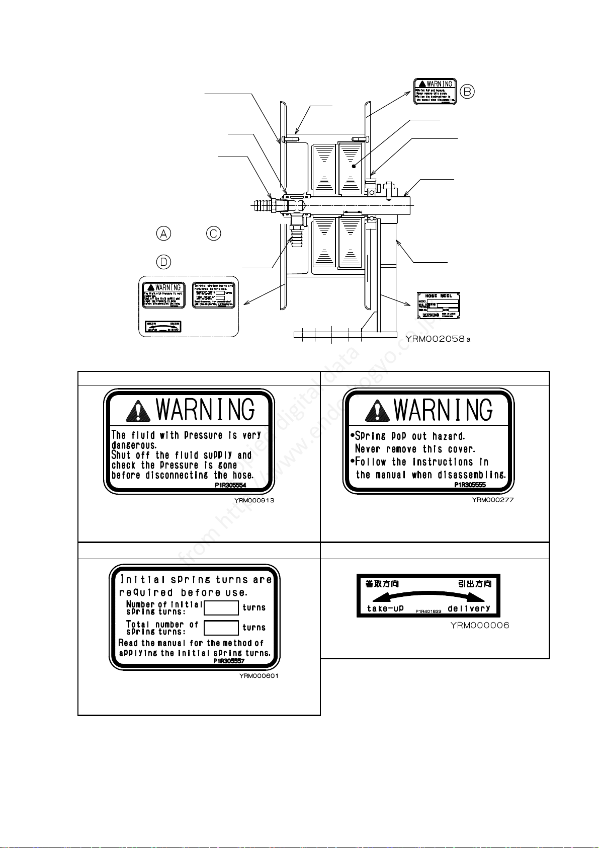
3-2. Names of main parts
Figure 5
Regarding the accessories, refer to Chapter 9. "Accessories" (page 14).
( A ) Warning label ( B ) Warning label
A warning is displayed regarding
fluid pressure hazards.
A warning is displayed regarding
spring ejection hazards.
( C ) Label ( D ) Label
The required number of initial
spring turns is displayed.
The winding direction is displayed.
Bracket
Drum cover
Nipple
Nipple
Drum
Spindle
Drum cover
Joint
Spring
Figure 4(See page 5)
Copied digital data
from http://www.endo-kogyo.co.jp/
- 8 -
4. Installation
4-1. Checks before installation
・Please check whether the items ordered were received.
(Check the name plate.)
・Check there is no damage to the product caused during transportation.
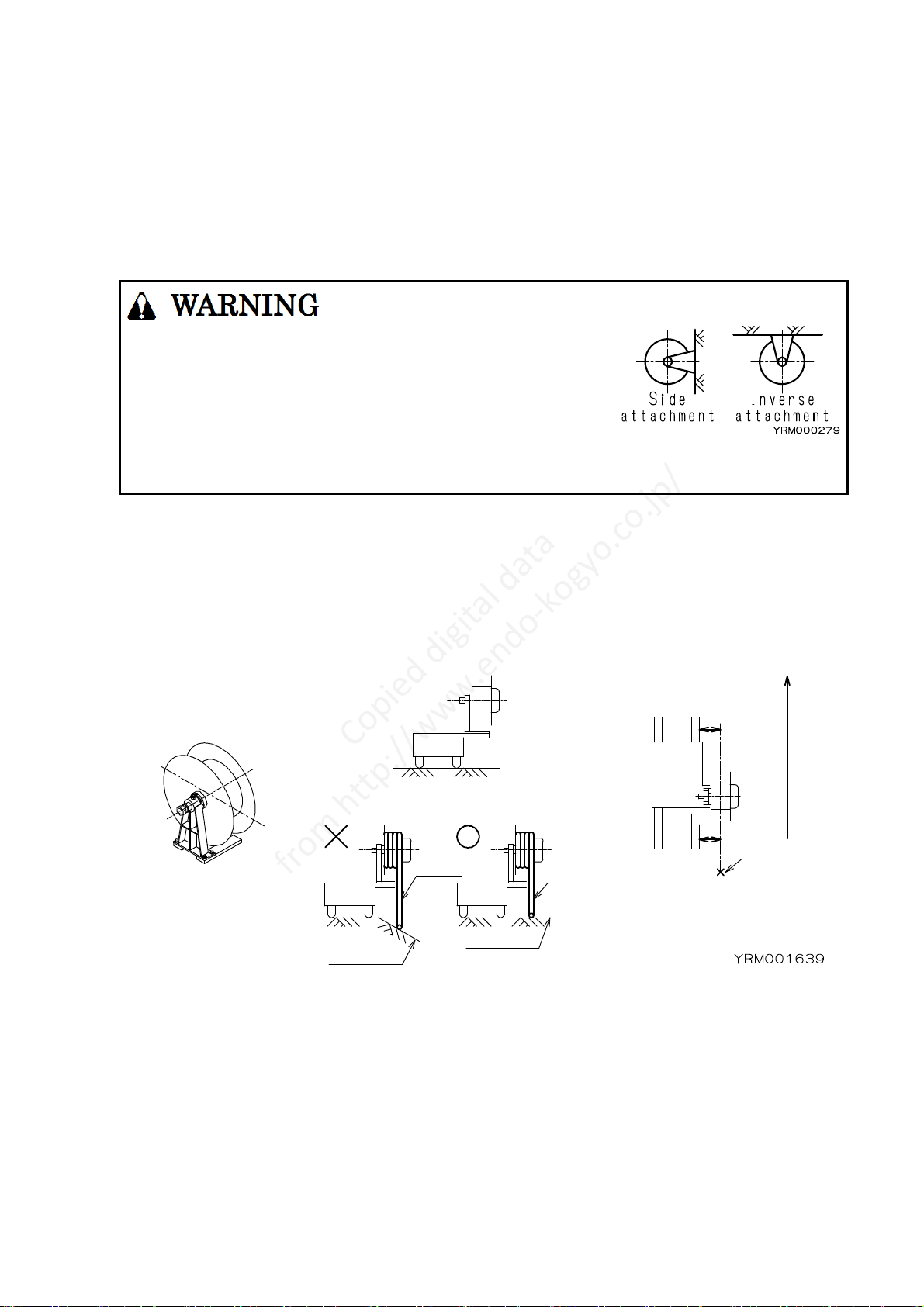
4-2. Installation
Figure 6
・Take sufficient care not to knock or drop the reel
when handling.
When lifting the reel, wrap the belt sling around
the drum at least twice, and lift in stable conditions.
・Never use the arm of the guide roller
(special accessories) to lift the reel.
・For side attachment or inverse attachment, use bolts with a strength
classification above 10.9.
・Place the main body in the fixing location and anchor the bracket securely with 4 bolts.
NOTE: In order to correctly wind the hose adjust the reel position as shown in Figure 7.
Try to adjust so the center of the drum width lines up with the hose's fixed point
on the mating equipment.
The surface the hose lies on should be horizontal.
Figure 7
X axis
Y axis
Moving direction
The Xaxisshould
behorizontal.
TheY axisshouldbeparallel
withthedirectiono
f
the
hosepayoutandmotion
oftheequipment.
Lineupthecenter ofthe
drumwidthwiththehose’s
fixedpointon the
matingequipment.
Fixed point
Hose Hose
Thesurface thehoselieson
should behorizontal.
Surface
Surface
Copied digital data
from http://www.endo-kogyo.co.jp/

- 9 -
5. Hose Connection
5-1. Calculation of required hose length on winding side
Figure 8
Hose length on winding side = Winding length + Extension length + Connection length
+ Dead turn length + Connection length inside reel.
Winding length = The length wound onto the drum.
Extension length = The length from the hose's fixed point to the end of the winding,
which is not wound onto the drum.
Connection length = The length required to connect the mating equipment to the hose's fixed point.
Dead turn length = The length of the 2-3 dead turns.
Required dead turn length = (Drum diameter + Hose diameter) × π×2 ~ 3
Number of dead turns
The length of 1 drum turn
5-2. Hose connection
・Fluid leakage hazard.
Stop supplying the fluid to the hose reel before the work.
・Do not install hose to drum over winding length plus dead turn (2-3 turns).
Make free space in drum, otherwise hose could spill out from drum cover.
If hose spilled, it causes accidents as a hose cutting.
・Connect hose securely to prevent the fluid leakage from connected part.
Winding length
Hose’s fixed point
Mating
equipment
E
x
t
e
n
s
i
o
n
l
e
n
g
t
h
Connection
length
Copied digital data
from http://www.endo-kogyo.co.jp/

- 10 -
Figure 9
■Winding side hose (Refer to Figure 9)
(1) Pass the hose through the drum part from the drum side.
(2) Connect the hose to joint.
NOTE: For hose without fitting, use and tie the sliding band.
Remove nipple for hose with fitting.
Then use seal tape around the screw part of hose fitting.
(Refer to 10)
Figure 10
■Fixed side hose
(1) Attach the hose to spindle.
NOTE: For hose without fitting, use and tie the sliding band.
Remove nipple for hose with fitting.
Then use seal tape around the screw part of hose fitting.
(Refer to Figure 10)
Drum cover
Drum curl part
Joint
Spindle
Fix side hose
Winding side hose
Without fitting With fitting
Hose Hose
Nipple
Hose band Roll seal tape
Bush Bush
JointJoint
YRM001647a
(1)Bush is attached
by specifications.
(2)Use one or two
hose bands
by specification.
(1) (1)
(2)
REMARKS
Copied digital data
from http://www.endo-kogyo.co.jp/
- 11 -
6. Spring Tension Adjustment
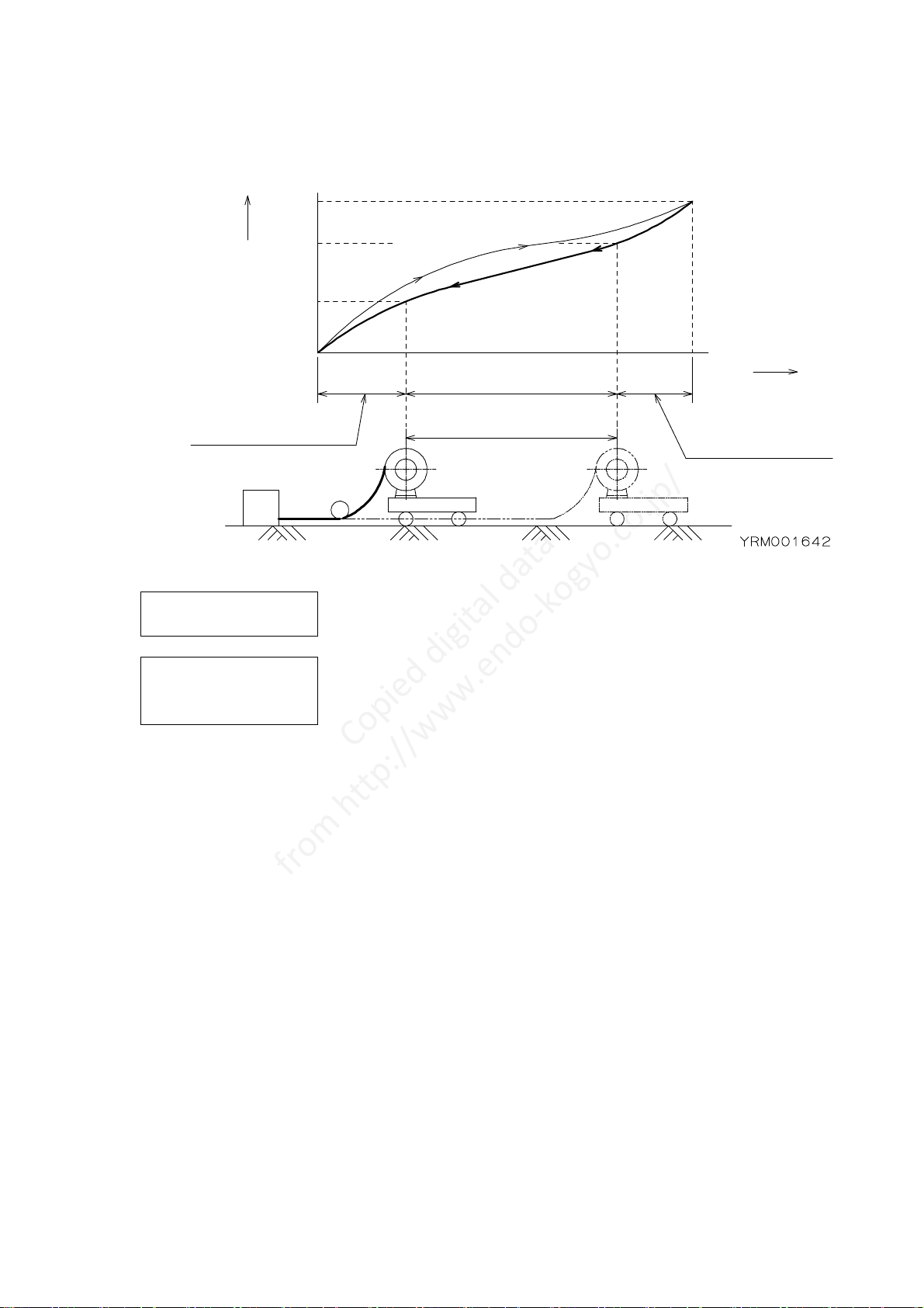
6-1. Relationship between winding torque and drum turns
Figure 11
Number of initial
spring turns means the number of spring turns which provides the initial tension
required for winding the hose onto the drum.
Number of spare
spring turns
means the number of remaining spring turns when the hose is fully paid out.
A shortage of spare spring turns shortens the spring life and causes spring
breakage.
Winding length
Number of drum turns Spring turns
( Drum turns )
Number of initial
spring turns
R
e
c
o
v
e
r
i
n
gt
h
eh
o
s
e
(R
e
l
e
a
s
i
n
gt
h
es
p
r
i
n
g)
P
a
y
i
n
go
u
tt
h
eh
o
s
e
(w
i
n
d
i
n
gt
h
es
p
r
i
n
g)
MAX
MAX
Winding torque
Number of spare
spring turns
Copied digital data
from http://www.endo-kogyo.co.jp/

- 12 -
6-2. Standard value of initial spring turns and calculation for upper limit of initial
spring turns.
(1) Check the total number of spring turns using Table 1 (page 6).
(2) Rotate the drum by hand until the hose of the winding length is fully
retracted, checking the number of drum turns.
(3) Check the standard value of initial spring turns and the number of spare
spring turns using Table 2.
Table 2
Spring
combination Number of sets Standard value of
initial spring turns Number of
spare spring turns
None 1 1 to 3 times 1.5 or more
W 2 2 to 6 times 3 or more
Upper limit of initial spring turns = Total number of spring turns
- (Number of drum turns + Number of spare spring turns)
Example) Model HR-2A305W for the case of 20 drum turns
According to Table 1, Total number of spring turns = 39.
According to Table 2, Standard value of initial spring turns = 2 - 6
Number of spare spring turns = 3 or more
Upper limit of initial spring turns = 39 - (20 + 3) = 16
Then the allowable number of initial spring turns = 2 - 16
6-3. Initial tension setting
・Never let go of the drum during any work.
When released, the drum suddenly rotates, possibly causing personal injury.
・After setting the initial tension, hose connection requires more than
2 people to
secure the drum and connect the hose.
(1) Wind the whole hose around the drum before connecting to the mating equipment.
NOTE: Take care not to twist the hose around the drum.
(2) With the hose still wrapped around the drum, rotate the drum by hand in the payout direction the same
number of turns as “standard value of initial spring turns” (Refer to Table 2).
This becomes "initial spring turn".
(3) Without letting the drum rotate, unwind the hose to the connection length plus the extension length
and connect the hose to the mating equipment.
Check there are no twists in the hose before connection.
(4) Pull out the hose to the winding length, then let the hose wind around the drum.
Ensure the drum can recover the hose full length.
(5) If the drum stops during recovery, the initial spring tension is insufficient.
Disconnect the hose from the mating equipment and increase the number of initial spring turns in the
same manner.
NOTE: Set the initial tension as small as possible and never exceed the upper limit of the initial spring
turns.
Over - tensioning could cause a spring breakage.
Copied digital data
from http://www.endo-kogyo.co.jp/

- 13 -
7. Measure against Uneven Winding
Uneven
winding
means the hose is wound on mainly one side of the drum width.
The uneven winding will cause the hose to drop from the drum or recovery problems,
resulting in damage to the hose.
7-1. Checks before adjustments
(1) Check the reel position is correct.
Refer to Section 4-2. "installation" (page 8).
Adjust the X and Y axes of the reel.
(2) Check there are no twists in the winding side hose.
If the hose is twisted, disconnect the hose from the mating equipment and
remove any twists.
※If uneven winding still exists after the above checks, adjust according to
the next section.
7-2. Adjustments
(1) Initial tension modification.
Increase the number of initial spring turns one by one without exceeding the upper limit.
If there is no improvement, set the initial tension back to the first value.
(2) X axis modification.
Tilt the X axis at a small angle by inserting a spacer under the bracket.
Figure 12
(3) Y axis modification
Tilt the Y axis at a small angle after adjusting the X axis.
Figure 13
Spacer
Spacer
Copied digital data
from http://www.endo-kogyo.co.jp/
- 14 -
8. Safety Instructions on Use
・Never approach the moving parts during operation.
There is a danger of being caught up.
・Before supplying different fluid into the hose, take maker's advise.
If there is no specification request on the type of fluid application, the product
will be for air, water (less than 80ºC), lubricating oil (Mineral type),
grease (lithium type).
If you are applying different kinds of fluid from standard fluid type,take
maker's advise.
・Shut off the fluid supply immediately in case of any trouble to avoid the
problem
escalating.
・Never use the reel when damaged or abnormal sound/vibration occurs.
・Never alter the reel or its accessories.
・Never let go of or unfasten the hose from the fixed points when the hose is
pulled
out.
The hose will rewind suddenly, possibly causing personal injury.
・Use within the rated value of maximum working pressure (1.5Mpa {15kgf/cm2}).
・Never pull out the hose past the winding length.
Always leave 2-3 dead turns on the drum. (To the sign of red tape)
Put sign (red tape) on the 2-3 dead turns when installing or replacing the hose.
9. Special Accessories
Figure 14
Ratchet device
Turn table
Arm type guide rollerStopper
Copied digital data
from http://www.endo-kogyo.co.jp/
- 15 -
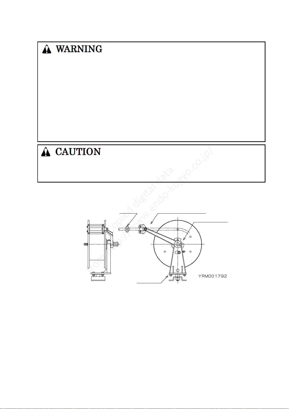
(1) Turn table
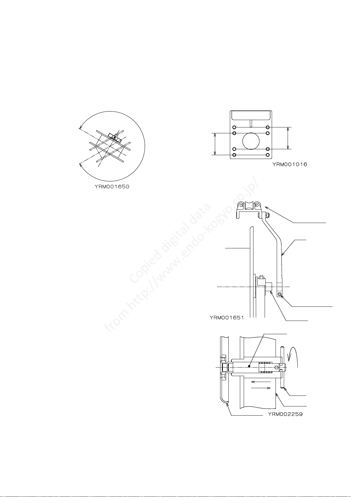
This can swivel the reel up to 300゜(Refer to Figure 15).
When turned, take care the fixed side hose is not put under excessive force or contacts the reel or
surrounding objects.
An arm type guide roller is required together with the turn table.
The fixing position varies depending on the drum width.
Confirm the model name indicated on the name plate, then check the drum code and width. Refer to
Section 3-1. "Model and specifications" (page 5).
Fix the turn table to the bracket with the enclosed 4 bolts and nuts referring to Figure 16.
Figure 15 Figure 16
(2) Arm type guide roller Figure 17
This is required when the reeling direction angle varies
during operation.
Attach the arm to the spindle and fix with the hexagon
socket head cap screw.
(3) Stopper (Hose the attached)
This will stop the hose at the attached location during a
winding operation when used with the arm type guide
roller.
(4) Drum stopper
The rotation of the drum can be locked at 90° intervals.
Pull the lever, turn the stopper and insert it in the hole
of the drum cover. Pull the lever and set it on the
shallow slit for releasing the lock.
(5) Ratchet device (Use for pulling the hose manually) Figure 18
This is used when the winding operation stops and the
hose is still paid out.
To stop the drum, pull out the hose slightly then let it
return.
To release the drum, pull out the hose so as to rotate
the drum by 1/4 turn.
U
pt
o3
0
0
゜
For drum code
of 2A or 3A
For drum code
of 2 or 3
Gude roller
Arm
Spindle
Hexagon spcket
head cap screw
Drum cover
lever
S
t
o
p
p
e
r
Bracket
Copied digital data
from http://www.endo-kogyo.co.jp/
This manual suits for next models
1
Table of contents
Other Endo Tools manuals


Popular Tools manuals by other brands


Huskie Tools
Huskie Tools SL- 610 Operation manual

RIDGID
RIDGID PH-60C Swiv-L-Punch Head instructions

Hilti
Hilti SMD 50 Operating instructions and owner's manual

Hakko Electronics
Hakko Electronics FT-8004 manual

Harrington Hoists
Harrington Hoists ER2 Series Owner's manual supplement
Piper
Piper CHEROKEE ARROW III Information manual


