endolite Elite2 User manual

Elite2
EN Instructions for Use 2
FR Instructions D’Utilisation 14
DE Gebrauchsanweisung 26
IT Istruzioni per L’Uso 39
ES Instrucciones de Uso 51
EL24L1–EL30R9
EL24L1D–EL30R9D
EN
2
938223/13-0717
User weight
Foot spring
set
Impact
Activity
44–52
(100-115)
53–59
(116-130)
60–68
(131-150)
69–77
(151-170)
78–88
(171-195)
89–100
(196-220)
101-116
(221-255)
117-130
(256-285)
131-147
(286-325)
148-166
(326-365)
kg
(lb)
Low 31123456789
Mod4123456789
High423456789
Important:
For higher impact users, do not exceed the
weight limit for individual springs.
Low Daily walking and occasional sports such
as golf and hiking
Moderate Aggressive walking, frequent or daily
sports such as jogging
High Daily activities such as distance running,
climbing, lifting and carrying heavy
objects for vocational purposes
Application
These instructions for use are for the practitioner.
The term device is used throughout these instructions for use to refer to Elite2.
This device is to be used exclusively as part of a lower limb prosthesis.
A high-energy-return foot. The independent heel and toe springs provide axial deection. The
split toe provides good ground compliance.
This device is recommended for users that have the potential to achieve Activity Level 3 or 4. Of
course there are exceptions and in our recommendation we want to allow for unique, individual
circumstances and any such decision should be made with sound and thorough justication.
Appropriate footwear must be worn to avoid the risk of slipping in
wet environments.
Contra-indications
This device might not be suitable for Activity Level 1 individuals or for competitive sports events,
as these types of users will be better served by a specially designed prosthesis optimized for their
needs.
Intended for a single user.
Ensure that the user has understood all instructions for use, drawing particular attention to the
section regarding maintenance.
1 Description and Purpose
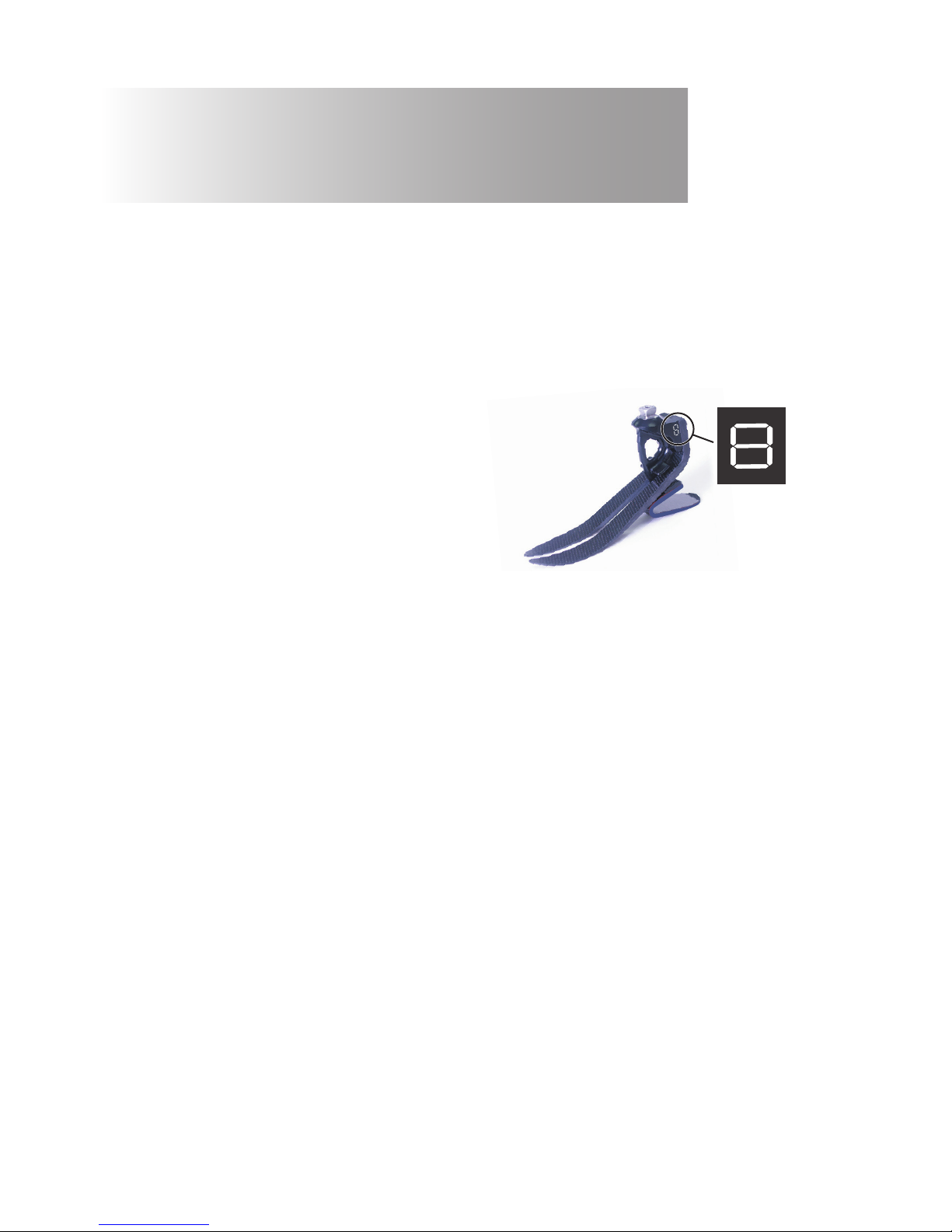
Spring set selection

3
938223/13-0717
When tted with springs, cover appropriate
lines on carrier with permanent black marker
to leave spring set number showing.
Note:
If in doubt choosing between two categories, choose the higher rate spring set.
Foot Spring set recommendations shown are for trans-tibial users.
For trans-femoral users we suggest selecting a spring set one category lower,
refer to tting advice Section 7 to ensure satisfactory function and range of movement
Has the ability or potential for ambulation with variable cadence.
Typical of the community ambulator who has the ability to traverse most
environmental barriers and may have vocational, therapeutic, or exercise activity
that demands prosthetic utilization beyond simple locomotion.
Activity Level 3

4
938223/13-0717
Principal parts:
• Carrier Assembly (aluminum/St. Stl./titanium)
• Heel & Toe Springs (e-Carbon)
• Spring Attachment Screws (titanium)
• Glide Sock (UHM PE)
• Foot Shell (PU)
2 Construction
Glide
Sock
Foot
Shell
Toe Spring
Carrier
Heel
Spring
Heel Spring
Screws
Toe Spring
Screw
4
15Nm
13A/F
25Nm
(cat 8&9)
4
15Nm
(cat 1–7)
Heel Wedge

5
938223/13-0717
3 Function
This device comprises an e-carbon toe and independent heel spring.
Heel and toe springs are attached to the carrier using titanium screws. The foot is wrapped in a
UHM PE sock which is in turn surrounded by a PU foot shell.
4 Maintenance
5 Limitations on Use
Maintenance must be carried out by competent personnel.
We recommend the following annual maintenance:
• Remove the foot shell and glide sock, check for damage or wear and replace if necessary.
• Check all screws for tightness, clean and reassemble as necessary.
• Check heel and toe springs for signs of delamination or wear and replace if necessary. Some
minor surface damage may occur after a period of use, this does not aect the function or
strength of the foot.
The user must be handed the user information card supplied, and be advised of the following:
• Any changes in performance of this device must be reported to the practitioner
e.g. reduced energy return or unusual noises.
• The practitioner must also be informed of any changes in body weight and/or activity level.
If this device is used for extreme activity, the maintenance level and interval should be reviewed
and if required advice and technical support sought to plan a new maintenance schedule
dependent upon the frequency and nature of the activity. This should be determined by a local
risk assessment carried out by a suitably qualied individual.
Cleaning
Use a damp cloth and mild soap to clean outside surfaces, do not use aggressive cleansers.
Intended life
A local risk assessment should be carried out based upon activity and usage.
Lifting loads
User weight and activity is governed by the stated limits.
Load carrying by the user should be based on a local risk assessment.
Environment
This device is waterproof to a maximum depth of 1 meter.
Thoroughly rinse this device with fresh water after use in abrasive environments such as those
that may contain sand or grit, for example, to prevent wear or damage to moving parts.
Thoroughly rinse with fresh water after use in salt or chlorinated water.
Foot units must be adequately nished to prevent water ingress into the foot shell where
possible. If water enters the foot shell, it should be inverted and dried before further use.
Exclusively for use between -15˚C and 50 ˚C.
We recommend using Endolite products with this device.

0-10mm
½½
6
938223/13-0717
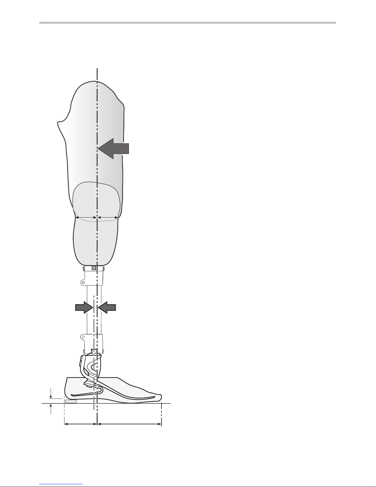
6 Bench Alignment
Static alignment
Setup length
With exion, adduction and abduction
properly accommodated, set the limb length
5mm longer than the sound side to allow for
compression and deection of the foot springs
during gait. This should be re-assessed once
the dynamic trial commences and the length
adjusted accordingly.
Build line
This should fall 10mm anterior to the centre
of the pyramid (with heel height properly
accommodated). The socket should be
positioned accordingly.
Dynamic alignment
Coronal plane
Ensure that M-L thrust is minimal by adjusting
relative positions of socket and foot.
Saggital plane
Check for smooth transition from heel strike
to toe-o. Ensure also that when standing the
heel and toe are evenly loaded and that both
are touching the oor.
Trans-femoral alignment
Align trans-femoral components according
to tting instructions supplied with the knee,
keeping the build line relative to the foot as
shown.
Build
Line
Approx.
1/3 2/3
Allow for users
own footwear
**

7
938223/13-0717
7 Fitting Advice
Spring sets are supplied as matched pairs i.e. the heel and toe spring are designed to work
together to give smooth progression for most users.
Heel wedge
A heel wedge is supplied with the foot. Fitting the wedge will have the eect of stiening the
heel spring. These can be taped in place for trial. For permanent tting, wedges should be
adhered in place by application of Loctite 424 (926104) between the lower contacting surface of
the heel and the wedge.
Heel stiness
Progression throughout the stance phase should be smooth; heel function is key to this process:
• Too soft a heel or load line excessively posterior will result in sinking at heel strike and
diculty in getting over the toe.
• Too hard a heel or load line excessively anterior will result in a rapid progression through
mid-stance or jarring at heel strike.
Symptoms Remedy
Heel too soft
• Sinking at heel strike
Diculty climbing over the toe
(toe feels too hard)
1. Add heel wedge
2. Move socket anteriorly in relation to
the foot
(excess movement may result in drop
o)
3. If 1 and 2 fail, t a stier spring set
Heel too hard
• Rapid transition from heel strike
through stance phase
Diculty in controlling heel
action, foot jars into mid-stance
• Foot feels too rigid
1. Remove heel wedge (if tted)
2. Move socket posteriorly in relation to
foot
3. If 1 and 2 fail, t softer spring set
Please contact your supplier if it is not possible to achieve a smooth gait after following the advice above.
8
938223/13-0717
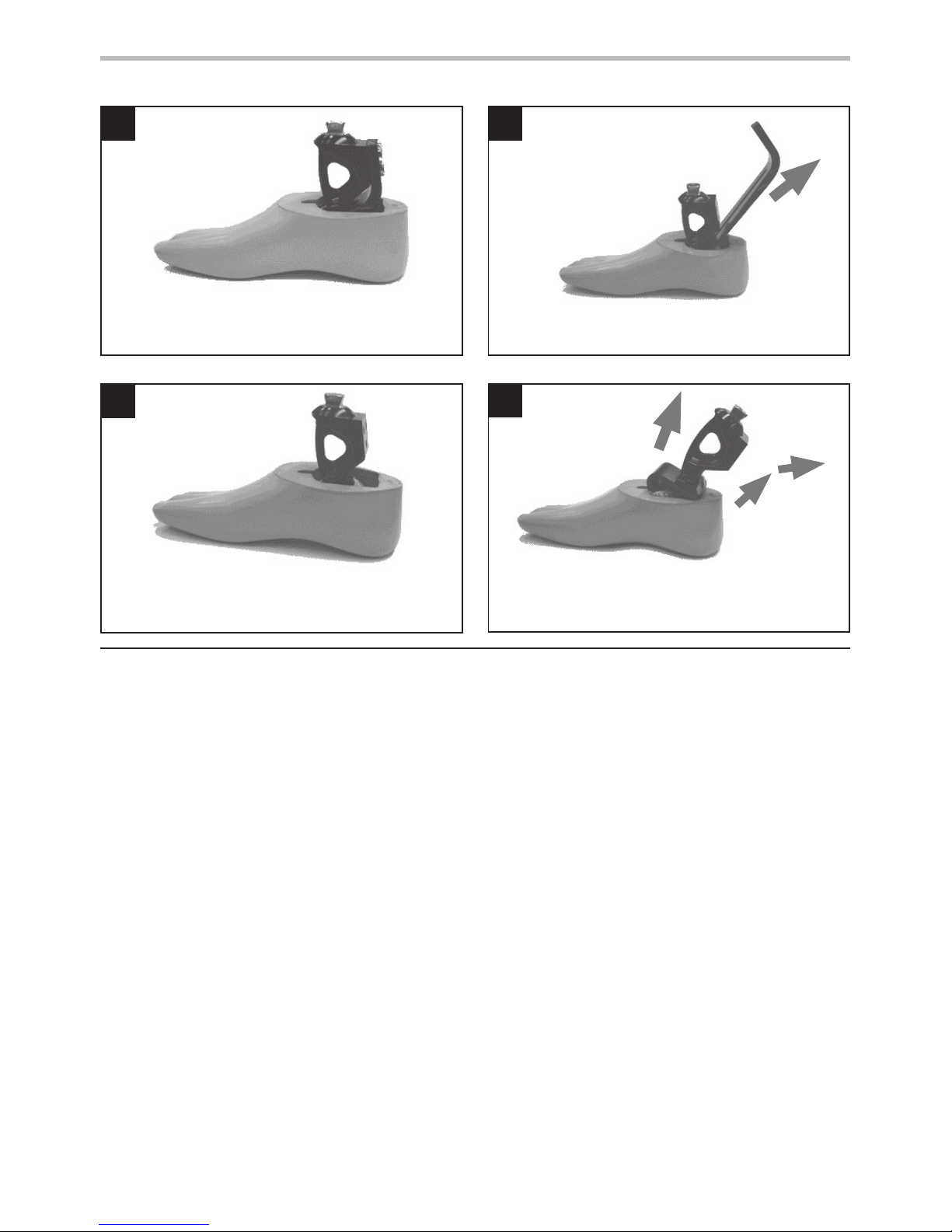
1
Carefully remove, with a knife, any foam cosmesis
that may be adhered to the foot shell.
2
Remove securing screws from the carrier and
pull the toe spring towards the rear of the foot.
34
Remove the toe spring to leave the carrier/heel
spring assembly alone inside the foot shell.
Rotate the carrier/heel spring assembly toward
the rear of the foot to dis-engage the spring from
it’s location in the shell.
8 Dis-assembly Instructions

5
2
4
1
3
9
938223/13-0717
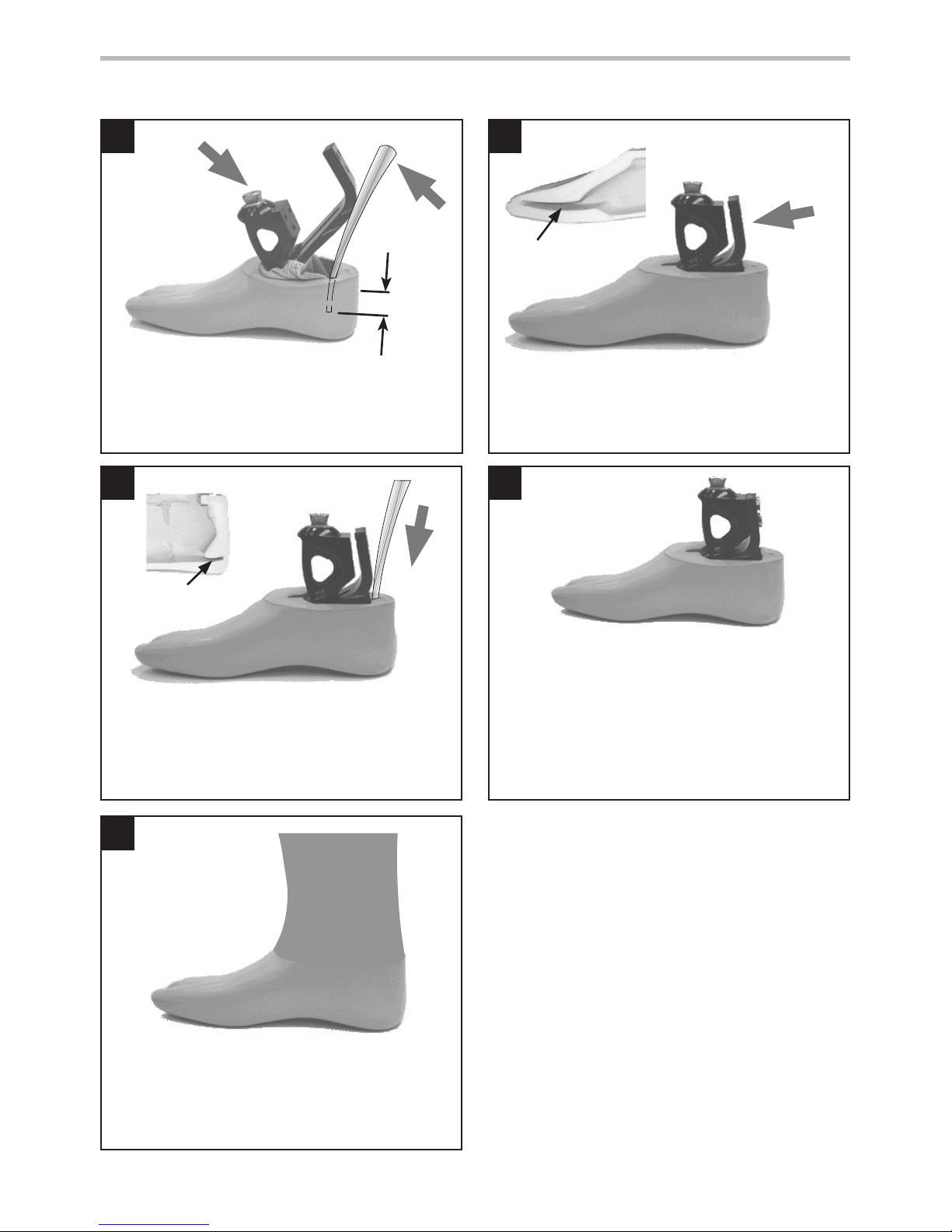
9 Assembly Instructions
Assemble heel spring onto carrier, use Loctite
243 (926012) and torque to 15Nm. Use special
Allen wrench 940080, Torque spanner adaptor
940081 or 13A/F spanner 940273.
Heel
spring
Carrier
Glide
sock
Unwrap the
glide sock
onto the toe
spring
Unwrap glide sock over heel spring as shown.
Slide toe spring into position on carrier (do
not assemble bolts). Fold the glide sock neatly
around the end of the toe.
If a foam cosmesis is to be tted, roughen top
surface of foot shell to provide ideal bonding
surface.
Push toe spring forward as far as possible. Slide carrier/heel spring assembly forward into
slot in top of foot shell.
slot in
foot shell
6
11
7
9
8
10
10
938223/13-0717
9 Assembly Instructions (continued)
Slide a metal shoe horn between heel spring and
back of foot shell opening and lever the spring
down into the foot shell.
Push toe spring towards carrier. Ensure glide sock
doesn’t get trapped between the spring and
carrier. Push spring into location in shell.
Press heel spring into location in shell as shown.
Attach the toe spring to the carrier using Loctite
243 (926012) on the bolts.
1. For spring rates 1 to 7 use 4 A/F Allen wrench
and torque to 15Nm. Do not use external
hex, this is reserved for loosening the bolt, if
required.
2. For spring rates 8 and 9 use 13 A/F spanner
and torque to 25Nm.
Bond foam cosmesis to top surface of the foot
shell as shown using Thixox adhesive (926204)
or equivalent and shape to suit.
30mm
below heel
Toe spring
location
in foot shell
heel spring
location slot

11
938223/13-0717
Fitting length
10 Technical Data
Operating and
Storage Temperature Range:
-15˚C to 50 ˚C
(5˚F to 122 ˚F)
Component Weight (size 26): 395g ( 14oz)
Activity Level: 3–4
Maximum User Weight: 166kg (365lb)
Proximal Alignment Attachment: Male Pyramid (Endolite)
Range of Adjustment: ±7° Angular
Build Height:
(See diagram below)
130 mm
Heel Height: 10mm
* sizes
24–28 = 70mm
29–30 = 80mm
130mm
10mm
*

12
938223/13-0717
11 Ordering Information
Spring kit Foot size
24–26 27–28 29–30
Set 1 539710 539719 Special order
Set 2 539711 539720 Special order
Set 3 539712 539721 539730
Set 4 539713 539722 539731
Set 5 539714 539723 539732
Set 6 539715 539724 539733
Set 7 539716 539725 539734
Set 8 539717 539726 539735
Set 9 539718 539727 539736
Spring kit
Foot shell
Left
24L 539005
25L 539007
26L 539009
27L 539011
28L 539013
29L 539015
30L 539017
Right
24R 539006
25R 539008
26R 539010
27R 539012
28R 539014
29R 539016
30R 539018
Glide Sock
One size ts all Part No. 532811
For dark add ‘D’
Available from size 24 to size 30:
EL24L1 to EL30R9
EL24L1D to EL30R9D
Size
Side
Spring Set
Category
Order example
e.g. EL25L3
(add ‘D’ for a dark tone foot shell)
EL 25L 3

13
938223/13-0717
This product meets the requirements of 93/42/EEC guidelines for medical products. This product
has been classied as a Class 1 Product according to the classication criteria outlined in
Appendix IX of the guidelines. The Declaration of Conformity was therefore created by Blatchford
Products Limited with sole responsibility according to Appendix VII of the guidelines.
The manufacturer recommends using the device only under the specied conditions and for the
intended purposes. The device must be maintained according to the instructions for use supplied
with the device. The manufacturer is not liable for damage caused by component combinations
that were not authorized by the manufacturer.
Liability
CE Conformity
Warranty
Blatchford Products Ltd. and ENDOLITE are companies and trademarks of Chas. A. Blatchford and Sons Ltd.
This device is warranted for 36 months - foot shell 12 months - glide sock 3 months.
The user should be aware that changes or modications not expressly approved could void the
warranty, operating licences and exemptions.
See Endolite website for the current full warranty statement.
FR
14
938223/13-0717
Poids de l’utilisateur
Catégories de
jeux de lames
de pied
Impact
Activité
44–52
53–59
60–68
69–77
78–88
89–100
101-116
117-130
131-147
148-166
kg
Faible31123456789
Modéré 4123456789
Fort 423456789
Important: pour les utilisateurs à impact
plus fort, ne pas dépasser la limite de poids
de chaque lame.
Faible Marche quotidienne et sport occasionnel
de type golf et randonnée
Modéré Marche aggressive, sports fréquents ou
quotidiens de type course à pied
Fort Activités quotidiennes telles que course
sur longue distance, escalade, levage et
transport d’objets lourds dans un cadre
professionnel
Application :
Ces instructions sont destinées à l’attention de l’orthoprothésiste.
L’Elite2 doit être utilisé dans le cadre d’une prothèse de membre inférieur.
Pied avec forte restitution d’énergie. Le talon indépendant et les ressorts d’orteils procurent une
déexion axiale. L’orteil divisé procure une bonne adhérence au sol.
Cette prothèse est recommandée aux amputés qui ont la possibilité d’atteindre un niveau
d’activité 3 ou 4. Bien évidemment il existe des exceptions et nous conseillons de prendre en
considération les circonstances uniques et personnelles de chacun et de décider après mûre
justication.
Portez des chaussures appropriés pour éviter le risque de chute dans un
environnements humides et glissant
Contre-indications:
Ce dispositif peut ne pas convenir aux individus au niveau d’activité 1 ou aux patients
participant à des manifestations sportives de compétition, car ces utilisateurs seront mieux
servis par une prothèse spéciquement conçue et optimisée pour leurs besoins.
Prévu pour un utilisateur individuel.
Veiller à ce que le patient ait bien compris toutes les instructions d’utilisation et porter une
attention particulière à la section concernant l’entretien.
1 Description et objectif
Choix du jeu de Lames
15
938223/13-0717
Une fois les lames montés, colorier les
lignes appropriées du support au marqueur
permanent noir an d’acher la catégorie du
jeu de lames.
Note:
En cas de doute entre deux catégories de lames, choisir la plus dure.
Les recommandations de jeux de lames repésentés sont pour un patient amputé tibial.
Pour un amputé fémoral nous conseillons de prendre la catégorie en dessous tout en
veillant à respecter les grilles de poids. Se référer à la section 7 de la notice de montage
pour assurer une fonction et une amplitude satisfaisante.
A la capacité ou le potentiel pour se déplacer à des cadences variables.
Typique des patients aptes à gérer la majorité des obstacles
environnementaux et pouvant avoir une activité professionnelle ou
thérapeutique qui exige l’utilisation d’une prothèse au-delà de la
simple locomotion.
Activité 3

16
938223/13-0717
2 Construction
Composants principaux :
• Châssis (aluminium/acier inox/ titane et acier)
• Lames de talon et d’avant pied (E-Carbon)
• Vis de xation de lames (titane et acier)
• Chaussette de protection (UHM PE)
• Enveloppe de pied (PU)
Chaussette de
protection
Enveloppe de
pied
Lame
d’avant pied
Ensemble
support
Lame de talon
Vis de lame
de talon
Vis de lame
d’avant
4
15Nm
13A/F
25Nm
(cat 8&9)
4
15Nm
(cat 1–7)
Cale de talon

17
938223/13-0717
L’Elite2 est constitué d’un orteil en e-carbone et d’une lame de talon indépendante. Les lames de
talon et d’avant-pied sont xées au support par des vis en titane. Le pied est enveloppé dans une
chaussette en PE UHM qui est insérée dans une enveloppe de pied en PU.
Durée de vie prévue :
Une évaluation des risques locaux doit être eectuée en fonction de l’activité et de l’utilisation.
Port de charges :
Le poids et l’activité de l’amputé sont régis par les limites indiquées.
Le port de charges par l’amputé doit être basé sur une évaluation des risques locaux.
Environnement :
Le produit est étanche sur une profondeur maximale de 1 mètre.
Rincez abondamment à l’eau claire après utilisation dans un environnement abrasif comme
ceux susceptibles de contenir du sable ou des gravillons, par exemple, pour prévenir l’usure ou
d’endommager les pièces mobiles;
Rincez abondamment à l’eau claire après utilisation dans de l’eau salée ou dotée de chlore.
Les éléments de pied doivent bénécier d’une nition adéquate pour empêcher l’eau de
pénétrer dans l’enveloppe de pied autant que possible. Si de l’eau pénètre dans l’enveloppe, le
dispositif doit être retourné et séché avant une nouvelle
utilisation.
Exclusivement pour une utilisation de -15°C à 50°C.
On recommande de n’utiliser que les produits Endolite
avec Elite2.
3 Fonction
4 Entretien
5 Limites d’utilisation :
L’entretien doit être eectué par du personnel qualié.
Il est recommandé d’eectuer l’entretien suivant chaque année:
• Retirer l’enveloppe esthétique du pied et la chaussette de protection. Les vérier et s’il existe
des traces de dommage ou d’usure les remplacer.
• Vérier le serrage de toutes les vis, nettoyer et remonter, si nécessaire.
• Contrôler visuellement les lames de talon et d’avant pied pour déceler tous signes de
délamination ou d’usure : les remplacer si nécessaire. Des dégâts mineurs en surface peuvent se
produire après une période d’utilisation, cela n’aecte pas la fonction ou la résistance du pied.
La che d’utilisation doit être remise à l’utilisateur et ce dernier doit être informé de ce qui suit:
• Tout changement des performances de ce dispositif doit être signalé à l’orthoprothésiste.
(Par exemple, une diminution de la restitution d’énergie ou des bruits inhabituels.)
• L’orthoprothésiste doit également être informé de tout changement dans le poids corporel
et / ou le niveau d’activité du patient.
Si ce produit est utilisé pour une activité extrême, l’intervalle et le niveau d’entretien doit être
revu. En fonction de la nature et de la fréquence de cette activité un nouveau calendrier de
suivi devra être établi. Celui-ci pourra être déterminé après une évaluation locale des risques
eectuée par une personne dûment qualiée.
Nettoyage :
Utiliser un chion humide et un savon doux pour nettoyer les surfaces extérieures; n’utiliser pas
de détergent agressif.
0-10mm
½½
Prendre en compte la hauteur de
talon de la chaussure de l’utilisateur
18
938223/13-0717
6 Alignement
Alignement statique
Dénir la hauteur
Une fois la exion, l’aduction et l’abduction
dûment réglées, xer la hauteur de l’appareil
à 5mm de plus que le membre sain an
depermettre la compression et la détente des
lamesdu pied lors de la marche. Ce réglage
doit êtreréévalué après les tests dynamiques et
lalongueur réajustée en fonction.
Ligne de charge
Celle-ci devrait tomber entre la ligne centrale
dela pyramide et 10mm plus en avant (le
poids dupatient étant correctement réparti).
L’emboîturedoit être positionnée en fonction.
Alignement dynamique
Plan frontal
Vérier que le mouvement M-L est minimal
enréglant les positions respectives de
l’emboîture etdu pied.
Plan sagital
Vérier que la transition depuis l’attaque du
talon jusqu’a la phase d’élan est souple et
continue. Vérier aussi qu’en position debout,
le poids estégalement réparti entre le talon et
l’avant du pied et que les deux sont en contact
avec le sol.
Alignement fémoral
Aligner les dispositifs fémoraux selon les
instructions de montage fournies avec le
genou, en maintenant l’axe de montage par
rapport à l’Elite2 comme sur le schéma.
Ligne de
charge
Environ
1/3 2/3
**

19
938223/13-0717
7 Conseils de réglages
Veuillez contacter le fournisseur si vous n’obtenez pas une démarche souple même en appliquant les conseils
ci-dessus.
Les jeux de lames Elite2 sont fournis par paires, la lame de talon et celle d’avant pied sont
conçus pour fonctionner ensemble an d’assurer à la plupart des personnes amputées un
fonctionnement confortable.
Cale de talon
Une cale de talon est fournie avec le pied. Le montage de la cale durcira la lame de talon.
Elle peut être scotchée en place pour un essai. Le montage dénitif des cales doit se faire par
application de Loctite 424 (926104) entre la surface de contact inférieure du talon et la cale.
Rigidité du talon
La progression lors de la phase d’appui doit être souple ; la fonction du talon est essentielle à ce
processus:
• Un talon trop souple ou une ligne de charge trop en arrière peuvent entraîner un
aaissement du talon et une diculté à passer sur l’avant du pied.
• Un talon trop rigide ou une ligne de charge trop vers l’avant peuvent entraîner un passage
rapide en phase d’appui intermédiaire ou un choc lors de la pose du talon.
Symptômes Remède
Talon trop souple
• Aaissement lors de l’attaque
du talon
• Diculté à passer sur l’avant du
pied (les orteils semblent trop
durs)
1. Translater l’emboîture plus vers l’avant
du pied
(un mouvement excessif peut entraîner
un glissement)
2. Mettre un ensemble de ressort plus dur
3. Si 1 et 2 ne fonctionnent pas, monter un
jeu de lames plus durs
Talon trop dur
• Transition rapide de l’attaque du
talon à la phase d’appui
Diculté à contrôler l’action du
talon, rotation du pied ou marche
en 2 temps
• Le pied semble trop rigide
1. Translater l’emboîture plus vers l’arrière
du pied
2. Mettre une lame plus souple
3. Si 1 et 2 ne fonctionnent pas, monter un
jeu de lames plus mous

20
938223/13-0717
12
34
8 Instructions de démontage
Enlever soigneusement, avec un couteau, toute
la mousse esthétique qui peut adhérer à l’
enveloppe de pied.
Enlever les vis de xation du support et tirer la
lame d’avant pied vers l’arrière.
Enlever la lame d’avant pied pour laisser
l’ensemble support/lame de talon seul à
l’intérieur de l’enveloppe de pied.
Tourner l’ensemble support/lame de talon vers
l’arrière du pied pour dégager la lame de son
emplacement dans l’enveloppe.
Table of contents
Languages:
Popular Mobility Aid manuals by other brands


Cefndy
Cefndy Zenith Bariatric Commode X148 User instruction

Decon wheel
Decon wheel G5 Modulair Assembly instructions

Guldmann
Guldmann GH Service guide

Heartway Medical Products
Heartway Medical Products QUEST user manual

Winncare
Winncare Mangar Swift User instructions

Petermann
Petermann Alpha Bed Wedges manual


