Guldmann GH User manual

23W123W1
GENERAL INFORMATION
SERVICE AND REPAIR
TECHNICAL DRAWINGS
CONTROL
Guldmann develops, manufactures,
distributes and maintains products and
services that make the daily lives
of disabled people and their
carer a little easier.
SERVICE GUIDE
FOR GH
Vers. 3.00

© Guldmann GB/US-09/2016 • #550376_3
4
GENERAL INFORMATION
General conditions ................................6
Key to symbols and general information ...............8
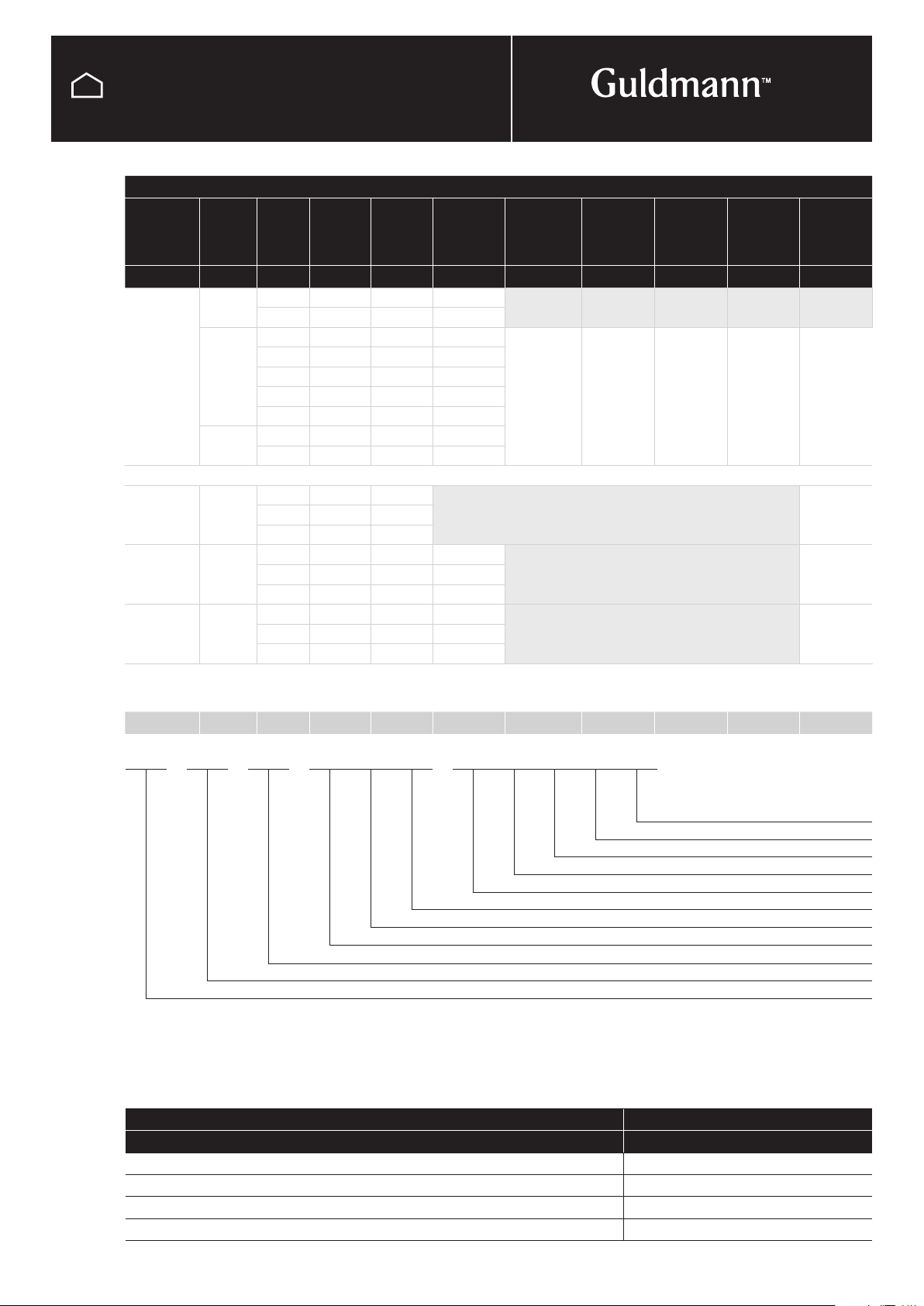
GH lifting modules, configurations ....................9
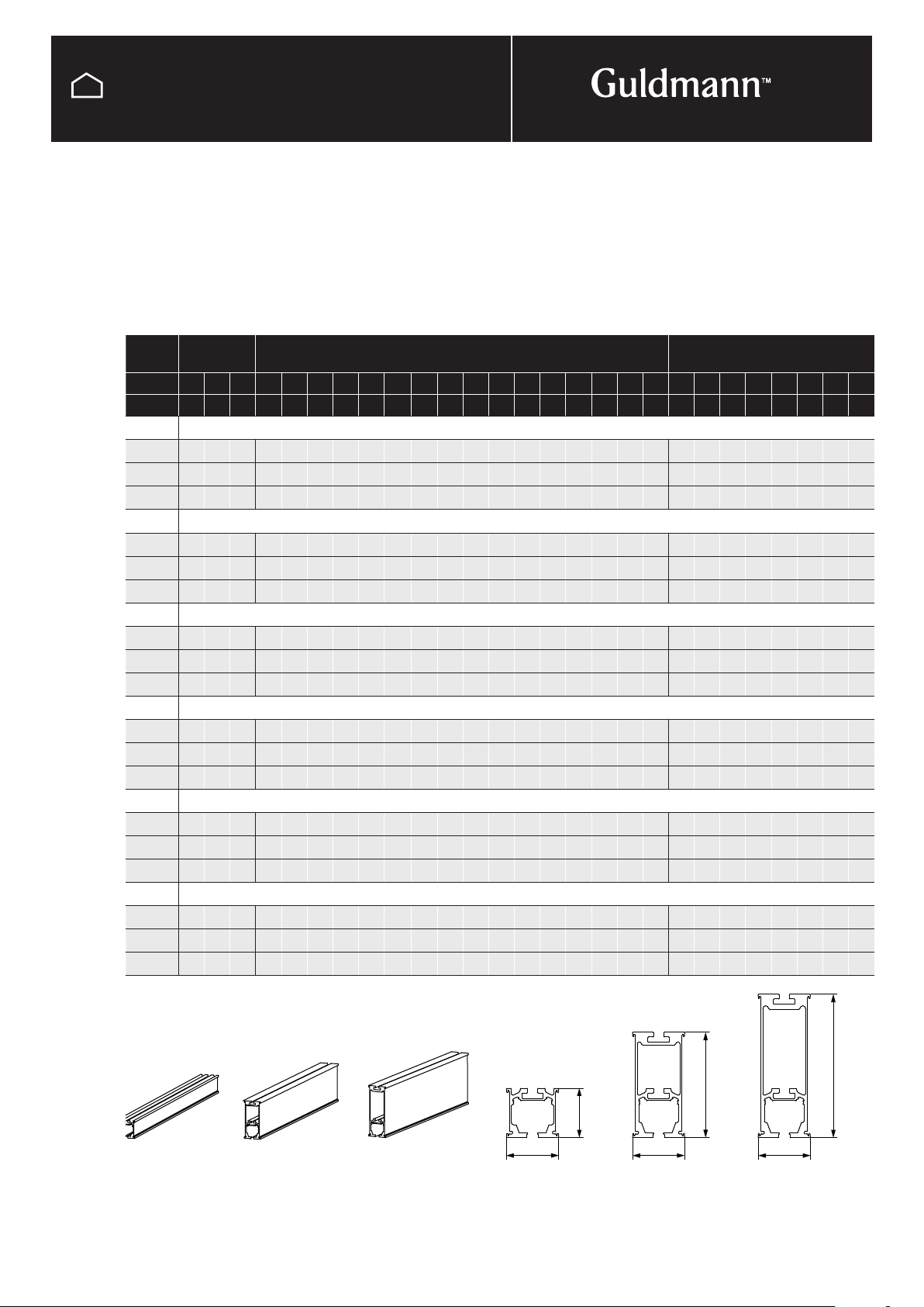
Types of rail .....................................10
GH3 & GH3+ .................................10
GH1 ........................................11
Technical specifications ...........................12
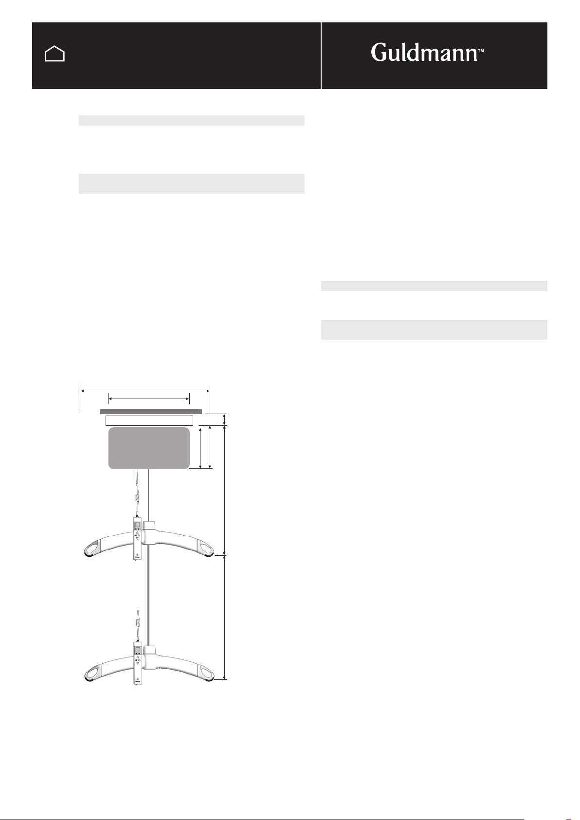
GH3 and GH3+ ...............................12
GH3 Twin ....................................13
GH1 ........................................14
GH1 F .......................................15
GH1 Q ......................................16
Trolley and Transport trolley for GH1 F .............17
Power supply....................................18
Electrical installations
Protection against electric shock ....................19
SERVICE AND REPAIR
GH3 ..........................................24
Before service or repair starts ....................24
Removing side covers ..........................25
Removing hoist from trolleys .....................26
Replacement of batteries - 1 drive belt .............27
Replacement of batteries - 2 drive belt .............28
Replacement or adjustment of hand control.........29
Replacement of lifting strap ......................32
Replacement of timing belt ......................35
Removing covers ..............................36
Replacement of safety control mechanism ..........38
Replacement of belt drive .......................39
Coating at GH1/GH3 during annual inspection.......41
Replacing or adding PCBs ......................42
Replacing the leader motor safety PCB ............43
Replacing the Auxiliary motor PCB ................45
Replacement a Communication PCB ..............46
Replacement of charger PCB ....................47
550548_01 Motor safety 2010 PCB, spare part ......48
550550_00 Communication PCB, addition ..........53
552714_01 Motor AUX, Spare part ................56
Wi-Fi PCB, Spare part ..........................59
WiFi sequence ................................60
WiFi description ...............................61
Installation of Wi-Fi PCB.........................62
Adjusting the bottom cover ......................64
Product and Wi-Fi Label ........................65
Upgrade GH3+ ...............................66
Cover cut-out instruction ........................67
GH1 ..........................................68
Before service or repair starts ....................68
Removing the side covers .......................69
Removing the Trolleys, GH1 & GH1Q ..............70
Removing top assambly, GH1F...................71
Removing the hoist covers.......................73
Replacing Battery ..............................74
Replacing the lifting strap .......................75
Replacing the Hand control ......................77
Replacing safety control mechanism...............78
Replacing the timing belt ........................79
Replacing belt drive ............................80
Replacing the charge PCB.......................81
Replacing the Motor safety PCB ..................82
Instructions for installing PCB and Battery unit .......83
GH1 F Trolley recomendations ...................89
Battery storage NiMH .............................90
IR remote control. . . . . . . . . . . . . . . . . . . . . . . . . . . . . . . . .91
Guidelines for troubleshooting ......................95
GH Combi lock ..................................98
Combi lock 3...................................103
Installing non-fric tape, fixed part.................109
Switch track GH ................................110
End stop ......................................125
Swivel assembly instruction .......................126
TECHNICAL DRAWINGS
Spare part overview .............................128
GH3+ .....................................128
GH3 .......................................130
GH3 twin....................................132
GH1 & GH1 Q ...............................133
GH1 F ......................................135
Wiring Diagram .................................137
GH3 200 kg & 250 kg .........................137
GH3 200 kg & 250 kg drive .....................138
GH3 Twin 250 kg & 500 kg .....................139
GH3+ 200 kg & 250 kg ........................140
GH3+ 200 kg & 250 kg drive ...................141
GH3+ 200 kg & 250 kg drive WiFi ...............142
GH3+ 300 kg, 350 kg & 375 kg drive .............143
GH3+ 300 kg, 350 kg & 375 kg drive WiFi .........144
GH3+ Twin 250 kg & 500 kg CLM ...............145
GH3+ Twin 250 kg & 500 kg load cell ............146
GH3+ Twin 250 kg & 500 kg CLM WiFi ...........147
GH3+ Twin 250 kg & 500 kg load cell WiFi ........148
GH1 .......................................149
GH1 F ......................................150
GH1 Q .....................................151

© Guldmann GB/US-09/2016 • #550376_3
5
Jumper settings ................................152
GH3 & GH3+ ................................152
GH3 & GH3+ Twin............................153
GH1, GH1 Q and GH1 F .......................154
Electrical diagram ..............................155
Switch track GH ..............................155
Combi-lock 3, single electrical...................156
Combi-lock 3, double electrical ..................157
Turn tabel GH ................................158
GH Horizontal traverse Drive Motor...............159
CONTROL
Checklist ......................................162
Hoist and rail systems .........................162
Slings ......................................164

© Guldmann GB/US-09/2016 • #550376_3
6
GENERAL INFORMATION
General conditions
Product liability
In relation to product liability the current rules under Danish
law shall apply.
The Seller shall never be held liable for operating losses,
loss of earnings and other indirect losses.
Product liability insurance which includes cover against
injury and property damage has been taken out.
Any disputes between the parties shall be settled by the
Maritime and Commercial Court in Copenhagen (Sø- og
Handelsretten) in pursuance of Danish law
Transport and storage
Transport and storage must be in the range of limited
environmental condition:
Temperature between -10 and +40°C / 14 and 104°F
Relative air humidity between 30 and 70 %
Air pressure between 70 and 106 kPa
(See symbols page 8)
Warning!
Do not modify this equipment without authorization of the
manufacturer.
Installation in corrosive surroundings
Special guidelines must be observed when installing the
rail system around swimming pools, etc.
The surfaces of the brackets used, traverse travelling
trolleys, etc., must be painted. Hoists must be supplied
with a special surface treatment.
All fixing elements, nuts, washers, threaded rods, must be
acid-proof.
Acid-proof threaded rods and dual-component adhesive
must be used for installation in concrete, tiles, etc.
Through-going threaded rods or acid-proof screws must
be used for installation in wood.
Particular care should be taken to avoid damaging the
surface of painted components.
Washers made of synthetic material must be used in
between painted surfaces and nuts and ordinary washers.
Damaged paint must be repaired after installation, and
visible threaded rods, nuts, washers, etc., must be covered
with paint.
Hidden threaded rods, nuts, washers, and brackets in the
rail track must be treated with a silicone coating.
Wherever possible, nuts must be fitted with protective
caps.
There must be no swarf, dirt, or other impurities in the
rail system as they will accumulate moisture and lead to
corrosion.
Bearings in traverse travelling trolleys must be treated with
a silicone coating before installation.
Guldmann recommends that in corrosive surroundings like
swimming pools, bathing environments etc., regular safety
and service inspection at rail systems and ceiling hoists
must be performed every ½ year. A complete overhaul of
the rail system (replacements of brackets, fixings etc.) can
be necessary approx. every 5 year.
Guldmann products are designed for use in these environ-
ments with the following maximum values of;
Water quality:
pH....................................... 7,6
Free chlorine, mg/l .......................... 2,0
Bound chlorine, mg/l ........................ 0,5
Air humidity:
The relative air humidity in the room should be approx.
70% at an outdoor temperature of approx. 20 degree C
and approx. 50% at an outdoor temperature of approx.. 0
degree C.
Note!
Quality designation for bolts, etc.
A4/AISI 316 = acid-proof
A2/AISI 304/rustproof 18.8 = not acid-proof
Torque settings
All bolts and nuts are tightened with torque in accordance
with applicable rules – M8 = 27 Nm, M10 = 54Nm.
Hilti HUS-H 8 x 65 screws are tightened with a torque of
35 Nm.
Hilti HUS-H 8 x 85 – 150 screws are tightened with a torque
of 45 Nm.
The two M10 nuts at the GH Plasterboard Wall bracket are
thightened with a torque of 30Nm.

© Guldmann GB/US-09/2016 • #550376_3
7
GENERAL INFORMATION
General conditions
Placing a new Hoist in an existing rail system.
Please notice, before placing a new hoist in an existing rail
system it must be ensured:
• The rated max load of the rail system, must be equal or
higher than the max load of the new hoist.
– If there is no max load mentioned on the rail system,
the rail system must then be checked according
to the guideline in the Installation guide (distance
between bracket according to max load)
– If the brackets are not visible, then a load test with 1,5
x max load of the hoist must be performed minimum
20 min. The deflection of rails must not be higher than
1/200 of the length of the rail.
– If it is not possible to do any of the above mentioned,
please contact Guldmann or their representative.
• If the rail system can not be rated to the same max
load as the hoist, then extra brackets must be installed
according to the Installation guide (distance between
bracket according to max load).
Class I equipment
Fixed rail systems are class I equipment and must be
installed by a qualified technician or by Guldmann Service
Team.
Equipment is disconnected from Supply Mains by breaking
the mains breaker switch.
Class II equipment
Mobile equipment is class II epuipment (marked with dou-
ble-encassed symbol) and can be connected to the mains
direct by the user.
Equipment is disconnected from Supply Mains by detach-
ing the mains plug from the wall outlet.
Emergency stop device
The emergency stop device must be reset in order to con-
nect power to the product. To do this, push the yellow reset
button.
Spare parts
Only original spare parts must be used according to UL
approval.
Installing heavy duty rail systems
Bracket types must be chosen in accordance with the list
of components, certain types of bracket must not be used
in connection with these installations.
A heavy duty model traverse travelling trolley must be used
in connection with room-covering rail systems rated 500 kg
(1100 lbs).
The distance between brackets must be adapted to the
type of rail in question in accordance with the instructions.
Two installation elements, a glue anchor or expansion bolts
must be used per bracket when installing the system in a
concrete ceiling or wall, in accordance with the instructions.
Ceilings and walls made of materials other than concrete
must be carefully inspected and tested for suitability.
Special care should be taken when testing at 1.5 x the
rated load.
The strape shall be inspected at an annual inspection.
The patient is protected by free fall safety mechanics if the
timing belt failes.
The hand control and cable must be free from the hanger,
patient or any other object before the hoist is activated up
or down.
Note!
GH3 hoists may not be installed higher than 3000 m above
sea level.
Environment:
Condition of operation must be in the range of:
Temperature between -10 and +40°C / 14 and 104°F
Relative air humidity between 30 and 70 %
Air pressure between 70 and 106 kPa
(See symbols page 8)
Hoist and transformer is not suitable for use in the pres-
ence of a flammable anaesthetic mixture or with oxygen or
nitrous oxide.

© Guldmann GB/US-09/2016 • #550376_3
8
GENERAL INFORMATION
Key to symbols and general information
Ikons/symbols Description
-10ºC
14ºF
40ºC
104ºF Temperature operation, transport and storage -10 and +40°C / 14 and 104°F
30%
70% A relative air humidity of between 30 and 70 % for operation, transport and storage.
70 kPa
106 kPa Air pressure of between 70 and 106 kPa for operation, transport and storage.
IEC/UL60601-1 Medical device class II
Emergency stop
Emergency lowering
CE marking
Type B in accordance with IEC/UL 60601-1
Consult instructions before use
Caution
Must not be disposed of as standard household waste, must be recycled
Top - This way up
Fragile - handle with care
23W1
Medical equipment IEC/UL 60601-1, CAN/CSA c.22.2 No. 601.1
UL Recognized Component
PSE marking
Wi-Fi
DUTY CYCLE: Max. 2 min. ON/18 min. OFF

© Guldmann GB/US-09/2016 • #550376_3
9
GENERAL INFORMATION
9
GH lifting modules, configurations
GH3 + 350 1 2 2 1 1 0 0 0
Hand control
w/o Service module
w/o CLM module
Scale module
WI-FI
2 horizontal drive motors
2 lifting motors
1 lifting strap
Safe Working Load SWL: 350 kg
+
Ceiling hoist, type GH3
GH3 lifting modules, configurations
Guldmann
hoist type
Product
line
Load in
kg
Number
of lifting
straps
Number
of lifting
motors
Number of
horizontal
drive
motors
Wi-Fi
module
Scale
module
CLM
module
Service
module
User
interface
GH3 (x) xxx x x x x x x x x
GH3 200 1 1 1
250 1 1 1
+ 200 1 1 1 None : 0
Wireless : 1
None : 0
Scale : 1
None : 0
CLM : 1
None : 0
Service : 1
Hand
control : 0
IR : 1
250 1 1 1
300 1 2 2
350 1 2 2
375 1 2 2
Twin 250 2 2 0
500 2 4 0
GH1 175 1 1 Hand
control : 0
205 1 1
255 1 1
GH1 F 175 1 1 4 Hand
control : 0
205 1 1 4
255 1 1 4
GH1 Q 175 1 1 5 Hand
control : 0
205 1 1 5
255 1 1 5
Example: GH3+ 350 122 11000
GH3 + 350 1 2 2 1 1 0 0 0
Functions
Operation Hand control / IR
Sound level 52 dB (A)
Horizontal speed 18 m/min (709" inch/min)
GH1, GH1Q, GH1F, GH3 GH3+/GH3 Twin
Lifting speed
85 kg (187 lbs) load 40 mm/sec (1.6 inch/sec) 60 mm/sec (2.4 inch/sec)
150 kg (330 lbs) load 40 mm/sec (1.6 inch/sec) 60 mm/sec (2.4 inch/sec)
Max capacity load, SWL 40 mm/sec (1.6 inch/sec) 55 mm/sec (2.2 inch/sec)
Max 5 kg (11 lbs) load 40 / 80 mm/sec (1.6 / 3.2 inch/sec) 60 / 100 mm/sec (2.4 / 3.9 inch/sec)

© Guldmann GB/US-09/2016 • #550376_3
10
GENERAL INFORMATION
There are three different types of rails:
Rail A, B and C.
Rail A are normally used in single-track systems.
The overall height of the rails in a room-covering system
can vary from 99 mm (4") for two Rail A (traverse rail
mounted between Rail A parallel rails, System “A” ) to 381
mm (15") including bracket for two Rail C (Rail C parallel
rails with underhanging Rail C traverse rail, System “I”).
The traverse rail can be mounted in between the parallel
rails, it can be underhung or be a combination of the two
solutions i.e. system "M"
Rail A Rail B Rail C Rail A Rail B Rail C
Weight: 2.6 kg/m Weight: 5.0 kg/m Weight: 6.0 kg/m
(5.72 lbs/m) (11 lbs/m) (13.2 lbs/m)
170 mm
(6
2
/
3
")
125 mm
(5")
58,5 mm
(2
1
/
4
")
62 mm
(2
1
/
2
")
62 mm
(2
1
/
2
")
62 mm
(2
1
/
2
")
Max
projection
Max distance between
supporting points
Available lengths
Meter 0,23 0,7 1,2 1,0 1,25 1,5 1,75 2,0 3,0 3,5 4,0 4,5 4,75 5,25 6,0 6,25 6,75 7,25 8,012345678
Inch 927 47 40 50 60 70 80 120 140 160 180 190 210 234 250 270 290 320 40 80 120 160 200 240 280 320
Rail Max 205 kg (450 lbs)
Ax x xxxxxx
Bx x x x x x x x
Cx x x x x x
Rail Max 255 kg (560 lbs)
Ax x xxxxxx
Bx x x x x x x x
Cx x x x x x
Rail Max 300 kg (660 lbs)
Ax x xxxxxx
Bx x x x x x x x
Cx x x x x x
Rail Max 350 kg (770 lbs)
Ax x xxxxxx
Bx x x x x x x x
Cx x x x x x
Rail Max 375 kg (825 lbs)
Ax x xxxxxx
Bx x x x x x x x
Cx x x x x x
Rail Max 500 kg (1100 lbs)
Ax x xxxxxx
Bx x x x x x x x
Cx x x x x x
Types of rail
GH3 & GH3+

© Guldmann GB/US-09/2016 • #550376_3
11
GENERAL INFORMATION
Types of rail
GH1
There are seven different types of GH rails:
Rail A, B and C, Mini, Midi, Maxi and Jumbo.
Max
projection
Max distance between
supporting points
Meter 0,23 0,7 1,2 1,0 1,25 1,5 1,75 2,0 3,0 3,5 4,0 4,5 4,75 5,25 6,25 6,75 7,25 8,0
Inch 9 27 47 40 50 60 70 80 120 140 160 180 190 210 250 270 290 320
GH1 – Max 205 kg (450 lbs)
A x x
B x x
C x x
GH1 – Max 255 kg (560 lbs)
A x x
B x x
C x x
Max
projection
Max distance between
supporting points
Meter 0,3 0,5 0,7 1,25 1,6 1,75 2,5 3,5 4 4,5 5 5,25 7 7,5
Inch 12 20 27 50 63 70 98 140 160 180 200 210 275 295
GH1 - Max 205 kg (450 Lbs)
Mini x x
Midi x x
Maxi x x
Jumbo x x
GH1 – Max 255 kg (560 Lbs)
Mini x x
Midi x x
Maxi x x
Jumbo x x
AB C Mini Midi Maxi Jumbo
109 mm
(4
1
/
4
")
126 mm
(5")
171 mm
(6
3
/
4
")
170 mm (6
2
/
3
")
125 mm (5")
58,5 mm
(2
1
/
4
")
62 mm
(2
1
/
2
")
62 mm
(2
1
/
2
")
62 mm
(2
1
/
2
")
53 mm
(2")
51 mm
(2")
53 mm
(2")
53 mm
(2")
58 mm
(2
1
/
4
")

G
F
DC
E
B
A
© Guldmann GB/US-09/2016 • #550376_3
12
GENERAL INFORMATION
Technical specifications
GH3 and GH3+
Weight and materials
SWL : 200 kg (440 lbs), 250 kg (550 lbs)
Own weight : 9,6 kg (21.1 lbs)
with horizontal motor : 10,5 kg (23.1 lbs)
with scale module
and horizontal motor : 11,1 kg (24.5 lbs)
SWL : 300 kg (660 lbs), 350 kg (770 lbs)
375 kg (825 lbs)
Own weight : 14,2 kg (31 lbs)
with horizontal motor : 15,9 kg (35 lbs)
with scale module
and horizontal motor : 17,3 kg (38 lbs)
Covers : Impact-resistant UL 94 V-0 flame
retardant recyclable plastic
Dimensions
A : 580 mm (22 3/4”)
B : 345 mm (13 3/4”)
C : 156 mm (6 1/4”)
D : 184 mm (7 1/4”)
E, min : 83,5 mm (3 1/4”)
F, min : 445 mm (17 1/2”)
G : 2.500 mm (98”)
Depth of hoist : 205 mm (8 1/4”)
Functions
Operation : Hand control / IR
Sound level : 52 dB (A)
Horizontal speed : 300 mm/sec. (11 3/4”/sec.)
(Horizontal drive motor)
Safety
Emergency stop : Yes
Emergency lowering
device : Yes, mechanical and electrical
Control of lifting strap : Yes
Cut-off angle : 45° along the rail
10° across the rail
Electronics
On/off : Automatic when used. Soft start/stop.
Overload protection.
SWL : 200 kg (440 inch), 250 kg (550 lbs)
Battery : 1 x 24 V NiMH, 2.8 Ah
Max charge time : 2 hours
SWL : 300 kg (660 lbs), 350 kg (770 lbs),
375 kg (825 lbs)
Battery : 2 x 24 V NiMH, 2.8 Ah
Max charge time : 4 hours
Battery protection : At battery voltage below 22 V the
indicator light turns orange. The hoist
stops if the voltage falls below 20 V
Power supply : 33 V AC, 2.5 A
Supply voltage,
transformer : 100-115/230V AC, 50-60 Hz,
0.5 A(T)/1.0 A(T)
Protection classification (IP) according to IEC 60529
Lifting module : IP 20
Hand control : IP 44
Remote control : IP 20
Transformer : IP 20
Labelling
The product is manufactured in compliance with the Council
Directive 93/42/EEC of June 14th 1993, including amendments, as
medical device class 1.
Classification
Pursuant to ISO 9999
Patents : PA 2008 00888
PA 2008 00894
PA 2008 00895

B
FE
D
C
A
G
© Guldmann GB/US-09/2016 • #550376_3
13
GENERAL INFORMATION
Technical specifications
GH3 Twin
Weight and materials
SWL : 250 kg (550 lbs), 500 kg (1100 lbs)
Own weight : 19,2 kg (42.2 lbs)
Covers : Impact-resistant UL 94 V-0 flame
retardant recyclable plastic
Dimensions
A : 860 mm (33 3/4”)
B : 700 mm (27 1/2”)
C : 156 mm (6 1/4”)
D : 184 mm (7 1/4”)
E, min : 82 mm (3 1/4”)
F, min : 655 mm (25 3/4”)
F, max : 3130 mm (122 3/4”)
G : 473 mm (18 3/4”)
Depth of hoist : 205 mm (8 1/4”)
Functions
Operation : Hand control / IR
Sound level : 52 dB (A)
Safety
Emergency stop : Yes
Emergency lowering
device : Yes, mechanical and electrical
Control of lifting strap : Yes
Cut-off angle : 45° along the rail
10° across the rail
Electronics
On/off : Automatic when used. Soft start/stop.
Overload protection.
SWL : 250 kg (550 lbs)
Battery : 2 x 24 V NiMH
Max charge time : 4 hours
SWL : 500 kg (1100 lbs)
Battery : 4 x 24 V NiMH
Max charge time : 8 hours
Battery protection : At battery voltage below 22 V the
indicator light turns orange. The hoist
stops if the voltage falls below 20 V
Power supply : 33 V AC, 2.5 A
Supply voltage,
transformer : 100-115/230V AC, 50/60 Hz
Protection classification (IP) according to IEC 60529
Lifting module : IP 20
Hand control : IP 44
Remote control : IP 20
Transformer : IP 20
Labelling
The product is manufactured in compliance with the Council
Directive 93/42/EEC of June 14th 1993, including amendments, as
medical device class 1.
Classification
Pursuant to ISO 9999
Patents : PA 2008 00888
PA 2008 00894
PA 2008 00895
I will ask Torben

B
A
D
E
F
G
C
© Guldmann GB/US-09/2016 • #550376_3
14
GENERAL INFORMATION
Technical specifications
GH1
Weight and materials
SWL : 205 kg (450 lbs) 175 kg (385 lbs),
255 kg (560 lbs),
Own weight : 8,0 kg (17.6 lbs)
Covers : Impact-resistant UL 94 V-0 flame
retardant recyclable plastic
Dimensions
A : 580 mm (22 3/4”)
B : 350 mm (13 3/4”)
C : 156 mm (6 1/4”)
D : 184 mm (7 1/4”)
E, min : 82 mm (3 1/4”)
F, min : 415 mm (16 1/4”)
G : 2500 mm (98”)
Depth of hoist : 194 mm (7 3/4”)
Functions
Operation : Hand control
Sound level : 52 dB (A)
Safety
Emergency stop : Yes
Emergency lowering
device : Yes, electrical
Control of lifting strap : Yes
Cut-off angle : 45° along the rail
10° across the rail
Electronics
On/off : Automatic when used. Soft start/stop.
Overload protection.
SWL : 175 kg (385 lbs), 205 kg (450 lbs),
255 kg (560 lbs)
Battery : 1 x 24 V NiMH, 2.8 Ah
Max charging time : 3 hours
Battery protection : At battery voltage below 22 V the
indicator light turns yellow. The hoist
stops if the voltage falls below 20 V
Power supply : 36 V DC, 30W
Supply voltage,
transformer : 100-240V AC, 47-63 Hz
Protection classification (IP) according to IEC 60529
Lifting module : IP 44
Hand control : IP 44
Charging station : IP 20
Transformer : IP 20
Labelling
The product is manufactured in compliance with the Council
Directive 93/42/EEC of June 14th 1993, including amendments,
as medical device class 1.
Classification
Pursuant to ISO 9999
Patents : PA 2008 00888
PA 2008 00894
PA 2008 00895

C
D
F
G
A
B
E
© Guldmann GB/US-09/2016 • #550376_3
15
GENERAL INFORMATION
Technical specifications
GH1 F
Weight and materials
SWL : 175 kg (385 lbs), 205 kg (450 lbs),
255 kg (560 lbs)
Lifting module : 11,0 kg
Lifting module
incl. Trolley : 12,2 kg
Covers, top and bottom : Impact-resistant UL 94 V-0 flame
retardant recyclable plastic
Dimensions
A : 530 mm (20 3/4”)
B : 350 mm (13 3/4”)
C : 230 mm (9”)
D : 330 mm (13”)
E, min : 82 mm (3 1/4”)
F, min : 580 mm (22 3/4”)
G : 2500 mm (98”)
Depth of hoist : 194 mm (7 3/4”)
Functions
Operation : Hand control
Sound level : 52 dB (A)
Safety
Emergency stop : Yes
Emergency lowering
device : Yes, electrical
Control of lifting strap : Yes
Cut-off angle : 45° along the rail
10° across the rail
Electronics
On/off : Automatic when used. Soft start/stop.
Overload protection.
Battery : 1 x 24 V NiMH, 2,8 Ah
Max charge time : 3 hours
Battery protection : At battery voltage below 22 V the
indicator light turns yellow. The hoist
stops if the voltage falls below 20 V
Power supply : 36 V DC, 0.83 A
Supply voltage,
transformer : 100-240V AC, 47-63 Hz
Protection classification (IP) according to IEC 60529
Lifting module : IP 20
Hand control : IP 42
Labelling
The product is manufactured in compliance with the Council
Directive 93/42/EEC of June 14th 1993, including amendments,
as medical device class 1.
Classification
Pursuant to ISO 9999
Patents : PA 2008 00888
PA 2008 00894
PA 2008 00895

B
D
C
E
F
G
A
© Guldmann GB/US-09/2016 • #550376_3
16
GENERAL INFORMATION
Technical specifications
GH1 Q
Weight and materials
SWL : 175 kg (385 lbs), 205 kg (450 lbs),
255 kg (560 lbs)
Own weight : 8.0 kg (17.6 lbs)
Covers : Impact-resistant UL 94 V-0 flame
retardant recyclable plastic
Dimensions
A : 580 mm (22 3/4”)
B : 350 mm (13 3/4”)
C : 187 mm (7 1/2”)
D : 196 mm (7 3/4”)
E, min : 82 mm (3 1/4”)
F, min : 427 mm (16 3/4”)
G : 2500 mm (98”)
Depth of hoist : 194 mm (7 3/4”)
Functions
Operation : Hand control
Sound level : 52 dB (A)
Safety
Emergency stop : Yes
Emergency lowering
device : Yes, electrical
Control of lifting strap : Yes
Cut-off angle : 45° along the rail
10° across the rail
Electronics
On/off : Automatic when used. Soft start/stop.
Overload protection.
SWL : 175 kg (385 lbs), 205 kg (450 lbs),
255 kg (560 lbs)
Battery : 1 x 24 V NiMH, 2.8 Ah
Max charging time : 3 hours
Battery protection : At battery voltage below 22 V the
indicator light turns yellow. The hoist
stops if the voltage falls below 20 V
Power supply : 36 V DC, 30W
Supply voltage,
transformer : 100-240V AC, 47-63 Hz
Protection classification (IP) according to IEC 60529
Lifting module : IP 44
Hand control : IP 44
Charging station : IP 20
Transformer : IP 20
Labelling
The product is manufactured in compliance with the Council
Directive 93/42/EEC of June 14th 1993, including amendments,
as medical device class 1.
Classification
Pursuant to ISO 9999
Patents : PA 2008 00888
PA 2008 00894
PA 2008 00895

D
A
B
C
B
A
© Guldmann GB/US-09/2016 • #550376_3
17
GENERAL INFORMATION
Trolley for GH1 F
Functions
Max. load : 255 kg (560 lbs)
Weight
Travelling trolley : 1.2 kg (2.6 lbs)
Measurements
A : 98 mm (4”)
B : 166 mm (6 1/2”)
C*, max. : 2800 mm (110”)
D, min. : 650 mm (25 1/2”)
D, max. : 750 mm (29 1/2”)
Depth of travelling trolley : 84 mm (3 1/4”)
*Cord length C adapted to height of rail during installation
Transport trolley for GH1 F
Functions
Capacity, bag : 2-3 slings
2-3 lifting hangers
Capacity, max. : 25 kg (55 lbs)
Weight
Trolley including bag : 10.4 kg (22.8 lbs)
Measurements
A : 1005 mm (39 1/2”)
B : 735 mm (29”)
Depth of transport trolley : 485 mm (19”)
Floor
Technical specifications
Trolley and Transport trolley for GH1 F

© Guldmann GB/US-09/2016 • #550376_3
18
GENERAL INFORMATION
Power supply
GH3 is equipped with batteries that require regular
recharging.
Fixed rail systems
Fixed rail systems must be installed by a qualified installer
or by Guldmann Service Team.
Equipment is disconnected from Supply Mains by breaking
the main breaker switch.
Use of Class I power supply to fixed rail systems is
Recommended (Fig. 1), but can be installed as Class II
where local legislation allows it (Fig. 2).
Fig. 1)
Class I power supply must be installed with ground wire.
Note: Class I power supply must only be used in perma-
nent installation.
Fig. 2)
Class II power supply must be installed without ground
wire and can be installed both permanently in mains power
outlet and with socket mains power plug.
Portable rail systems (free-standing)
Portable rail systems must be installed with class II power
supply for portable installations (Fig. 3).
Power supply for portable installations Class II (marked with
the double-encased symbol ) can be connected to the
mains direct by the user.
The transformer is disconnected from the supply mains by
detaching the mains plug from the wall outlet.
Fig. 3)
Power supply for portable rail system (Class II).
Transformer
Mains power outlet for
permanent installation
Primary cable
Secondary cable
Transformer
Mains socket power outlet
for non permanent installation
Socket mains power plug
Primary cable
Secondary cable

© Guldmann GB/US-09/2016 • #550376_3
19
GENERAL INFORMATION
Electrical installations
Protection against electric shock
Electrical installations
Protection against electric shock
These precautions apply to installations made in Denmark.
Local requirements may differ.
Guldmann ceiling hoist and rail systems are manufactured
and installed in accordance with the regulations of Medical
Electrical Equipment IEC/UL 60601-1.
Guldmann has a UL/DEMKO approval of its products
which confirms that they meet the requirements contained
in IEC/UL 60601-1.
This regulation defines how medical equipment must be
classified and also how it must be protected so that
danger of electric shock does not arise when handling
the products.
Guldmann transformer for fixed installed rail system is clas-
sified as equipment in Class I – High Voltage Regulation,
Medical Electrical Equipment.
Reference is made to Fig. 701A – Area Division 0 to 3.
Installation of the rail system is carried out with safety
voltage – designated SELV. The safety transformer
with a nominal voltage of 33 V AC voltage.
In accordance with the High Voltage Regulation,
Chapter 701 – AREAS WITH BATHTUBS OR SHOWERS
Chapter 701.4 Protection for safety reasons
When SELV is used (safety voltage), protection against
direct contact must be in place regardless of the size of
the voltage, i.e. to min IP2X.
The geometry of the live rails meets the requirements for
protection against contact.
Regarding installation of Guldmann rail systems
in bathroom environments
Guldmann power supply (transformer) and rail with
charging liner must be installed in accordance with
the illustrations in Fig. 701A & 701B and guidelines
interpreted here below.
Guideline for transformer:
• Transformer class 1 must be installed above 3 m
(9 3/4') if installed directly over areas 2 and 3.
Or above 2,25 m (7 1/4') if not installed directly above
areas 2 and 3 (outside area 3)
• Transformer class 2 must be installed above 2,25 m
(7 1/4') (area 3) if the mains power is protected by a
residual-current circuit breaker max. 30 mA (RCCB)
(HPFI-breaker “DK”).
Guidelines for single rail and room covering rail system:
• Single rail system without charging liner must be
installed above 2,25 m (7 1/4'), ground connection of rail
(area 3 and outside area 3)
Guidelines for rail system with open end:
• The rail with charging liner must be installed with end
cover and with a minimum clearance of 100 mm (4").
to the charging liner from the open rail end. (to apply to
IP20).
If e.g. cleaning by hosing, the power supply and charging
area must be located completely separate from the area in
which splashing with water may occur.
For single rails the grounding may be located as required
either in the bathroom or in the adjacent room.
Note
These rules have been issued by the Electricity Council
and form part of the High Voltage Regulation.
There may be special local requirements for the installation
of rail systems in medical treatment areas.
Any special requirements carried out without the partici-
pation of Guldmann are at the purchaser’s own risk.
See illustrations on page 20 + 21.

© Guldmann GB/US-09/2016 • #550376_3
20
GENERAL INFORMATION
Electrical installations
Protection against electric shock
Figure 701 A – Area distribution (plan)
a) Bathtub
c) Showerbasin
e) Shower without basin
b) Bathtub with fixed partition wall
d) Showerbasim with partition wall
f ) Shower without tray,
but with fixed partition wall
Area 2
IPx4
Area 3
IPx4
Area 1
IPx4
2,40 m
(8')
Area 0
IPx7
2,40 m
(8')
Area 2
IPx4
Area 3
IPx0
Area 1
IPx4
Area 0
IPx7
Area 2
IPx4
Area 3
IPx0
0,60 m
(2')
2,40 m
(8')
Area 0
IPx7
Area 1
IPx4
Area 2
IPx4
Area 3
IPx0
Area 0
IPx7
Area 1
IPx4
Area 1
IPx4
Area 2
IPx4
Area 3
IPx0
Area 1
IPx4
Area 2
IPx4
Area 3
IPx0
Shower Shower
0,60 m
(2')
0,60 m
(2')
0,60 m (2')
0,60 m
(2')
2,40 m
(8')
0,60 m
(2')
0,60 m
(2')
2,40 m
(8')
0,60 m
(2')
0,60 m
(2')
2,40 m
(8')
Electrical installations
Protection against electric shock

© Guldmann GB/US-09/2016 • #550376_3
21
GENERAL INFORMATION
Electrical installations
Protection against electric shock
g) Bathtub
h) Showerbasin
i) Shower without basin, with partition wall
Area 1
IPx4
Area 3
IPx0
Area 3
IPx0
Area 3
IPx0
Area 0
IPx7
Area 2
IPx4
Area 1
IPx4
Area 1
IPx4
Area 0 - IPx7
Area 3
IPx0
Area 1
IPx4
Area 2
IPx4
Area 3
IPx0
Area 1
IPx4
Area 0 - IPx7
0,05 m
Area 2
IPx4
Partition wall
Area 3
IPx0
Outside area
Outside area
Outside area
3,00 m
(9
1
/
4
')
Lower or
equal to
3,00 m
(9
1
/
4
')
Lower or
equal to
3,00 m
(9
1
/
4
')
Outside
area
Outside
area
Outside
area
Ceiling
Ceiling
Ceiling
0,60 m
(2')
2,40 m
(8')
2,40 m
(8')
2,40 m
(8')
2,25 m
(7
1
/
2
')
2,25 m
(7
1
/
2
')
2,25 m
(7
1
/
2
')
0,60 m
(2')
This manual suits for next models
5
Table of contents
Other Guldmann Mobility Aid manuals

Guldmann
Guldmann GL5.1 User manual

Guldmann
Guldmann GH1 User manual

Guldmann
Guldmann Twin Turner II User manual

Guldmann
Guldmann Stepless LP11 Operating instructions

Guldmann
Guldmann 28355 User manual

Guldmann
Guldmann Stepless Plain Series User manual

Guldmann
Guldmann BASIC HAMMOCK User manual

Guldmann
Guldmann Active Micro Plus User manual

Guldmann
Guldmann GTP1 User manual

Guldmann
Guldmann GL5 .2 User manual