ProVista Technology GTW1500HF User manual

GTW1500HF Grid Inverter
Operation Manual

Liability exclusion
The information contained in this documentation are the property of ProVista. No part of
this documentation may be published without written permission from ProVista. A
reproduction for internal purposes for the evaluation of the product or an appropriate
application is permitted and does not require authorization.
All information are based on our "General Terms and Conditions of Delivery of ProVista”.
The content of this documentation is reviewed continuously and adjusted, if necessary.
ProVista provides this documentation without exclusion of deviations and without warranty
of completeness. You can obtain it via the usual sales channels.
Warranty or liability claims for all kinds are excluded in case of damages due to:
• Inappropriate use of the product
• Operation of the product in an improper environment
• Operation of the product without considering the relevant safety regulations
• Non-fulfillment of the warnings or safety instructions described in the documentation for
the product
• Operation of the product under faulty conditions concerning security and protection
• Arbitrary changing of the product or the provided software
• Failure of the product due to interference of connected or contiguous devices out of legal
limit values
• Disasters and force majure
Trademarks
All brand and product names used herein are trademarks or registered trademarks of their
respective holders, although they may not be specifically designated as such.
Date and Revision
Version Issue Date Author Approval Comment
1.0

3
Explanation of Symbols used in this Document
Warning!
This symbol indicates information that is essential for a trouble-free
and safe operation of the product. Please read these sections carefully
in order to avoid any damages of the equipment and for optimal
personal protection.
Note!
This symbol indicates information that is required for the optimal
operation of the product. Read these sections carefully in order to
ensure an optimal operation of the product and all its features.
Read the manual
Read the manual

4
Table of Contents
1 Foreword . . . . . . . . . . . . . . . . . . . . . . . . . . . . . . . . . . . . . . . . . . . . . . . . . . . . . . . . . . . . 5
2 Safety information .. . . . . . . . . . . . . . . . . . . . . . . . . . . . . . . . . . . . . . . . . . . . . . . . . . . . 6
2.1 Safety instructions .. . . . . . . . . . . . . . . . . . . . . . . . . . . . . . . . . . . . . . . . . . . . . . . . . . 6
2.2 Symbols on the Type Label . . . . . . . . . . . . . . . . . . . . . . . . . . . . . . . . . . . . . . . . . . . .7
3 The Introduction . . . . . . . . . . . . . . . . . . . . . . . . . . . . . . . . . . . . . . . . . . . . . . . . . . . . . . 8
3.1 The application in PV system . . . . . . . . .. . . . . . . . . . . . . . . . . . . . . . . . . . . . . . . ……8
3.2 The features . . . . . . . . . .. . . . . . . . . . . . . . . . . . . . . . . . . . . . . . . . . . . . . . . . . . . . . 9
3.3 Dimensions of the GTW1500 HF. . . . . . . . . .. . . . . . . . . . . . . . . . . . . . . . . . . . . .. 10
4 Operation . . . . . . . . . . . . . .. . . . . . . .. . . . . . . . . . . . . . . . . . . . . . . . . . . . . . . . . . . . . . . ..10
4.1 Overview . . . . . . . . .. . . . . . . . . . . . . . . . . . . . . . . . . . . . . . .. . . . . . . . . . . . . . . 10
4.2 Control panel . . . . . . . . . .. . . . . . . . . . . . . . . . . . . . . . . . . . . . . . . . . . . . . . . . . . . . . 11
4.2.1 Display . . . . . . . . . .. . . . . . . . . . . . . . . . . . . . . . . . . . . . . . . . . . . . . . . . . . . . 11
4.2.2 LED indicators . . . . . . . . . .. . . . . . . . . . . . . . . . . . . . . . . . . . . . . . . . . . . . . . 11
4.2.3 LCD backlight control . . . . . .. . . . . . . . . . . . . . . . . . . . . . . . . . . . . . . . . . . . . 11
4.3 LCD display . . . . . .. . . . . . . . . . . . . . . . . . . . . . . . . . . . . . . . . . . . . . . . . . . . . . . . . . 12
4.3.1 Initialization interface . . . . . .. . . . . . . . . . . . . . . . . . . . . . . . . . . . . . . . . . . . . . . . 12
4.3.2 Operating parameters display interface . . . . . .. . . . . . . . . . . . . . . . . . . . . . . . . . .12
4.3.3 Fault-screen display interface . . . . . .. . . . . . . . . . . . . . . . . . . . . . . . . . . . . . 13
4.3.4 Auto test display interface. . . . . . . . . . . . . . . . . . . . . . . . . . . . . . . . . . . . . . . . . . . 14
5 Installation requirements . . . . . . . . . . . . . .. . . . . . . .. . . . . . . . . . . . . . . . . . . . . . . . . 17
5.1 Installation requirements . . . . . . .. . . . . . . .. . . . . . . .. . . . . . . . . . . . . . . . . . 17
5.1.1 Ambient conditions . . . . . . .. . . . . . . .. . . . . . . .. . . . . . . . . . . . . . . . . . 17
5.2 Position . . . . . . . . . .. . . . . .. . . . . . . .. . . . . . . .. . . . . . . . . . . . . . . . . . . . . . . . .18
5.3 Installation . . .. . . . . . . .. . . . . . . .. . . . . . . . . . . . . . . . .. . . . . . . . . .. . . . . . . . .. . .. 18
6 Electrical connection . . . . . . . . . . . . . . . . . . . . . . . . . . . . . .. . . .. . . . . . . .. . . . . . 20
6.1 Wire specifications . . . . . . . . . . . . . . . . .. . . . . . . .. . . . . . .. . . . . . . . . .. 20
6.2 AC connection steps . . . . . . . . . . . . . . . .. . . . . .. . . . . . . .. . . . . . . .. . . . . . 20
6.3 PV connection steps . . . . . . . . . . . . . . . . . . . . . . . . . . . . . . .. . . . . . . .. . . 22
6.4 Electrical connection steps . . . . . . . . . . . . . . . . . . . . . . . . . . . . . . .. . . . . . . 25
6.5 Startup . . . . . . . . . . . . . . . . . . . . . . . . . . . . . . .. . . . . . . . . . . . . . . . . . . . . 26
7 Opening and closing the GTW1500 HF. . . . . . . .. . . . . . . .. . . . . . . .. . . . . . . . . .. . .. 27
7.1 Opening the GTW1500 HF . . . . . . . . . . . . . .. . . . . . . .. . . . . . . .. . . . . . . . .. . . 27
7.2 Closing the GTW1500 HF. . . . . . . . . . . . . . . .. . . . . . . .. . . . . . . .. . . . . . . . .. . 27
8 Replacing the varistors . . . . . . . . . . . . . . . . . . . . . . . . . . . . . .. . . . . . . .. . .. .. . . . . . . . .. 28
9 Technical data . . . . . . . . . . . . . . . . . . . . . . . . . . .. . . . . . . .. . . . . . . .. . . . . . . . . .. . . .30
9.1 PV generator connection data . . . . . . . . .. . . . . . . .. . . . . . . .. . . . . . . . . .. . . . .30
9.2 Grid connection data. . . . . . . . . . . . . . . . . . . .. . . . . . . .. . . . . . . .. . . . . . . . . .. .. 30
9.3 Device description . . . . . . . . . . . . . . . . . . ... .. . . . . . . .. . . .. ... .. . . . . . . .. . . .. 30
9.4 GTW1500 HF operating parameters . . . . . . .. . . . . . . .. . .. .. . . . . . . .. . . . . . .. 31
10 Contact Technical data . . . . . . . . . . . . . . . . . . . . . . . . . . .. . . . . . . .. . . . . . . .. . . . . . .31
11 Appendix-A Model Number Conversion Table . . . . . . . . . . . . . . . . . .. . . . . . . .. . . . . . .32

5
1. Foreword
Dear Customer,
CONGRATULATIONS! Thank you for purchasing the Pro Vista GTW1500HF, which is
the new generation of Solar Inverter from Pro Vista Technology Limited. They have been
designed with the latest electronic technology available in the market so they can provide
the best solution to harvest the maximum power from the solar array with high efficiency
towards the grid. High Frequency Transformer Technology offers maximum output in
minimum space and light weight.
The GTW1500 HF is equipped with the ProVista grid guard. This is a type of independent
disconnection device. It ensures that the GTW1500 HF complies with the IEC/AS
regulations for the connection and parallel operation of electrical units to the low-voltage
grid of the electricity supply company and with IEC which is a part of these regulations.
This installation manual is intended solely for qualified electricians. Its aim is to help install
and set up GTW1500 HF inverters quickly and correctly.
For detailed information on troubleshooting and on how to use the GTW1500 HF, including
information about the different communication options, please see the operating instructions.

6
2.Safety information
Please read this manual carefully before starting installation.
2.1 Safety instructions
Warning!
•The installation of the GTW1500 HF may only be done by
qualified technicians.
•The installer must be approved by the utility company.
•Please read the installation guide carefully before you begin
with the installation.
Warning!
Work on the GTW1500 HF with the lid removed must be carried
out by a qualified electrician. Hazardous and even lethal voltages
can be encountered within the enclosure. Before working on the
GTW1500 HF with the lid removed, the AC and DC voltages
MUST be disconnected from the GTW1500 and it must be sure
that all capacitors are discharged.
Warning!
After isolating the AC and DC voltage you must wait approx.
30 minutes for the capacitors in the GTW500 HF to discharge.
Only then is it safe to open the unit by removing the lid. You
must also make sure that no voltage is present in the device.
Warning!
•Make sure that the DCinput voltage never exceeding 450V .
•Highter input voltages will damage the inverter

7
2.2 Symbols on the Type Label
Beware of dangerous electrical voltage.
The inverter operates at high voltages.All work on the
inverter may only be carried out an electrically skilled
person.
Energy storage timed discharge 1 minute.
Beware of hot surface.
The inverter can become hot during operation.Avoid contact
during operation.
Caution, risk of danger
Observe all documentation that accompanies the inverter
The inverter must not be disposed of together with household
waste.
Degree of protection IP65
CE mark.
The inverter complies with the requirements of the applicable CE
The inverter has transformer
Alternationg current (AC)
Direct Current (DC)
8
3.The Introduction
The Provista GTW1500 PV inverter is PV grid-connected inverter in PV system. It
allows photovoltaic solar energy from solar modules to be converted and fed to the
utility grid.
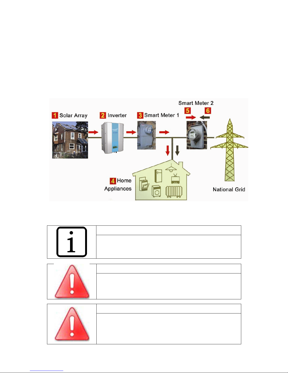
3.1 The application in PV system
The grid-connected PV system consists of PV arrays,photovoltaic combiner
box.photovoltaic grid-connected inverter,metering devices and utility grid(see figure
3-1)
Figure 3-1 PV Grid-connected system
Note!
Need permission from the local power department to allow
connected grid and invited the professional electrician to install
it.
Warning!
Make sure the individual PV modules are with the same
specification in the PV array.
Warning!
Make sure the PV array to be negative grounding.
9
3.2 The Features
•Using high frequency technique and advanced IGB,the system efficiency is
enhanced.
•High conversion efficiency
•Advanced technology for maximum power point tracking(MPPT)
•>99% MPPT efficiency
•Wide input voltage range
•Efficient design of high-frequency isolation transformer
•High efficiency at wide power range
•Advanced anti-islanding technology
•High reliability due to complete protection function
•Easy operation,installation and maintenance
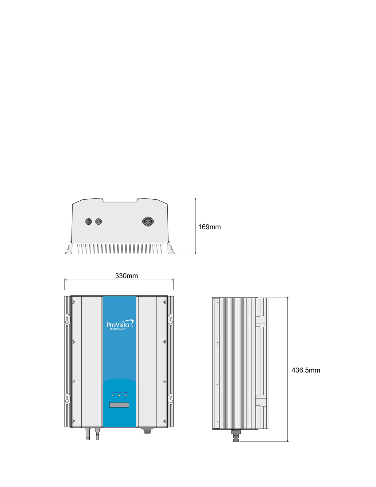
3.3 Dimensions of the GTW1500 HF
10
4.Operation
The gird feed process begins in the morning if sufficient insolation is available, and,
therefore, if a certain minimum voltage is present in the inverter.
If, as nightfall approaches, the voltage drops below the minimum voltage value, gird fee
mode ends and the inverter switches off.
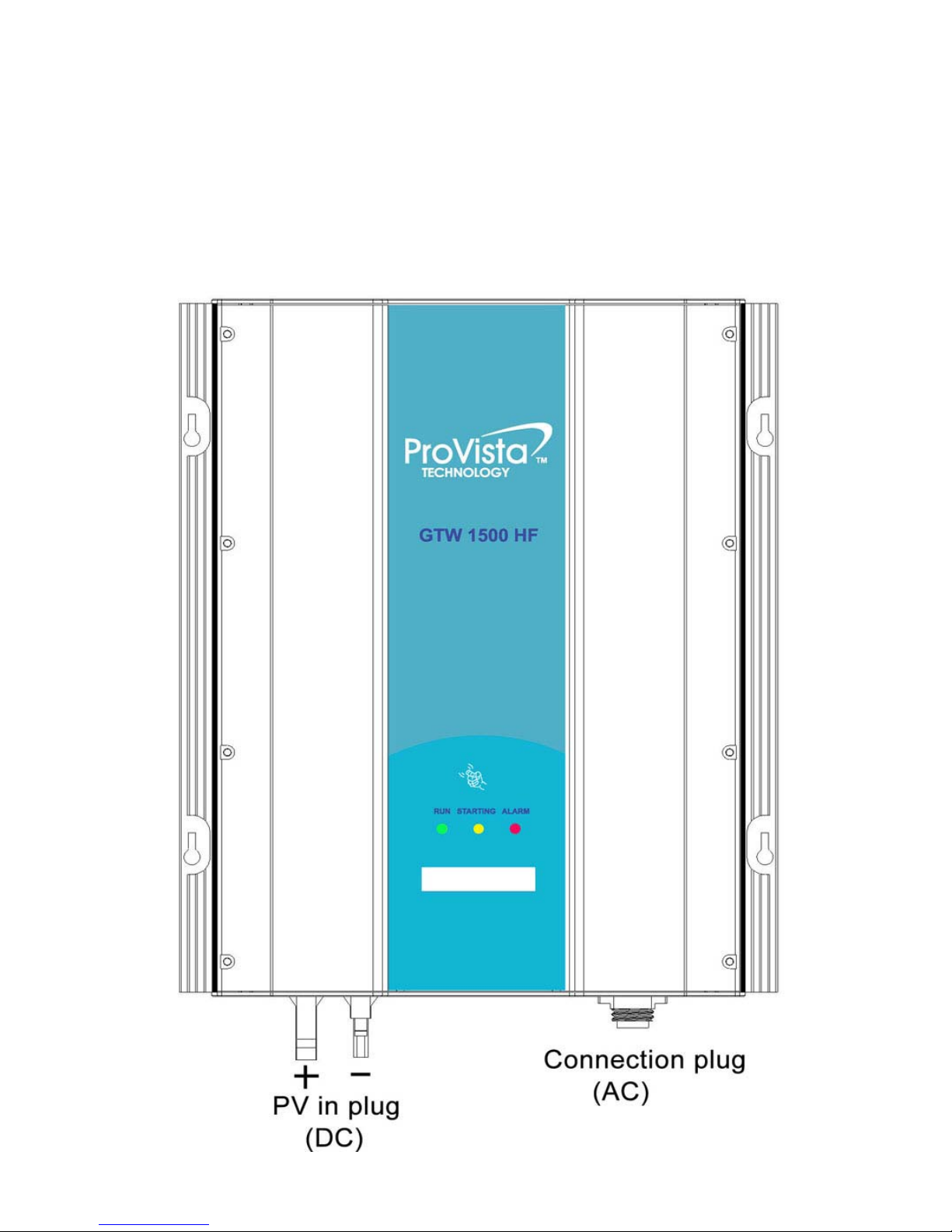
4.1 Overview
11
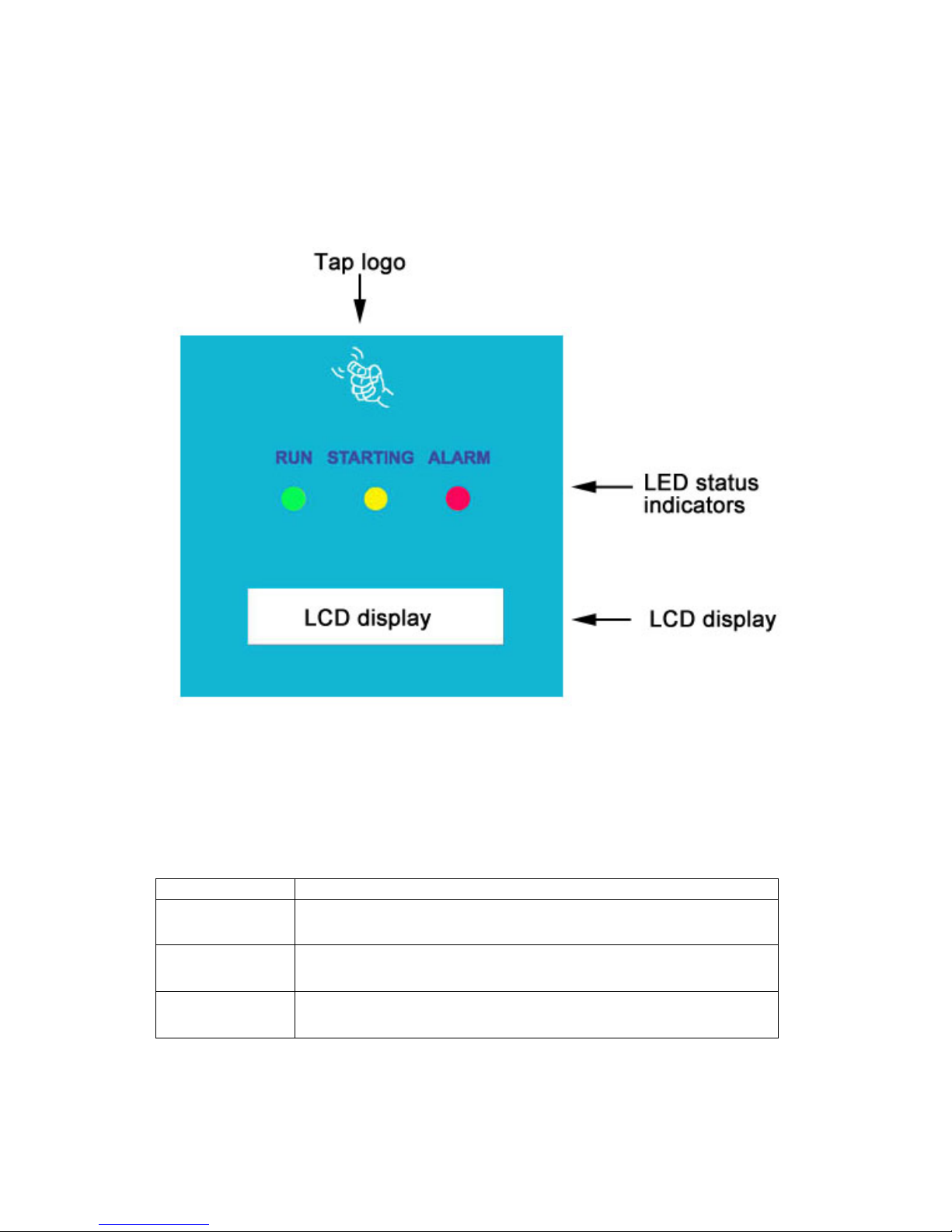
4.2 Control panel
4.2.1 Display
The control panel is composed of the LCD display and 3 LED lights.The system can be
easily monitored.
4.2.2 LED indicators
Provista inverter with high intelligence,start and stop working each day automatically
without human control.There are 3 LED lights in the Control panel. We can know the
working state of inverter from these lights. The states of each LED light signals are in
the following table.
LED Color Status
Green “RUN” means normal operation
Yellow “STARTING” means start operation
Red “ALARM” means over-voltage, or under-voltage, or over-current,
or islanding
4.2.3 LCD backlight control:
When supply power, the LCD backlight lights. When initialization is completed, and the inverter
worked normally about 8 seconds, the backlight will go out. Then knock the panel, backlight lights.
If there is no knock signal for 8 seconds, the backlight will go out.
12
4.3 LCD display
4.3.1 Initialization interface
After system power supply, the three lights light at the same time, LCD initial screen display as Menu
1, it also shows another, if the program is updated.
Menu 1: PV_Grid Inverter (Yellow LED display)
ProVista
PV_Grid Inverter
After the system progress bar shows, the fault indicator eliminate. Then LCD display device version
information, LCD screen display as Menu 2, it also shows another, if the progress is updated.
Menu 2:Version(Yellow LED display)
Display Ver 1.10
Control Ver 1.10
Next, it will go into the Checking, LCD screen display as Menu 3, it also shows another, if the progress
is updated. Menu 3: Checking(Yellow LED display)
Checking
>>>>>>>>>>>>>>>>
4.3.2 Operating parameters display interface
About 2 seconds after version display interface, LCD displays the following five display
interface(Menu 4 to Menu 8) in turn. Each interface shows about 10 seconds.
Menu 4:Grid Current, Voltage, Frequency(Green LED display)
Grid: 4.56A
49.9HZ 230V
Menu 5:PVArray Current, Voltage(Green LED display)
PVin: 3.61A
310V
Menu 6: Input and Output Power(Green LED display)
Pin: 1119W
Pout: 1048W
Menu 7:Today Power and Total Power accumulated (Green LED display)
E-day: 3.81kwh
E-tot: 136.11kwh
Menu 8:Temperature and operating mode (Green LED display)
Temp: 18 Deg C
Mode MPPT

13
4.3.3 Fault-screen display interface
When a fault occurs, whatever the current LCD display is, it will pop-up fault screen tips until the fault
disappears, such as fault indicator lights, LCD screen displays as the following 7 display interface (Menu 9
to Menu 15). it also shows another, if the progress is updated
.
Menu 9:(RED LED display)
PVArray Voltage
Out of range
Menu 10:(RED LED display)
DC Component
Out of range
Menu 11:(RED LED display)
Grid Frequency
Out of range
Menu 12:(RED LED display)
Output Current
Out of range
Menu 13:(RED LED display)
---NOTICE---
<Islanding>
Menu 14:(RED LED display)
Temperature
Out of range
Menu 15:(RED LED display)
---NOTICE---
<NO POWER>
14
4.3.4 Auto test display interface
When entering the auto test mode,display interface:
Start
" ProVista "
"PV_Grid Inverter "
" Display Ver 1.10 "
" Control Ver 1.10 "
Please beat the panel
" Auto Test "
" ? "
Please beat the panel
" Auto Test "
" Start "
" Grid Volt-High "
" Protection 261V "
" Grid Volt-High "
" Protec Max 262V "
" Grid Volt-High "
" Protection 230V "
" Grid Volt-High "
" Prote Pass 230V "
" Grid Volt-High "
" Prote Time 40ms "
" Grid Volt-High "
" Protection 262V "

15
" Grid Volt-Low "
" Prote Time 40ms "
" Grid Freq-High "
" Prote Max51.0Hz "
" Grid Freq-High "
" Protection 51.0Hz "
" Grid Freq-High "
" Protection 50.9Hz "
" Grid Volt-Low "
" Protection 187V "
" Grid Volt-Low "
" Protection 188V "
" Grid Volt-Low "
" Protection 230V "
" Grid Volt-Low "
" Prote Pass 230V "
" Grid Volt-Low "
" Protec Min 187V "
" Grid Freq-High "
"Prote Pass 50.1Hz "
" Grid Freq-High "
" Protection 50.1Hz "
16
WORKING
" Grid Freq-Low "
" Prote Pass 50.1Hz "
" Grid Freq-Low "
" Prote Time 40ms "
" TestFinish "
" "
" Grid Freq-Low "
" Prote Min49.0Hz "
" Grid Freq-Low "
" Protection 49.0Hz "
" Grid Freq-Low "
" Protection 49.1Hz "
" Grid Freq-Low "
" Protection 50.1Hz "
" Grid Freq-High "
" Prote Time 40ms "
17
5.Installation
Please read the installation instruction carefully before installation. Pay attention to the safety
of the fitting instruction.
5.1 Installation requirements
Please check that all of the conditions listed below are met before installing and setting up
the GTW1500 HF
5.1.1 Ambient conditions
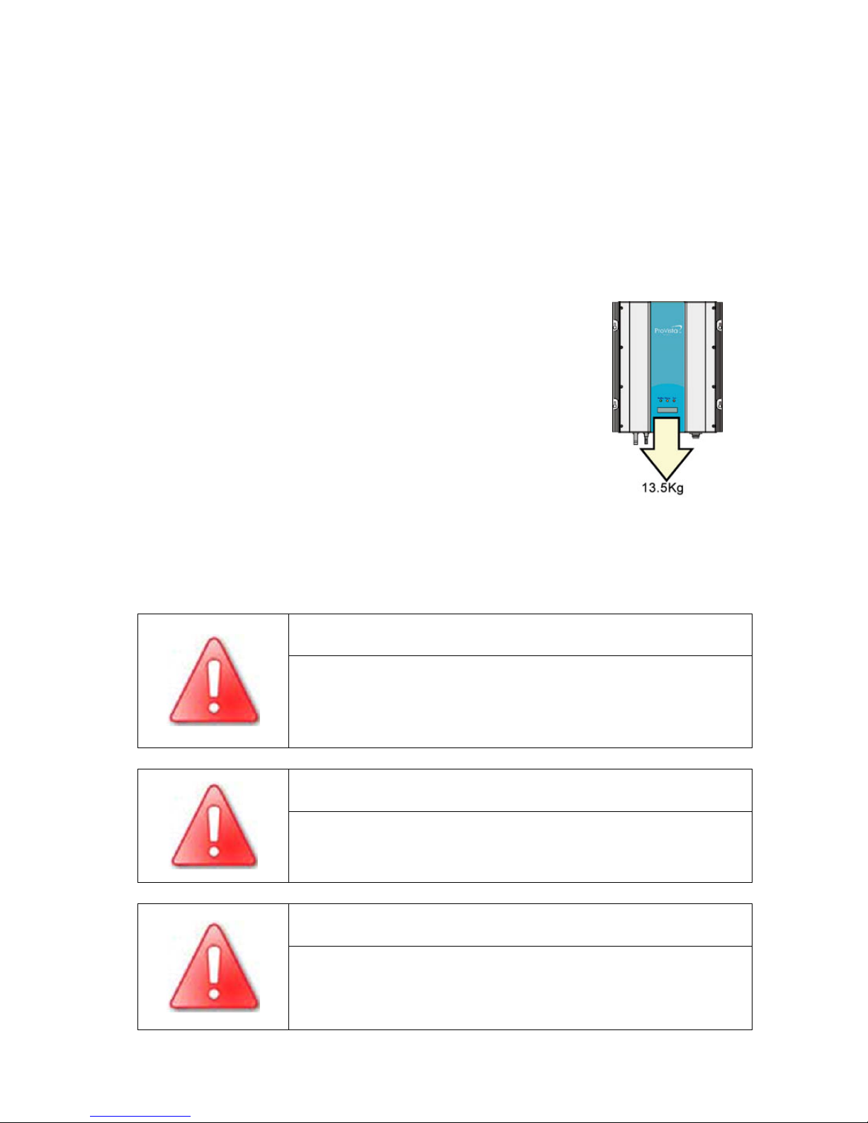
The ambient temperature must be within -25 °C to +50°C.
The GTW1500 HF weighs 13.5 kg. Please take this weight into
account when choosing the installation site and method of fastening
the wall mounting bracket.
In domestic installations, the unit should not be mounted on
plasterboard walls or similar as otherwise audible vibrations are likely
to result.
The GTW1500 HF should be installed in a place where it is not
exposed to direct sunlight. An increased ambient temperature can
reduce the yield of the PV system.
Provide better ventilation for GTW1500 HF to ensure that heat is dissipated adequately.
According to EMC and noise level, the installation location is as far as possible away from
the living area.
Warning!
Unintentionally pulling out the DC plug connectors under load can
damage the plug and result in a serious injury! Install the GTW1500
HF in such a way that it is not possible (e.g. for children) to unplug
the DC plug connector accidentally.
Warning!
Individual components in the GTW1500 HF an reach a temperature
of more than 50 °C
Warning!
Do not install the GTW1500 HF on flammable construction
materials, in areas where highly inflammable materials are stored or
in potentially explosive environments!
18
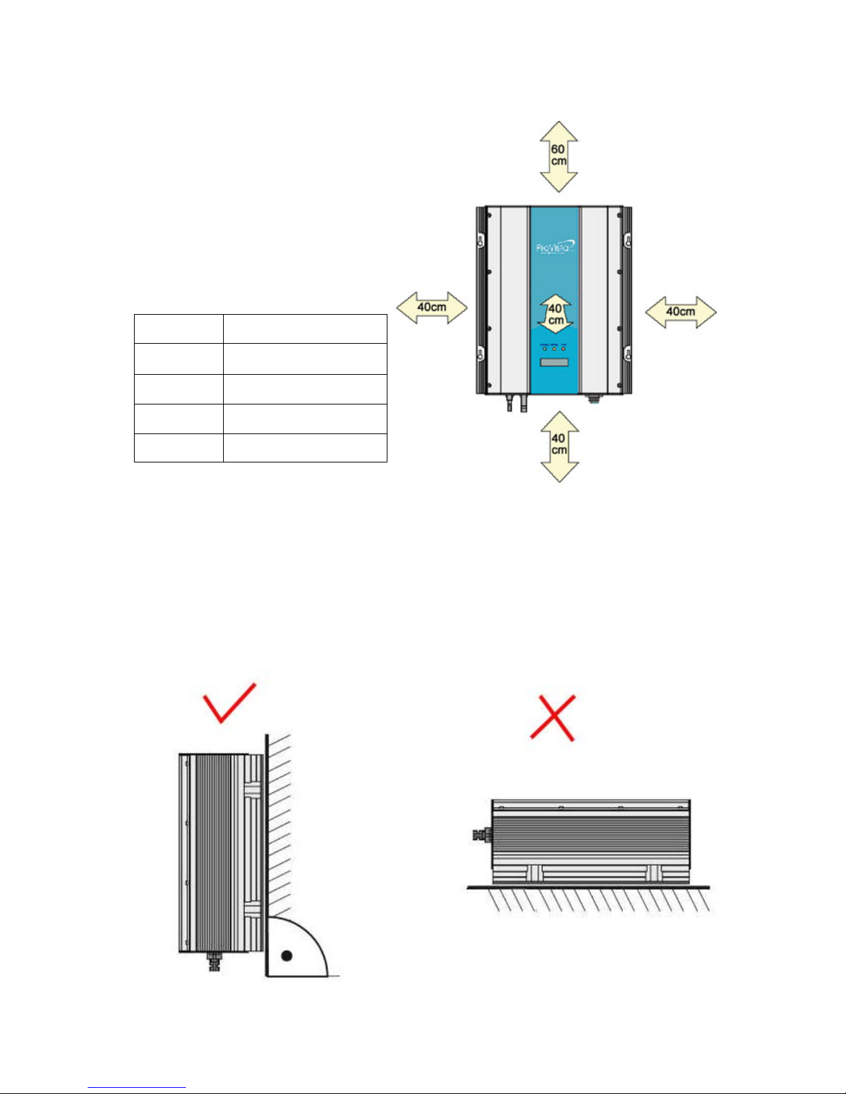
When choosing the installation site, ensure there is enough space for heat to dissipate. Under
normal conditions, the following guidelines should be applied for the space to be kept clear
around the GTW1500 HF:
Minimum clearance
Direction Minimum clearance
above 60cm
below 40cm
sides 40cm
In front 40cn
5.2 Position
The GTW1500 HF is designed to be mounted on a vertical wall. For an optimum energy
yield and the most convenient operation, vertical installation at eye-level is preferable. In
case it is absolutely necessary to tilt the GTW1500 HF to the back the maximum angle is
10 °. If installing the unit outdoors, make sure that it is not slanted forwards.
It is not recommended to install the GTW1500 HF lying on the back side with the lid facing
upwards.

19
5.3 Installation
1. Drill four holes for the screws at the selected installation position.The space between every
every holes is shown as below photo.
Keep drilling vertical to the wall, and don’t shake the drill to avoid holes tilting.
2. Please fix the wall bracket on the wall with the explosion screws. Mount the
GTW1500-HF on the wall bracket.

20
6.Electrical connection
This chapter describes electrical connection between the GTW1500 inverter,solar arrays and
the power grid. Before the connection,please carefully read the following steps.
6.1 Wire specifications
Before installation, please reference the wires recommended sizes as below table.
Wire Requirements(AWG)
PV DC+ wire 12AWG
PV DC- wire 12AWG
GND wire 12AWG
Grid L wire 12AWG
Grid N wire 12AWG
6.2 AC connection steps
Warning!
Before you connect the mains cable to the AC connection socket,
make sure that no voltage is present at the cable.
1. AC output socket as below.
2. AC socket parts included as below
Table of contents
Other ProVista Technology Inverter manuals

Popular Inverter manuals by other brands

DuroStar
DuroStar DS7000Q owner's manual

TBB
TBB Energier Pro Series user manual

Centurion
Centurion 04791-0 Owner's manual and installation instructions

SolarEdge
SolarEdge StorEdge SE5K-RWS installation guide

Kyocera
Kyocera KC Series installation manual

Generac Power Systems
Generac Power Systems Guardian Elite 005259-0 owner's manual


