Status at: August 2017 ESE 406 - 606 (D)HG-GT (ES) Duplex 7
Figure 2-1: Signs on the generator.....................................20
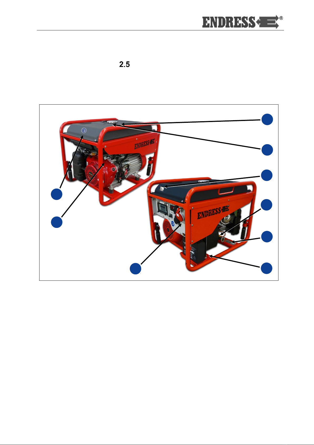
Figure 3-1: Views of the generator......................................29
Figure 3-2: Components on the operating and exhaust side
....................................................................................30
Figure 3-3: Engine and maintenance side components......31
Figure 3-4: Control panel components * .............................32
Figure 4-1: Attachment of the carrying straps.....................36
Figure 4-2: Hand start operating controls............................40
Figure 4-3: Hand choke position.........................................40
Figure 4-4: Electrical start...................................................41
Figure 4-5: Connect up to consumers.................................45
Figure 4-6: Feed plug in the scope of delivery....................47
Figure 4-7: Equipment specification example Main
distribution TN system / TT system..............................49
Figure 4-8: Idle down rocker switch....................................50
Figure 4-9: Multi-functional display.....................................51
Figure 5-1: FI protection switch ..........................................55
Figure 5-2: Insulation monitoring........................................56
Figure 5-3: Remote start device .........................................58
Figure 5-4: Cable remote control........................................59
Figure 6-1: Oil dipstickand oil drain plug.............................62
Figure 6-2: Replacing the battery .......................................65
Figure 9-1: Replacement parts for the frame / engine /
generator.....................................................................72
Figure 9-2: Replacement parts Electrical junction box........74
List of tables
Table 2.1: Danger zones and work areas on the generator 19
Table 2.2: Signs on the generator.......................................21
Table 5.1: FI protection switch test.....................................55
Table 5.2: Insulation monitoring plus switching off..............56
Table 5.3: Insulation monitoring whilst running without
switching off ................................................................57
Table 6.1: Generator maintenance plan .............................61
Table 7.1: Troubleshooting during generator operation ......67
Table 8.1: Ambient conditions for the generator .................70
Table 8.2: Generator power reduction dependent on ambient
conditions....................................................................70
Table 8.3: Maximum line length of the distribution network as
a function of the cable cross-section............................70
Table 9.1: Replacement parts for the frame / engine /
generator.....................................................................73
Table 9.2: Replacement parts Electrical junction box .........74