Frecon FR200H User manual

FR200H Special Purpose Inverters for Multi-pumps Constant Pressure Water Supply
- 1 -
Preface
FR200H series is a enhanced type during all FRECON inverters group, special design for
HVAC, air conditioner and water-supply industry, use for fan, pumps and other loads, support 2
modes water supply of fixed variable-frequency pump and cycle variable-frequency pumps, flexible
control logic of add/reduce pumps, dormancy/awaken based on pressure, timing rotate control and
other special functions.
When debugging the product, please refer to debugging guide in the user manual. Product
maintenance please refers to FR200 user manual.
IMPORTANT NOTES
◆To illustrate the details of the products,pictures in this manual based on products with outer
casing or safety cover being removed.When using this product, please be sure to well install
outer casing or covering by the rules, and operating in accordance with the manual contents.
◆The illustrations this manual for illustration only and may vary with different products you have
ordered.
◆The company is committed to continuous improvement of products, product features will
continue to upgrade, and the information provided is subject to change without notice.
◆If you are using have questions; please contact our regional agents or our customer service
center. Customer Service Tel 0755 -33067999.
◆The company's other products please visit our website: http://www.frecon.com.cn

FR200H Special Purpose Inverters for Multi-pumps Constant Pressure Water Supply
- 2 -
Contents
Preface ........................................................................................................................................- 1 -
Contents ......................................................................................................................................- 2 -
Chapter 1 Product Information...................................................................................................- 3 -
1.1 Nameplate information .......................................................................................................- 3 -
1.2 Information of FR200H Product Model................................................................................- 4 -
1.3 Terminal Configuration........................................................................................................- 4 -
1.4 Configuration, Mounting Dimensions and Weight ................................................................- 8 -
Chapter 2 Debugging Guide .....................................................................................................- 10 -
Chapter 3 List of Parameters.................................................................................................... - 11 -
3.1 Standard Function Parameters ......................................................................................... - 11 -
Chapter 4 Maintenance and troubleshooting ..........................................................................- 27 -

FR200H Special Purpose Inverters for Multi-pumps Constant Pressure Water Supply
- 3 -
Chapter 1 Product Information
1.1 Nameplate information
Fig.1-1 Nameplate information
Model Explanation
Model show on product nameplate contains information below
FR200 H-4T-7.5G/011P B
Product series code:
FR200H
Input voltage:
2: 220V(-15%~+30%)
4: 380V(-15%~+30%)
Input voltage phases:
S:Single-phase
T:Three-phase
Industry-specific series
code H: special use for
multi-pumps constant
pressure water supply
Brake unit:
None: No Braking Unit
B: Built-in brake unit(30kW
following built,37 ~ 75kW optional
built,No built above 90kW)
Adaptable Motor (kW)And Type of
Motor:7.5G:7.5kW(General type)
011P:11kW(Fan pump type)
Figure 1-2 Product Model Number Naming Rule

FR200H Special Purpose Inverters for Multi-pumps Constant Pressure Water Supply
- 4 -
1.2 Information of FR200H Product Model
Table 1-1FR200HProduct model and technical data
Model No.
Power
capacity
KVA
Rated
Input current
A
Rated output
current
A
Applicable motor
kW HP
3-Phase: 380V,50/60Hz Range: -15%~+30%
FR200H-4T-0.7G/1.5PB
1.5
3.4
2.5
0.75
1
FR200H-4T-1.5G/2.2PB
3
5.0
4.2
1.5
2
FR200H-4T-2.2GB
4
5.8
5.5
2.2
3
FR200H-4T-4.0G/5.5PB
6
11
9.5
3.7、4
5
FR200H-4T-5.5G/7.5PB
8.9
14.6
13
5.5
7.5
FR200H-4T-7.5G/011PB
11
20.5
17
7.5
10
FR200H-4T-011G/015PB
17
26
25
11
15
FR200H-4T-015G/018PB
21
35
32
15
20
FR200H-4T-018G/022PB
24
38.5
37
18.5
25
FR200H-4T-022G/030PB
30
46.5
45
22
30
FR200H-4T-030G/037PB
40
62
60
30
40
FR200H-4T-037G/045P
57
76
75
37
50
FR200H-4T-037G/045PB
FR200H-4T-045G/055P
69
92
91
45
60
FR200H-4T-045G/055PB
FR200H-4T-055G/075P
85
113
112
55
70
FR200H-4T-055G/075PB
FR200H-4T-075G/090P
114
157
150
75
100
FR200H-4T-075G/090PB
FR200H-4T-090G/110P
134
160*
176
90
125
FR200H-4T-110G/132P
160
190*
210
110
150
FR200H-4T-132G/160P
192
232*
253
132
175
FR200H-4T-160G/185P
231
282*
304
160
210
FR200H-4T-185G/200P
240
326*
350
185
250
FR200H-4T-200G/220P
250
352*
377
200
260
FR200H-4T-220G/250P
280
385*
426
220
300
FR200H-4T-250G/280P
355
437*
470
250
330
FR200H-4T-280G/315P
396
491*
520
280
370
FR200H-4T-315G/355P
445
580*
600
315
420
FR200H-4T-355G/400P
500
624*
650
355
470
FR200H-4T-400G/450P
565
690*
725
400
530
FR200H-4T-450G/500P
623
765*
800
450
600
1.3 Terminal Configuration
1.3.1 Main Circuit Terminals
a: 1.5~2.2kWMain Circuit Terminals
(+) (-) RSTUV
POWER
Control circuit
terminals
Main circuit
terminals
Upload and
download interfaces
Fig.1-3 1.5~2.2kW Schematic of main circuit terminals

FR200H Special Purpose Inverters for Multi-pumps Constant Pressure Water Supply
- 5 -
b:4~18.5kW Main Circuit Terminals
Control circuit
terminals
Main circuit
terminals
Upload and
download interfaces
PB (+) (-)
RFI
Fig.1-4 4.0~18.5kW Schematic of main circuit terminals
c: 22~30kW Main Circuit Terminals
Solution 1:
Fig.1-5 22~37kW Main Circuit Terminals(Solution 1)Schematic
Solution 2:
Fig.1-6 22~37kW Main Circuit Terminals(Solution 2)Schematic
d: 45~90kW Main Circuit Terminals
Fig.1-7 45~90kW Main Circuit TerminalsSchematic

FR200H Special Purpose Inverters for Multi-pumps Constant Pressure Water Supply
- 6 -
e: 110~315kW Main Circuit TerminalsSchematic
Fig.1-8 110~315kW Main Circuit TerminalsSchematic
f:355-400kW Main Circuit Terminals
Fig.1-9 355~400kW Main Circuit TerminalsSchematic
Table 1-2 main circuit terminal functions
Terminal marks
Functions
R/L1、S/L2、T/L3
AC power input terminals for connecting to 3-phase AC380V
power supply.
U/T1、V/T2、W/T3
AC output terminals of inverter for connecting to 3-phase
induction motor.
(+)、(-)
Positive and negative terminals of internal DC bus.
B
Connecting terminals of braking resistor. One end connected
to + and the other to B.
Grounding terminal
2.3.2 Control circuit terminals
Fig. 1-10 control circuit terminalsschematic
DI1
+24V
DI2
PLC
DI3
COM
DI4
DI5
COM
DI6
Y1 Y2
+10V R1A R1B R1C
R2A R2B R2C
AO1
AI1
GND
AI2
485+
AI3
485-
PE
DI7/HI
AO2
GND

FR200H Special Purpose Inverters for Multi-pumps Constant Pressure Water Supply
- 7 -
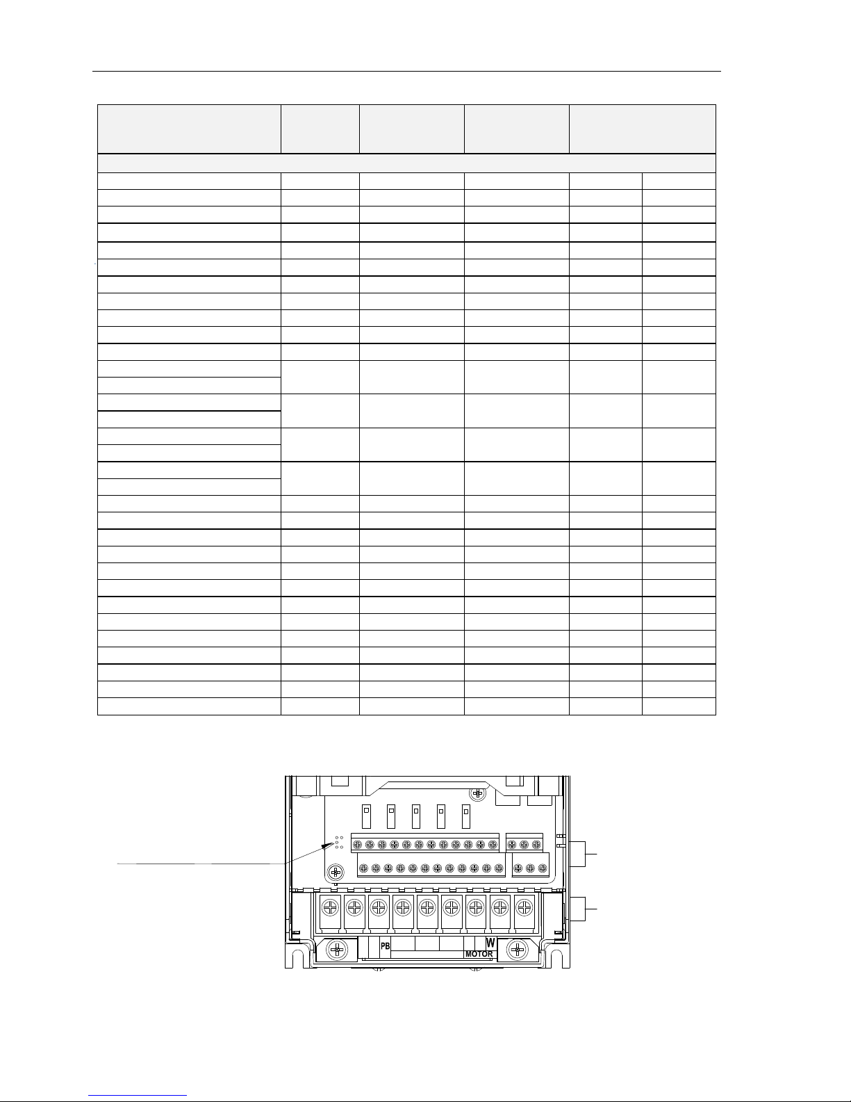
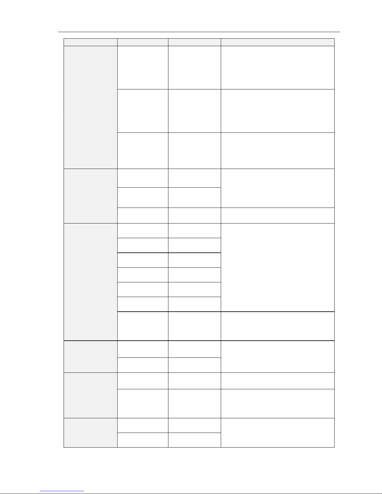
Table 1-3 FR200H Description of control circuit terminals
Type
Terminal
Name
Function Description
Power supply
+10V-GND
External +10 V
power supply
Provide +10 V power supply to
external unit.
Generally, it provides power supply to
externalpotentiometer with resistance
range of 1–5 kΩ.
Maximum output current: 10 mA
+24V-COM
External +24V
power
supply Applying
to Overvoltage
Category II
circuit
Provide +24 V power supply to
external unit.
Generally, it provides power supply to
DI/Do terminals and external sensors.
Maximum output current: 200 mA
PLC
Input terminal
of
external power
supply
Connect to +24 V by default.
When DI1-DI7 need to be driven by
externalsignal, PLC needs to be
connected to externalpower supply
and be disconnected from +24 V.
Analog input
AI1-GND
Analog input 1
Input voltage range: DC 0~10V/0~
20mA,decided by toggle switches
AI1、AI2 on the control board
Impedance: 250 kΩ (voltage input),
250 Ω (current input)
AI2-GND
Analog input 2
AI3-GND
Analog input 3
Input Voltage Range: DC -10~+10V
Input impedance: 250kΩ
Switch input
DI1- COM
Switch input
terminals 1
Maximum input frequency: 200Hz
Impedance: 2.4kΩ
Voltage range for level input: 9V~
30V
DI2- COM
Switch input
terminals 2
DI3- COM
Switch input
terminals 3
DI4- COM
Switch input
terminals 4
DI5- COM
Switch input
terminals 5
DI6- COM
Switch input
terminals 6
DI7/HI-COM
Switch input
terminals 7 OR
High-speed
pulse input
Besides features of DI1–DI6, it can be
used for high-speed pulse input.
Maximum input frequency: 100 kHz
Analog
output
AO1-GND
Analog output
terminal 1
Output voltage range: DC 0~10V/0~
20mA,decided by toggle switches
AO1、AO2 on the control board
Impedance requirements≥10kΩ
AO2-GND
Analog output
terminal 2
Switch output
Y1-COM
Open collector
output 1
Voltage range: 0~24V
Current range: 0~50mA
Y2/HO-COM
Open collector
output 2 OR
High-speed
pulse output
Besides features of Y1, it can be used
forHigh-speed pulse output channels.
The maximum output frequency:
100kHz
Relay output
R1A-R1C
Normally open
terminal
Contact driving capacity:
AC250V,3A,COSØ=0.4.
DC 30V,1A
R1B-R1C
Normally
closedterminal

FR200H Special Purpose Inverters for Multi-pumps Constant Pressure Water Supply
- 8 -
R2A-R2C
Normally open
terminal
R2B-R2C
Normally
closedterminal
485
Communication
485+-485-
485
Communication
Terminals
Rate:
4800/9600/19200/38400/57600/
115200bps
Termination resistor is set by the
toggle switch on the control panel
RS485
GND
485
Communication
shielded
ground
Shield
PE
Shield Ground
Ground terminal for shield
Auxiliary
Interface
External
operation
panel interface
Use standard network cable
Maximum cable distance: 50m
UP/DOWNLOAD
Parameter
copy interface
1.4 Configuration, Mounting Dimensions and Weight
a:1.5~18.5kW Dimensions and wall mounting dimensions
Fig. 1-11 1.5~18.5kW Wall installation diagram
b: 22~400kW Dimensions and wall mounting dimensions
Fig.1-12 22~160kW Wall installation diagram (1) Fig. 1-13185~400kW Wall installation diagram (2)
W1
H1
H
W
D
4Xd
W1
W
H1
H
D
4xd
H
WD
H1
dW1 W1

FR200H Special Purpose Inverters for Multi-pumps Constant Pressure Water Supply
- 9 -
Table 1-4 Configuration, mounting dimensions and weight
Model NO.
External and installation dimensions(mm)
Weight
(Kg)
W
W1
H
H1
D
Mounting
Hole
Diameter
3-Phase: 380V,50/60Hz Range: -15%~+30%
FR200H-4T-0.7G/1.5PB
117
107
187
177
160
4.5
1.9
FR200H-4T-1.5G/2.2PB
FR200H-4T-2.2GB
FR200H-4T-4.0G/5.5PB
146
131
249
236
177
5.5
3.2
FR200H-4T-5.5G/7.5PB
FR200H-4T-7.5G/011PB
FR200H-4T-011G/015PB
198
183
300
287
185
5.5
5.4
FR200H-4T-015G/018PB
FR200H-4T-018G/022PB
255
176
459
443
220
7
15.5
FR200H-4T-022G/030PB
FR200H-4T-030G/037PB
FR200H-4T-037G/045P
270
130
590
572
260
7
27.5
FR200H-4T-045G/055P
FR200H-4T-055G/075P
357
230
590
572
260
7
37
FR200H-4T-075G/090P
FR200H-4T-090G/110P
430
320
830
802
293
12
77.7
FR200H-4T-110G/132P
FR200H-4T-132G/160P
FR200H-4T-160G/185P
500
180
1107
1078
328
14
138.5
FR200H-4T-185G/200P
FR200H-4T-200G/220P
FR200H-4T-220G/250P
660
230
1160
1130
340
14
190
FR200H-4T-250G/280P
FR200H-4T-280G/315P
FR200H-4T-315G/355P
810
300
1140*
1110
400
14
196
FR200H-4T-355G/400P
FR200H-4T-400G/450P
* Note: 1. 110~315kw optional base height is 263mm.
2. 355~400kw dc reactor can be installed in a trench or cabinet independently, if the vertical installation,
need to purchase base (dc reactor can be installed in the base), base height is 400 mm.

FR200H Special Purpose Inverters for Multi-pumps Constant Pressure Water Supply
- 10 -
Chapter 2 Debugging Guide
FR200H series special purpose inverter for multi-pumps constant pressure water supply specially
developed for constant pressure water supply industry, featured with 2 modes below:
Mode 1: fixed variable frequency control mode wirings:
DI1
DI2
DI3
DI4
DI6
COM
FR200H
DI5
Q3
Q4
Default Signal
Q2
10V
AI1
AI2
GND
Given
Feedback
FWD
REV
Q5 DI7
R1A
R1C
R2A
R2C
KA1
KA2
Y1
Y2
24V
M1
M2
M3
M4
M5
L1
L2
L3
220V
KM2 KM3 KM4 KM5
R1A
R1C
R2A
R2C
KA1 KA2
R
S
T
U
V
W
Inside the dotted line is power-
frequency pumps, can be added on
customers’requirements up to 4 pcs
Fig. 2-1 Fixed Pumps Mode Wirings
Mode 2: two variable frequency pumps cycle control mode wirings:
DI1
DI2
DI3
DI4
DI6
COM
FR200H
DI5
Q3
Q4
Default Value
Q2
10V
AI1
AI2
GND
Given
Feedback
FWD
REV
Q5 DI7
R1A
R1C
R2A
R2C
KA1
KA2
Y1
Y2
24V
M1
L1
L2
L3
M2
KM1
KM2
KM3
KM4
U
V
W
R
S
T
220V
KM1 KM2 KM3 KM4
R1A
R1C
R2A
R2C
KA1 KA2
Fig. 2-2 two variable frequency cycle mode wirings

FR200H Special Purpose Inverters for Multi-pumps Constant Pressure Water Supply
- 11 -
Chapter 3 List of Parameters
3.1 Standard Function Parameters
Table 3-1 Standard Function Parameters
Param.
Parameter Name
Instructions
Default
Attr
Group F00: System Parameters
F00.00
User Password
0~65535
0
×
F00.01
Display of Parameters
0: Display all parameters
0
×
1: Only display F00.00, F00.01
and user-defined parameters
F17.00~F17.29
2: Only display F00.00, F00.01,
and the parameters different with
factory default
F00.03
G/P type display
0: G type (constant torque load)
1
×
1: P type (variable torque load
e.g. fan and pump)
F00.04
Parameter Initialization
0: Invalid
0
×
1: Restore all parameters to
factory default (excluding motor
parameters)
2: Clear fault record
3: Restore user backup
parameters
4: Back up user parameters
5: Restore factory default(include
motor parameters)
6: Clear power dissipation
Group F01: Frequency Command
F01.01
Master Frequency
Command Source
0: Master digital setting (F01.02)
6
×
1: keypad potentiometer
2: Analog input AI1
3: Communication
4: Multi-reference
5: PLC
6: Process PID output
7: DI7/HI pulse input
8: Analog input AI2
9: Analog input AI3
F01.08
Maximum frequency
20.00~600.00Hz
50.00Hz
×
F01.09
Upper limit frequency
Fdown~Fmax
50.00Hz
×
F01.10
Lower limit frequency
0.00~Fu
0.00Hz
×
F01.11
Operation when
command frequency
lower than lower limit
frequency
0: Run at lower limit frequency
0
×
1: Run at 0 Hz would be
activated after the time delay set
by F01.12
F01.12
Lower limit frequency
running time
0.0~6000.0s
60.0s
×
Group F02: Start/Stop Control
F02.00
Run command
0: Keypad control (LED off)
1
×
1: Terminal control (LED on)
2: Communication control (LED
blinking)
F02.12
Stop mode
0: Ramp to stop
0

FR200H Special Purpose Inverters for Multi-pumps Constant Pressure Water Supply
- 12 -
1: Coast to stop
F02.20
0Hz output selection
0:No-voltage output
0
×
1:Voltage output
Group F03: Accel/Decel Parameters
F03.00
Accel time 1
0.0~6000.0s
15s
△
F03.01
Decel time 1
0.0~6000.0s
15s
△
Group F04 Digital Input
F04.00
Function of terminal DI1
00: No function
01: Running forward (FWD)
02: Running reverse (REV)
03: Three-wire running control
04: JOG forward (FJOG)
05: JOG reverse (RJOG)
06: Coast to stop
07: Fault reset (RESET)
08: Running pause
09: External fault input
10: Terminal Up
11: Terminal DOWN
12: UP/DOWN (including ∧/∨
key) adjustment clear
13: Multi-step frequency terminal
1
14: Multi-step frequency terminal
2
15: Multi-step frequency terminal
3
16: Multi-step frequency terminal
4
17: Accel/Decel time determinant
1
18: Accel/Decel time determinant
2
19: Accel/Decel disabled(ramp
stop not inclusive)
20: Given frequency switching as
the auxiliary frequency source
21: PLC status reset
22: Simple PLC paused
23: ID paused
24: PID adjustment direction
25: PID integration paused
26: PID parameter switch
27: Swing frequency
pause(output the
currentfrequency)
28: Swing frequency reset(output
the central frequency)
29: Run command switched to
keypad control
30: Run command switched to
terminal control
31: Run command switched to
communication control
32: Count input
33: Count clear
34: Length pulse input
35: Length clear
1
×
F04.01
Function of terminal DI2
2
×
F04.02
Function of terminal DI3
7
×
F04.03
Function of terminal DI4
13
×
F04.04
Function of terminal DI5
0
×
F04.05
Function of terminal DI6
0
×
F04.06
Function of terminal DI7
0
×

FR200H Special Purpose Inverters for Multi-pumps Constant Pressure Water Supply
- 13 -
36: DC brake input command at
stop
37:Speed/Torque control switch
38: Disable reverse
39: Disable forward
50: Special purpose inverter
enable
51: No.1 pump status
52: No.2 pump status
53: No.3 pump status
54: No.4 pump status
55: No.5 pump status
F04.13
Terminal DI1~DI5
positive/negative logic
DI5、DI4、DI3、DI2、DI1
00000
0: Positive logic(Terminals are on
at 0V/off at 24V)
1: Negative Logic (Terminals are
off at 0V/on at 24V)
F04.14
Terminal DI6~AI3
positive/negative logic
AI3、AI2、AI1、DI7、DI6
00000
0: Positive logic
1: Negative Logic
Group F05 Digital Output
F05.00
Y1 output function
00: No output
01: Drive is running
02: Fault output
03: Frequency-level detection
(FDT1)
04: Frequency-level detection
(FDT2)
05: Drive in 0Hz running 1 (no
output at stop)
06: Drive in 0Hz running 2(output
at stop)
07: Upper limit frequency
attained
08: Lower limit frequency
attained
09: Frequency attained
10: Inverter is ready to work
11: Drive (motor) overloaded
alarm
12: Inverter overheat warning
13: Current running time attained
14: Accumulative power-on time
attained
15: Consecutive running time
attained
16: PLC cycle completed
17: Set count value attained
18: Designated count value
attained
19: Length attained
20: Under-load warning
21: Brake output
22: DI1
23: DI2
30: No.1 pump power-frequency
control terminal
31: No.2 pump power-frequency
1
×
F05.01
Y2 output function
3
×
F05.02
Relay 1 output function
2
×
F05.03
Relay 2 output function
11
×

FR200H Special Purpose Inverters for Multi-pumps Constant Pressure Water Supply
- 14 -
control terminal
32: No.3 pump power-frequency
control terminal
33: No.4 pump power-frequency
control terminal
34: No.5 pump power-frequency
control terminal
35: No.1 pump
variable-frequency control
terminal
36: No.2 pump
variable-frequency control
terminal
F05.08
Enabled state of digital
output
Unit: Y1
0000
0: Positive Logic
1: Negative Logic
Decade: Y2 (same as unit)
Hundreds place: Relay 1 output
(same asunit)
Thousands place: Relay 2 output
(same as unit)
Group F07 Analog and Pulse Output
F07.00
AO1 output function
00: No output
1
×
F07.01
AO2 output function
01: Output frequency
2
×
F07.02
Y2/HO output function
(when used as HO)
02: Command frequency
1
×
03: Output current (rated current)
04: Output voltage(rated voltage)
05: Output power
06: Bus voltage
07: +10V
08: keypad potentiometer
09: AI1
10: AI2
11: AI3
12: HI (100% to 10.00kHz)
13: Output torque (torque
absolute value)
Group F08 Parameters of Motor 1
F08.01
Rated power of motor 1
0.10~600.00kW
Model
defined
×
F08.02
Rated voltage of motor 1
60~660V
Model
defined
×
F08.03
Rated current of motor 1
0.1~1500.0A
Model
defined
×
F08.04
Rated frequency of
motor 1
20.00~Fmax
Model
defined
×
F08.05
Rated speed of motor 1
1~30000
Model
defined
×
F08.07
The rated power factor
of async motor 1
0.50~0.99
Model
defined
×
F08.08
Stator resistance R1 of
async motor 1
0.001~65.535Ω
Model
defined
×
F08.09
Rotor resistance R2 of
async motor 1
0.001~65.535Ω
Model
defined
×
F08.10
Leakage inductance L1
of async motor 1
0.001~65.535mH
Model
defined
×
F08.11
Mutual inductance L2 of
0.1~6553.5mH
Model
×

FR200H Special Purpose Inverters for Multi-pumps Constant Pressure Water Supply
- 15 -
asynchronous motor 1
defined
F08.12
No-load current of
async motor 1
0.1~1500.0A
Model
defined
×
F08.13
Field weakening coeff 1
of async motor 1
0.0~100.0
87%
×
F08.14
Field weakening coeff 2
of async motor 1
0.0~100.0
75%
×
F08.15
Field weakening coeff 3
of async motor 1
0.0~100.0
70%
×
F08.30
Autotuning of motor 1
0: No autotuning
0
×
1: Static autotuning of async
motor
2: Rotary autotuning of async
motor
Group F09 V/f Control Parameters of Motor 1
F09.00
V/f curve setting
00: LinearV/F
3
×
01: Multi-stage V/F
02: 1.2nd power V/F
03: 1.4th power V/F
04: 1.6th power V/F
05: 1.8th power V/F
06: 2.0nd power V/F
07: V/F complete separation
08: V/F half separation
09: 1.2 power inverse curve V/F
10: 1.4 power inverse curve V/F
11: 1.6 power inverse curve V/F
12: 1.8 power inverse curve V/F
13: 2.0 power inverse curve V/F
F09.01
Torque boost
0.0%–30.0% 0.0% (fixed
torque boost)
0.0%
△
F09.02
Cut-off frequency of
torque boost
0.00~Fmax
50.00Hz
△
F09.03
Multi-point V/F
frequency 1(F1)
0.00~F09.05
0.00Hz
△
F09.04
Multi-point V/F voltage 1
(V1)
0.0~100.0
0.0%
△
F09.05
Multi-point V/F
frequency 2(F2)
F09.03~F09.05
5.00Hz
△
F09.06
Multi-point V/F voltage 2
(V2)
0.0~100.0
14.0%
△
F09.07
Multi-point V/F
frequency 3(F3)
F09.05~F09.09
25.00Hz
△
F09.08
Multi-point V/F voltage 3
(V3)
0.0~100.0
50.0%
△
F09.09
Multi-point V/F
frequency 4(F4)
F09.07~rated motor frequency
50.00Hz
△
F09.10
Multi-point V/F voltage 4
(V4)
0.0~100.0 Ue=100.0%
100.0%
△
F09.11
V/F slip compensation
gain
0.0~300.0%
80.0%
△
F09.12
Stator voltagedrop
compensation gain
0.0~200.0%
100.0%
△
F09.13
Excitation boost gain
0.0~200.0%
100.0%
△
F09.14
Oscillation Suppression
0.0~300.0%
100.0%
△
Group F11 Protection Parameters

FR200H Special Purpose Inverters for Multi-pumps Constant Pressure Water Supply
- 16 -
F11.00
Current limit control
0: Current limit disabled
2
×
1: Current limit mode 1
2: Current limit mode 2
F11.01
Current limit
100.0~200.0%
150.0%
×
F11.02
Frequency decreasing
time(limit current in
constant speed
operation)
0.0~6000.0s
5.0s
△
F11.03
Current limit mode 2
proportion gain
0.1~100.0%
3.0%
△
F11.04
Current limit mode 2
integral time
0.00~10.00 s (0.00: integral
is invalid)
10.00s
△
F11.05
Overvoltage Stall
Control
0: Overvoltage stall disabled
1
×
1: Overvoltage stall mode 1
2: Overvoltage stall mode 2
F11.06
Overvoltage Stall
Voltage
600~800V(380V inverter)
320~400V(220V inverter)
730V
370V
×
F11.07
Overvoltage Stall
Mode 2 Proportion Gain
0.1~100.0%
50.0%
△
F11.08
Overvoltage Stall
Mode 2 frequency
limited
0.00~50.00Hz
5.00Hz
△
F11.10
Protection action 1
Unit's place: Bus undervoltage
03330
×
0: Fault reported and coast to
stop
1: Stop according to the stop
mode
2: Fault reported but continue
torun
3: Fault protection disabled
Ten's digit :Power input phase
Loss (Err09)(Same as unit's
place )
Hundred's digit :Power output
phase loss(Err10)(Same as unit's
place )
Thousand's digit:Motor
overload(Err11)(Same as unit's
place )
Ten thousand's digit:Inverter
overload(Err12)(Same as unit's
place )
F11.11
Protection action 2
External equipment fault(Err13)
00000
×
0: Fault reported and coast to
stop
1: Stop according to the stop
mode
2: Fault reported but continue
torun
Ten's digit: EEPROM read/write
fault (Err15) (Same as unit's
place)
Hundred's digit: Communication
overtime error (Err18) (Same as
unit's place)
Thousand's digit: PID feedback

FR200H Special Purpose Inverters for Multi-pumps Constant Pressure Water Supply
- 17 -
loss (Err19) (Same as unit's
place)
Ten thousand's digit: Continuous
running time reached (Err20)
(Same as unit's place)
F11.12
Protection action 3
Unit's place: Module temperature
detection disconnection(Err24)
00030
×
0: Fault reported and coast to
stop
1: Stop according to the stop
mode
2: Fault reported but continue to
run
Ten's digit: Load becoming 0
(Err25) (Same as unit's place)
Hundred's digit:reserved
thousand's digit:reserved
Ten thousand's digit:reserved
F11.14
Frequency selection for
continuing to run upon
fault
0: Current running frequency
1
×
1: Set frequency
2: Frequency upper limit
3: Frequency lower limit
4: Backup frequency upon
abnormality
F11.15
Backup frequency upon
abnormality
0.00~Fmax
0.00Hz
×
F11.17
Motor overload
protection time
30.0~300.0s
60.0s
×
F11.18
Overload alarm
Unit's place: detection option:
000
×
0: Always detect
1: Detect at constant speed only
Ten's digit :compared object
0: Rated current of motor
1: Rated current of drive
Hundred’s digit:report error or not
0:Do not report
1:Report
F11.19
Overload alarm
threshold
20.0~200.0%
130.0%
×
F11.20
Overload alarm
activated time that
exceeding threshold
0.1~60.0s
5.0s
×
F11.21
Inverter overheat
warning threshold
50~overheatTemperature
Model
defined
×
F11.22
Detection level of power
loss
5.0~100.0%
20.0%
×
F11.23
Detection time of power
loss
0.1~60.0s
5.0s
×
F11.24
Action selection at
instantaneous power
failure
0: Disabled
0
×
1: Enabled
F11.25
Decel time at
instantaneous power
failure
0.0~6000.0s
5.0s
△
F11.26
Rapid current limit
0: Disabled
0
×
1: Enabled
F11.27
Times of automatic
0~20
0
×

FR200H Special Purpose Inverters for Multi-pumps Constant Pressure Water Supply
- 18 -
reset
F11.28
Interval of automatic
reset
0.1~100.0s
1.0s
×
F11.29
DO action during fault
auto reset
0: Not act
0
×
1: Act
F11.30
Instant Power-failure
Bus Voltage
60.0%~Recovery Voltage
80%
F11.31
Instant Power-failure
Recovery Voltage
Power Failure Voltage~100.0%
85%
F11.32
Instant Power-failure
Voltage Adjustment
Time
0.01~10.00s
0.1
F11.33
Instant Power-failure
Gain K
0.1~100.0%
40.0%
F11.34
Instant Power-failure
Integral Time Ti
0.00~10.00s (0.00: Integral
Invalid)
0.1
Group F13 Process PID
F13.00
PID setting
0: F13.01 digital setting
2
×
1: keypad potentiometer
2: AI1
3: Communication
4: Multi-Reference
5: DI7/HI pulse input
6: AI2
7: AI3
F13.01
PID digital setting
0.0~100.0%
50.0%
△
F13.02
PID feedback
0: AI1
1
×
1: AI2
2: Communication
3: AI1+AI2
4: AI1-AI2
5: Max{AI1,AI2}
6: Min{AI1,AI2}
7: DI7/HI pulse input
8: AI3
F13.03
PID setting
feedbackrange
0~6000.0
100.0
△
F13.04
PID action direction
0: Forward action
0
×
1: Reverse action
F13.05
Filtering time of PID
setting
0.000~10.000s
0.000s
△
F13.06
Filtering time of PID
feedback
0.000~10.000s
0.000s
△
F13.07
Filtering time of PID
output
0.000~10.000s
0.000s
△
F13.08
Proportional gain Kp1
0.0~100.0
1.0
△
F13.09
Integration time Ti1
0.01~10.00s
0.10s
△
F13.10
Differential time Td1
0.000~10.000s
0.000s
△
F13.11
Proportional gain Kp2
0.0~100.0
1.0
△
F13.12
Integration time Ti2
0.01~10.00s
0.10s
△
F13.13
Differential time Td2
0.000~10.000s
0.000s
△
F13.14
PID setting
feedbackrange
0: No switch, determined by
parameters Kp1, Ti1 and Td1
0
×
1: Auto switch on the basis of
input offset

FR200H Special Purpose Inverters for Multi-pumps Constant Pressure Water Supply
- 19 -
2: Switched by terminal
F13.15
PID parameter
switchover
deviation 1
0.0~100.0%
20.0%
×
F13.16
PID parameter
switchover
deviation 2
0.0~100.0%
80.0%
×
F13.17
PID offset limit
0.0~100.0%
0.0%
×
F13.18
PID integral property
Unit's digit (Whether to stop
integral operation when the
output reaches the limit)
00
×
0: Continue integral operation
1: Stop integral operation
Ten's digit (Integral separated)
0: Invalid
1: Valid
F13.19
PID differential limit
0.0~100.0%
0.5%
×
F13.20
PID initial value
0.0~100.0%
0.0%
×
F13.21
Holding time of PID
initial value
0.0~6000.0s
0.0s
×
F13.22
PID output frequency
upper limit
PID output frequency lower
limit~100.0%(100.0%
corresponds to maximum
frequency )
100.0%
×
F13.23
PID output frequency
lower limit
–100.0%~PID output frequency
upper limit
0.0%
×
F13.24
Detection value of
PID feedback loss
0.0~100.0%
0.0%: Not judging feedback loss
0.0%
×
F13.25
Detection time of
PID feedback loss
0.0~30.0s
1.0s
×
F13.26
PID operation at stop
Uinit’s digit:PID operation
0: No PID operation at stop
1: PID operation at stop
000
×
Ten’s digit:Output limit
0: Do not limit
1: limit
Hundred’s digit:PID digital given
by UP/DOWN
0: Clear to zero when power off
1: Preserve whenpower off
F13.27
UP/DOWN speed of PID
digital given
0.0~100% (0.0% valid)
0.0%
△
Group F14: Swing Frequency, Fixed Length ,Wakeup and Count
F14.10
Wakeup frequency
Dormant frequency (F14.12)~
Fmax
0.00Hz
△
F14.11
Wakeup delay time
0.0~6000.0s
0.0s
△
F14.12
Dormant frequency
0.00~Wakeup frequency
0.00Hz
△
F14.13
Dormant delay time
0.0~6000.0s
0.0s
△
F14.14
Wakeup Mode Selection
0: frequency wakeup
0
×
1: pressure wakeup
F14.15
Dormant Mode
Selection
0: frequency dormant
0
×
1: pressure dormant
F14.16
Pressure Feedback
Source
0: AI1
0
×
1: AI2
2: DI7/HI Pulse Input

FR200H Special Purpose Inverters for Multi-pumps Constant Pressure Water Supply
- 20 -
3: AI3
F14.17
Wakeup Pressure
0.0%~Dormant Pressure
10.0%
△
F14.18
Dormant Pressure
Wakeup Pressure~100.0%
50.0%
△
Group U00 Status Monitoring
U00.00
Running frequency
0.00~Fu
0.00Hz
⊙
U00.01
Set frequency
0.00~Fmax
0.00Hz
⊙
U00.02
Output voltage
0~660V
0.0V
⊙
U00.03
Output current
0.0~3000.0A
0.0A
⊙
U00.04
Output power
-3000.0~3000.0kW
0.0kW
⊙
U00.05
Estimated Motor
Speed
0~60000rm
0rm
⊙
U00.06
Bus voltage
0~1200V
0V
⊙
U00.07
Synchronous Frequency
0.00~Fu
0.00Hz
⊙
U00.08
PLC step
1~15
1
⊙
U00.09
Program Operation
Time
0.0~6000.0s(h)
0.0s(h)
⊙
U00.10
PID set
0~60000
0
⊙
U00.11
PID feedback
0~60000
0
⊙
U00.12
Status of DI1~DI5
digital input terminal
DI5 DI4 DI3 DI2 DI1
00000
⊙
U00.13
Status of DI6~DI7
digital input terminal
DI7 DI6
00
⊙
U00.14
Status of digital output
terminal
R2 R1 Y2 Y1
0000
⊙
U00.15
AI1 input
0.0~100.0%
0.0%
⊙
U00.16
AI2 input
0.0~100.0%
0.0%
⊙
U00.17
AI3 input
-100.0~100.0%
0.0%
⊙
U00.18
Keypad potentiometer
input
0.0~100.0%
0.0%
⊙
U00.19
HI input
0.00~100.00kHz
0.00kHz
⊙
U00.20
AO1 output
0.0~100.0%
0.0%
⊙
U00.21
AO2 output
0.0~100.0%
0.0%
⊙
U00.22
HO output
0.00~100.00kHz
0.00kHz
⊙
U00.23
Temperature of inverter
-40.0℃~120.0℃
0.0℃
⊙
U00.24
Accumulative power-on
time
0~65535min
0min
⊙
U00.25
Accumulative running
time
0~6553.5min
0.0min
⊙
U00.26
Cumulative power-on
time
0~65535h
0h
⊙
U00.27
Cumulative running time
0~65535h
0h
⊙
U00.28
Count value
0~65535
0
⊙
U00.29
Length value
0~65535m
0m
⊙
U00.30
Linear speed
0~65535m/min
0m/Min
U00.31
Output torque
0.0~300.0%
0.0%
⊙
U00.32
Motor temperature by
PTC
-40℃~200℃
0℃
⊙
U00.33
Speed detected by
encoder
0~60000rpm
0rpm
⊙
U00.34
Encoder lines
0~65535
0
⊙
U00.35
Power dissipation
0~65535kWh
0kWh
⊙
U00.36
VDI1~VDI5 input state
VDI5 VDI4 VDI3 VDI2 VDI1
00000
⊙
Table of contents
Other Frecon Inverter manuals