Endress HART Levelflex FMP53 Technical specifications

Products Solutions Services
Brief Operating Instructions
Levelflex FMP53
HART
Guided wave radar
These Instructions are Brief Operating Instructions; they are
not a substitute for the Operating Instructions pertaining to
the device.
Detailed information about the device can be found in the
Operating Instructions and the other documentation:
Available for all device versions via:
– Internet: www.endress.com/deviceviewer
– Smart phone/tablet: Endress+Hauser Operations App
KA01078F/00/EN/17.17
71385712

Levelflex FMP53 HART
2 Endress+Hauser
Order code:
Ext. ord. cd.:
Ser. no.:
www.endress.com/deviceviewer Endress+Hauser
Operations App
XXXXXXXXXXXX
XXXXX-XXXXXX
XXX.XXXX.XX
Serial number
1.
3.
2.
A0023555

Levelflex FMP53 HART Table of contents
Endress+Hauser 3
Table of contents
1 Important document information ................................................. 4
1.1 Symbols ............................................................................. 4
2 Basic safety instructions .......................................................... 6
2.1 Requirements for the personnel ............................................................ 6
2.2 Designated use ........................................................................ 6
2.3 Workplace safety ...................................................................... 7
2.4 Operational safety ......................................................................7
2.5 Product safety ......................................................................... 7
3 Product description ............................................................... 8
3.1 Product design ........................................................................ 8
4 Incoming acceptance and product identification ................................... 9
4.1 Incoming acceptance .................................................................... 9
4.2 Product identification ................................................................... 9
5 Storage, Transport ............................................................... 11
5.1 Storage conditions .................................................................... 11
5.2 Transport product to the measuring point ................................................... 11
6 Mounting ....................................................................... 12
6.1 Mounting requirements ................................................................ 12
6.2 Mounting the device ................................................................... 13
6.3 Post-installation check ................................................................. 17
7 Electrical connection ............................................................ 18
7.1 Connection conditions .................................................................. 18
7.2 Connecting the measuring device ......................................................... 31
7.3 Post-connection check ..................................................................34
8 Commissioning via wizard ....................................................... 35
9 Commissioning (via operating menu) ............................................ 36
9.1 Display and operating module ............................................................ 36
9.2 Operating menu ...................................................................... 39
9.3 Unlock the device ..................................................................... 40
9.4 Setting the operating language ........................................................... 40
9.5 Configuration of a level measurement ...................................................... 41
9.6 User-specific applications ............................................................... 42

Important document information Levelflex FMP53 HART
4 Endress+Hauser
1 Important document information
1.1 Symbols
1.1.1 Safety symbols
Symbol Meaning
DANGER
DANGER!
This symbol alerts you to a dangerous situation. Failure to avoid this situation will result in
serious or fatal injury.
WARNING
WARNING!
This symbol alerts you to a dangerous situation. Failure to avoid this situation can result in
serious or fatal injury.
CAUTION
CAUTION!
This symbol alerts you to a dangerous situation. Failure to avoid this situation can result in
minor or medium injury.
NOTICE
NOTE!
This symbol contains information on procedures and other facts which do not result in
personal injury.
1.1.2 Electrical symbols
Symbol Meaning Symbol Meaning
Direct current Alternating current
Direct current and alternating current Ground connection
A grounded terminal which, as far as
the operator is concerned, is grounded
via a grounding system.
Symbol Meaning
Protective Earth (PE)
A terminal which must be connected to ground prior to establishing any other connections.
The ground terminals are situated inside and outside the device:
• Inner ground terminal: Connects the protectiv earth to the mains supply.
• Outer ground terminal: Connects the device to the plant grounding system.
1.1.3 Tool symbols
A0011219 A0011220 A0013442 A0011221 A0011222
Cross-head
screwdriver
Flat blade
screwdriver Torx screwdriver Allen key Hexagon wrench

Levelflex FMP53 HART Important document information
Endress+Hauser 5
1.1.4 Symbols for certain types of information
Symbol Meaning Symbol Meaning
Permitted
Procedures, processes or actions that
are permitted.
Preferred
Procedures, processes or actions that
are preferred.
Forbidden
Procedures, processes or actions that
are forbidden.
Tip
Indicates additional information.
Reference to documentation.
A
Reference to page.
Reference to graphic.
1.
,
2.
,
3.
… Series of steps.
Result of a step. Visual inspection.
1.1.5 Symbols in graphics
Symbol Meaning
1, 2, 3 ... Item numbers
1.
,
2.
,
3.
… Series of steps
A, B, C, ... Views
A-A, B-B, C-C, ... Sections
-
Hazardous area
Indicates a hazardous area.
.
Safe area (non-hazardous area)
Indicates the non-hazardous area.
1.1.6 Symbols at the device
Symbol Meaning
Safety instructions
Observe the safety instructions contained in the associated Operating Instructions.
Temperature resistance of the connection cables
Specifies the minimum value of the temperature resistance of the connection cables.

Basic safety instructions Levelflex FMP53 HART
6 Endress+Hauser
2 Basic safety instructions
2.1 Requirements for the personnel
The personnel must fulfill the following requirements for its tasks:
‣Trained, qualified specialists must have a relevant qualification for this specific function
and task.
‣Are authorized by the plant owner/operator.
‣Are familiar with federal/national regulations.
‣Before starting work, read and understand the instructions in the manual and
supplementary documentation as well as the certificates (depending on the application).
‣Follow instructions and comply with basic conditions.
2.2 Designated use
Application and measured materials
The measuring device described in these Operating Instructions is intended only for level
measurement of liquids. Depending on the version ordered the device can also measure
potentially explosive, flammable, poisonous and oxidizing materials.
Observing the limit values specified in the "Technical data" and listed in the Operating
Instructions and supplementary documentation, the measuring device may be used for the
following measurements only:
‣Measured process variables: level
‣Calculated process variables: Volume or mass in arbitrarily shaped vessels (calculated from
the level by the linearization functionality)
To ensure that the measuring device remains in proper condition for the operation time:
‣Use the measuring device only for measured materials against which the process-wetted
materials are adequately resistant.
‣Observe the limit values in "Technical data".
Incorrect use
The manufacturer is not liable for damage caused by improper or non-designated use.
Verification for borderline cases:
‣For special measured materials and cleaning agents, Endress+Hauser is glad to provide
assistance in verifying the corrosion resistance of wetted materials, but does not accept any
warranty or liability.
Residual risk
The electronics housing and its built-in components such as display module, main electronics
module and I/O electronics module may heat to 80 °C (176 °F) during operation through heat
transfer from the process as well as power dissipation within the electronics. During operation
the sensor may assume a temperature near the temperature of the measured material.
Danger of burns due to heated surfaces!
‣For high process temperatures: Install protection against contact in order to prevent burns.

Levelflex FMP53 HART Basic safety instructions
Endress+Hauser 7
2.3 Workplace safety
For work on and with the device:
‣Wear the required personal protective equipment according to federal/national
regulations.
With divisible probe rods, medium may penetrate into the joints between the indivual parts of
the rod. This medium may escape when loosening the joints. In the case of dangerous (e.g.
aggressive or toxic) media this may cause injuries.
‣When loosening the joints between the individual parts of the probe rod: Wear appropriate
protective equipment according to the medium.
2.4 Operational safety
Risk of injury.
‣Operate the device in proper technical condition and fail-safe condition only.
‣The operator is responsible for interference-free operation of the device.
Conversions to the device
Unauthorized modifications to the device are not permitted and can lead to unforeseeable
dangers.
‣If, despite this, modifications are required, consult with the manufacturer.
Repair
To ensure continued operational safety and reliability,
‣Carry out repairs on the device only if they are expressly permitted.
‣Observe federal/national regulations pertaining to repair of an electrical device.
‣Use original spare parts and accessories from the manufacturer only.
Hazardous area
To eliminate a danger for persons or for the facility when the device is used in the hazardous
area (e.g. explosion protection, pressure vessel safety):
‣Based on the nameplate, check whether the ordered device is permitted for the intended
use in the hazardous area.
‣Observe the specifications in the separate supplementary documentation that is an integral
part of these Instructions.
2.5 Product safety
This measuring device is designed in accordance with good engineering practice to meet state-
of-the-art safety requirements, has been tested, and left the factory in a condition in which it
is safe to operate. It meets general safety standards and legal requirements.
NOTICE
Loss of degree of protection by opening of the device in humid environments
‣If the device is opened in a humid environment, the degree of protection indicated on the
nameplate is no longer valid. This may also impair the safe operation of the device.

Product description Levelflex FMP53 HART
8 Endress+Hauser
2.5.1 CE mark
The measuring system meets the legal requirements of the applicable EC guidelines. These are
listed in the corresponding EC Declaration of Conformity together with the standards applied.
Endress+Hauser confirms successful testing of the device by affixing to it the CE mark.
2.5.2 EAC conformity
The measuring system meets the legal requirements of the applicable EAC guidelines. These
are listed in the corresponding EAC Declaration of Conformity together with the standards
applied.
Endress+Hauser confirms successful testing of the device by affixing to it the EAC mark.
3 Product description
3.1 Product design
3.1.1 Levelflex FMP53
1
2
3
A0013421
1 Design of the Levelflex
1 Electronics housing
2 Process connection
3 Rod probe

Levelflex FMP53 HART Incoming acceptance and product identification
Endress+Hauser 9
4 Incoming acceptance and product identification
4.1 Incoming acceptance
Upon receipt of the goods check the following:
• Are the order codes on the delivery note and the product sticker identical?
• Are the goods undamaged?
• Do the nameplate data match the ordering information on the delivery note?
• Is the DVD with the operating tool present?
If required (see nameplate): Are the Safety Instructions (XA) present?
If one of these conditions is not satisfied, contact your Endress+Hauser Sales Center.
4.2 Product identification
The following options are available for identification of the measuring device:
• Nameplate specifications
• Order code with breakdown of the device features on the delivery note
• Enter serial numbers from nameplates in W@M Device Viewer
( www.endress.com/deviceviewer ): All information about the measuring device is
displayed.
• Enter the serial number from the nameplates into the Endress+Hauser Operations App or
scan the 2-D matrix code (QR code) on the nameplate with the Endress+Hauser Operations
App: all the information for the measuring device is displayed.

Incoming acceptance and product identification Levelflex FMP53 HART
10 Endress+Hauser
4.2.1 Nameplate
Order code:
Ext. ord. cd.:
Ser. no.:
Order code:
Ext. ord. cd.:
Ser. no.:
1
2
3
4
A0021952
2 Example of a nameplate
1 Order code
2 Serial number (Ser. no.)
3 Extended order code (Ext. ord. cd.)
4 2-D matrix code (QR code)
For detailed information about interpreting the nameplate specifications, refer to the
Operating Instructions for the device.
Only 33 digits of the extended order code can be indicated on the nameplate. If the
extended order code exceeds 33 digits, the rest will not be shown. However, the complete
extended order code can be viewed in the operating menu of the device in the Extended
order code 1 to 3 parameter.

Levelflex FMP53 HART Storage, Transport
Endress+Hauser 11
5 Storage, Transport
5.1 Storage conditions
• Permitted storage temperature: –40 to +80 °C (–40 to +176 °F)
• Use the original packaging.
5.2 Transport product to the measuring point
LWARNING
Housing or probe may be damaged or break away.
Risk of injury!
‣Transport the measuring device to the measuring point in its original packaging or at the
process connection.
‣Do not fasten lifting devices (hoisting slings, lifting eyes etc.) at the housing or the probe
but at the process connection. Take into account the mass center of the device in order to
avoid unintended tilting.
‣Comply with the safety instructions, transport conditions for devices over 18kg (39.6lbs)
(IEC61010).
A0014267

Mounting Levelflex FMP53 HART
12 Endress+Hauser
6 Mounting
6.1 Mounting requirements
6.1.1 Suitable mounting position
A
1 2
C
B
3
A0014130
3 Mounting requirements for Levelflex
Mounting distances
• Distance (A) between wall and rod probe:
– for smooth metallic walls: > 50 mm (2 in)
– for plastic walls: > 300 mm (12 in) to metallic parts outside the vessel
• Distance (B) between rod probe and internal fittings (3) in the vessel: > 300 mm (12 in)
• When using more than one Levelflex:
Minimum distance between the sensor axes: 100 mm (3.94 in)
• Distance (C) from end of probe to bottom of the vessel: > 10 mm (0.4 in).

Levelflex FMP53 HART Mounting
Endress+Hauser 13
6.2 Mounting the device
6.2.1 Required mounting tools
• To shorten rod or coax probes: Saw
• For flanges and other process connections: appropriate mounting tools
• To turn the housing: Hexagonal wrench 8 mm
6.2.2 Mounting the "Sensor remote" version
This section is only valid for devices of the version "Probe Design" = "Sensor remote"
(feature 600, option MB or MC).
For the version "Probe design" = "Sensor remote" the following is supplied:
• The probe with the process connection and the connection cable (3m/9ft or 6m/18ft)
• The electronics housing
• The mounting bracket for wall or pipe mounting of the electronics housing
The connection cable is fixed to the probe on delivery.
The probe with connection cable and the electronics are adjusted to match each other.
They are marked by a common serial number. Only components with the same serial
number shall be connected to each other.
LCAUTION
Mechanical stress may damage the plugs of the connection cable or cause accidental
loosening of the plugs.
‣Mount the probe and the electronics housing tightly before connecting the cable.
‣Lay the cable such that it is not exposed to mechanical stress. Minimum bending radius: 50
mm (2").
‣Torque for the coupling nut at the elctronics housing: 6 Nm
‣Torque for the coupling nut at the probe: 20 Nm
If the measuring point is exposed to strong vibrations, an additional locking compound
(e.g. Loctite 243) can be applied at the plug connector of the electronics housing.
Mounting Levelflex FMP53 HART
14 Endress+Hauser
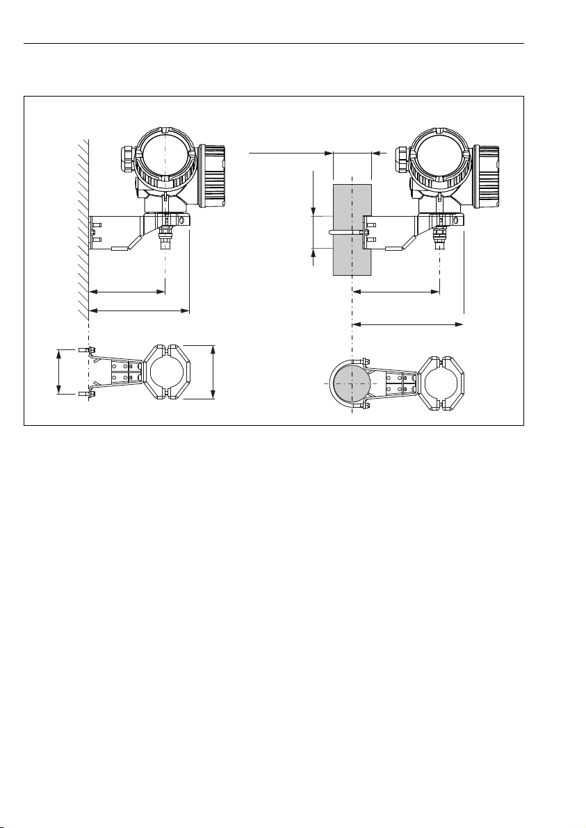
Mounting the electronics housing
122 (4.8)
52 (2)
86
(3.4)
70
(2.8)
127...140
(5...5.51)
161 (6.34)
162...175
(6.38...6.89)
A B
ø42...60
(1.65...2.36)
A0014793
4 Mounting the electronics housing using the mounting bracket; dimensions: mm (In)
A Wall mounting
B Pipe mounting
Connecting the cable
Required tools:
• For the coupling nut at the housing side of the cable: Open-end wrench AF 18mm
• For the coupling nut at the probe side of the cable: 54mm (2.1") hook wrench and 27 mm
(1-1/16") open-end wrench

Levelflex FMP53 HART Mounting
Endress+Hauser 15
3 m (9 ft) / 6 m (19 ft)
rmin = 50 mm (2")
6 Nm (4.42 lbf ft)
A0015103
6.2.3 Turning the transmitter housing
To provide easier access to the connection compartment or display module, the transmitter
housing can be turned:
max. 350°
8 mm 8 mm
1.
2.
3.
A0032242
1. Unscrew the securing screw using an open-ended wrench.
2. Rotate the housing in the desired direction.
3. Tighten the securing screw (1.5 Nm for plastic housing; 2.5 Nm for aluminum or
stainless steel housing).

Mounting Levelflex FMP53 HART
16 Endress+Hauser
6.2.4 Turning the display module
+E
–
1
3 mm
1.
2.
3.
4.
A0032238
1. If present: Loosen the screw of the securing clamp of the electronics compartment cover
using an Allen screw and turn the clamp 90° counterclockwise.
2. Unscrew cover of the electronics compartment from the transmitter housing.
3. Pull out the display module with a gentle rotational movement.
4. Rotate the display module to the desired position: max. 8 × 45° in each direction.
5. Feed the coiled cable into the gap between the housing and main electronics module
and plug the display module into the electronics compartment until it engages.
6. Screw the electronics compartment cover back onto the transmitter housing.
7. Tighten the securing clamp with an Allen screw (torque: 2.5 Nm).

Levelflex FMP53 HART Mounting
Endress+Hauser 17
6.3 Post-installation check
mIs the device undamaged (visual inspection)?
m
Does the device conform to the measuring point specifications?
For example:
• Process temperature
• Process pressure (refer to the chapter on "Material load curves" of the "Technical Information"
document)
• Ambient temperature range
• Measuring range
mAre the measuring point identification and labeling correct (visual inspection)?
mIs the device adequately protected from precipitation and direct sunlight?
mAre the securing screw and securing clamp tightened securely?

Electrical connection Levelflex FMP53 HART
18 Endress+Hauser
7 Electrical connection
7.1 Connection conditions
7.1.1 Terminal assignment
2-wire: 4-20mA HART
8
9
1
+
2
4...20mA
HART
10 mm
Spare part
71108xxx
2- wire level
4-20 mA 4-20 mA
HART
[21]
open
-
1
+2
4-20mA
1-channel overvoltage protection
-
[16]
A
7
B
!
4...20 mA
5
4
12
3
+
–
+
–
#
+
–
4...20 mA
5
4
12
3
+
–
6
#
A0011294
5 Terminal assignment 2-wire; 4-20mA HART
A Without integrated overvoltage protection
B With integrated overvoltage protection
1 Active barrier with power supply (e.g. RN221N): Observe terminal voltage
2 HART communication resistor (≥ 250 Ω): Observe maximum load
3 Connection for Commubox FXA195 or FieldXpert SFX350/SFX370 (via VIATOR Bluetooth modem)

Levelflex FMP53 HART Electrical connection
Endress+Hauser 19
4 Analog display device: Observe maximum load
5 Cable screen; observe cable specification
6 4-20mA HART (passive): Terminals 1 and 2
7 Overvoltage protection module
8 Terminal for potential equalization line
9 Cable entry

Electrical connection Levelflex FMP53 HART
20 Endress+Hauser
2-wire: 4-20mA HART, switch output
1
+
2
4...20 mA
HART
10 mm
Spare part
71108xxx
2- wire
4-20 mA PFS
HART
[02/03]
open
-
A
1
+
2
-
3
+4
-
1
3+
+2
4
4-20mA/
FIELDBUS
4-20mA/
2-channel overvoltage protection
-
-
[17]
B
10
9
8
7
11
+
+
-
-
2
2
3
3
4
4
6
5
5
1
1
4...20 mA
≥250 Ω
3+
3+
4-
4-
+
+
–
–
$
$
%
4...20 mA
≥250 Ω
A0013759
6 Terminal assignment 2-wire; 4-20mA HART, switch output
A Without integrated overvoltage protection
B With integrated overvoltage protection
1 Active barrier with power supply (e.g. RN221N): Observe terminal voltage
2 HART communication resistor (≥ 250 Ω): Observe maximum load
3 Connection for Commubox FXA195 or FieldXpert SFX350/SFX370 (via VIATOR Bluetooth modem)
4 Analog display device: Observe maximum load
5 Cable screen; observe cable specification
6 4-20mA HART (passive): Terminals 1 and 2
7 Switch output (open collector): Terminals 3 and 4
8 Terminal for potential equalization line
Table of contents
Popular Radar manuals by other brands

Endress+Hauser
Endress+Hauser Micropilot S FMR530 Brief operating instructions

Radiodetection
Radiodetection RD1500 Operation manual

Houston Radar
Houston Radar Speedlane Pro quick start guide

Endress+Hauser
Endress+Hauser Levelflex FMP55 Brief operating instructions

Pulsar
Pulsar mmWAVE installation guide

Blickfeld
Blickfeld Qb2 Quick start manual


Carmanah
Carmanah SpeedCheck-15 Replacement guide

Endress+Hauser
Endress+Hauser FOUNDATION Fieldbus Micropilot FMR51 Brief operating instructions

Siemens
Siemens SITRANS LG270 operating instructions

Humminbird
Humminbird CHIRP installation manual

SICK
SICK safeRS operating instructions

Endress+Hauser
Endress+Hauser Micropilot FMR20 Brief operating instructions