enea ICB-72A0003M0A User manual

Quick Installation Guide
1/2,8” Network Camera,
1920x1080, Day&Night, AF
Zoom, WDR, 3.2 - 9 mm, Infrared,
IP67
ICB-72A0003M0A
EN
IT
FR
DE

2
Table of content
Parts supplied ...............................................................................................................5
Part names .....................................................................................................................6
Installation instructions ...............................................................................................7
Cover Opening Alarm and External Alarm Input ..................................................................................................7
Using Grommet..................................................................................................................................................................8
Using RJ45 Easy Cap for Network cable....................................................................................................................8
Recommended cable length into the Junction box base ..................................................................................8
Pan & Tilt adjustments.................................................................................................................................................. 12
Quick Network Setup ..................................................................................................14
Web viewer description .............................................................................................................................................. 15
Player control & Display......................................................................................................................................... 15
PTZ Control.................................................................................................................................................................. 16
User Manual ............................................................................................................................................................... 16
Setup Menu Table ..................................................................................................................................................... 17
Quick Setup .................................................................................................................19
Information ...................................................................................................................................................................... 19
Users ................................................................................................................................................................................... 19
Add ................................................................................................................................................................................ 20
Edit.................................................................................................................................................................................. 20
Delete ............................................................................................................................................................................ 21
Date & Time ..................................................................................................................................................................... 21
Current Time ............................................................................................................................................................... 21
New Time...................................................................................................................................................................... 21
Time Zone.................................................................................................................................................................... 21
Day & Time Display................................................................................................................................................... 22
Network ............................................................................................................................................................................. 22
IPv4 Address ............................................................................................................................................................... 22
IPv6 Address ............................................................................................................................................................... 23
DNS ................................................................................................................................................................................ 23
Further information ....................................................................................................24

3
EN
Safety instructions
General safety instructions
•
• Keep the operating instructions in a safe place for later use.
• Installation, commissioning and maintenance of the system may only be carried out by authorised
individuals and in accordance with the installation instructions - ensuring that all applicable standards and
guidelines are followed.
• Protect the devices from water penetration and humidity, since these can cause lasting damage.
• Should moisture nevertheless enter the system, under no circumstance switch on the devices under these
conditions, instead send them for examination to an authorised specialist workshop.
•
• The device must be protected from excesses of heat, dust, humidity and vibration.
• When separating the system from the voltage supply, only ever use the plug to pull out the cable. Never
pull directly on the cable itself.
• Lay the connecting cables carefully and check that they are not mechanically stressed, kinked or damaged
and that no humidity can penetrate into them.
• In the event of a malfunction, please inform your supplier.
• Maintenance and repairs may only be carried out by authorised specialist personnel.
• The system must be isolated from the power supply before opening the housing.
•
warranty claim.
• Connection cables should always be exchanged through Videor E. Hartig GmbH.
• Use only original spare parts and accessories from Videor E. Hartig GmbH.
• The housing should only be cleaned using a mild domestic cleaning agent. Never use solvents or petrol as
these can permanently damage the surface.
• During installation, it is essential to ensure that the seals provided are correctly installed and that they are
not displaced during installation. Damaged seals must not be installed and will invalidate any warranty.
• The installer is responsible for the maintenance of the enclosure as per the technical data, e.g. by sealing
the cable outlets with silicone.
•
• The devices may only be operated in the temperature range indicated in the data sheet and within the
• The camera may never be pointed directly at the Sun with the aperture open (this will destroy the sensor).
• It is unavoidable that during manufacture and to a certain extent during later use, humidity will be present
may condense inside the housing.
• To avoid this condensation inside the very tightly sealed housing, the manufacturer has inserted silica gel
sachets in the housing of the various camera types.
• It is however a physical given, that these silica gel bags will reach saturation after a certain amount of time.
They should therefore be replaced with new silica gel sachets.
• During installation, it is essential to ensure that the seals provided are correctly installed and that they are
not displaced during installation. Damaged seals must not be installed and will invalidate any warranty.
• A multipolar, easily accessible isolation device should be installed in the proximity of the IR Spotlight, in
order to disconnect the device from the power supply for service work.
• The earth connection must be made according to the low impedance requirement of DIN VDE 0100.
• Subsequent painting of the equipment surface can impair the function.
• Any warranty claim is invalidated by subsequent painting.
• A safety margin of > 1m from the spotlight must be maintained when viewing directly into the IR Spotlight
in a darkened environment.
• Do not look directly at invisible LED radiation using optical instruments (e.g. a reading glass, magnifying
glass or microscope), since this can endanger the eyes, LED Class 1M.
• Operation of the IR spotlight with a defective cover or during repair is prohibited.

4
Class A device note
This is a Class A device. This device can cause malfunctions in the living area; in such an event, the operator may
need to take appropriate measures to compensate for these.
WEEE (Waste Electronical & Electronic Equipment)
Correct Disposal of This Product (Applicable in the European Union and other European countries with separate
collection systems).
This marking shown on the product or its literature, indicates that it should not be disposed with
other household wastes at the end of its working life. To prevent possible harm to the environment
or human health from uncontrolled waste disposal, please separate this from other types of wastes
and recycle it responsibly to promote the sustainable reuse of material resources. Household users
should contact either the retailer where they purchased this product, or their local government
Business users should contact their supplier and check the terms and conditions of the purchase
contract. This product should not be mixed with other commercial wastes for disposal.
Graphical symbols
Please pay attention to the safety instructions, and carefully read through this instruction guide before initial
operation.
Important points of warning are marked with a caution symbol.
iImportant points of advice are marked with a notice symbol.
5
EN
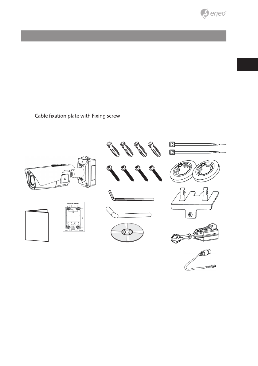
Parts supplied
• Network Camera
• Operating Instruction
• Installation CD
• Mounting Template
• Plastic Anchor: 6 x 30mm (4x)
• Mounting Screw: 4 x 30mm (4x)
• Hex Wrench: 3mm (1x)
• Hinge Pin (1x)
• Cable Tie (2x)
• Grommet (2x)
•
• RJ45 Easy Cap for Grommets
• Video Sub-out Cable (1x)
6
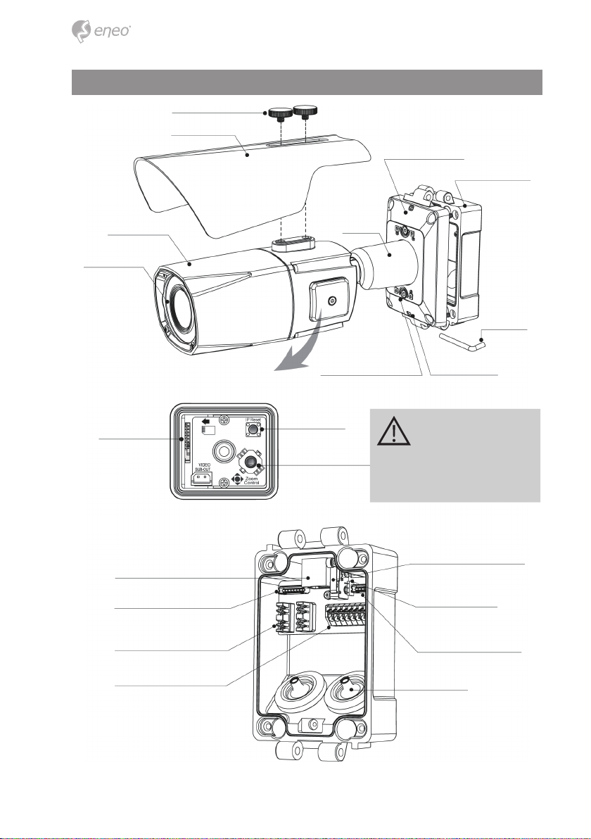
Part names
Junction Box Base
Sunshield bolt
Junction Box Top
Dual window
Bracket
Hinge Pin
Sunshield
2xWater drain
Micro SD Card slot IP Reset
Joy stick for Zoom/
Focus control
2x Lock/Unlock Screw
Body Case
Inside of Opening Cover
Please close the cover
after setting up and
tighten it properly.
Otherwise, moisture
can get inside the
housing.
Junction Box Base
User Network connector
Ethernet from Cam.
Network wiring Connector (LSA)
for user network
Power/ Alarm/ Audio
Cover opening alarm switch
(Sabotage alarm)
Alarm Input selection jumper
Power & I/O from Cam.
Grommet
7
EN
Installation instructions
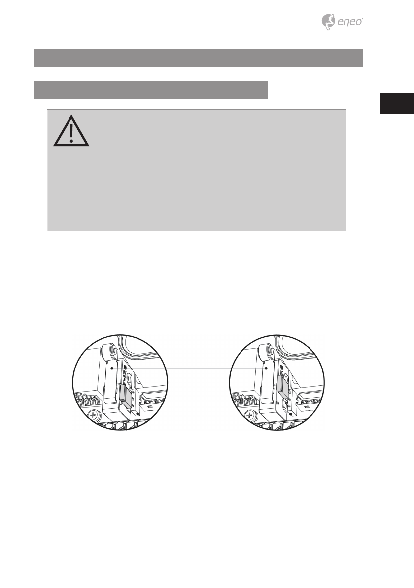
Cover Opening Alarm and External Alarm Input
CAUTION: Cover Opening(Sabotage) Alarm and External Alarm
Input are electrically tied together internally. Alarm contact types,
N.O or N.C are selectable by the Alarm Input Selection Jumper
and the selection types should be matched with Alarm Type in
setup menu.
When both of Cover Opening Alarm and External Alarm Input
are used at the same time, the alarm contact types must match.
Otherwise, alarm malfunctions. When External Alarm Input only
is used with disabling Cover Opening Alarm, remove the jumper
cap of Alarm Input Selection Jumper.
N.O : Alarm is generated when Junction box is OPEN.
N.C : Alarm is generated when Junction box is CLOSED.
Default setting for Alarm Input selection jumper is N.C. It prevents from Alarm is generat-
ing when Junction box is OPEN during installation. Alarm Input selection jumper should
be set to N.O and Event Trigger/Action should be dened to enable Cover opening alarm.
For Cover Opening Alarm, please go to SETUP> Event Rules> Event Processing>
Add Event Trigger should be set to“Alarm In”and then Event Action should be
set as available options
[N.O] [N.C]
Cover opening alarm switch
(Sabotage alarm)
Alarm Input selection jumper

8
Using Grommet
wrap the cable properly as illustrated. If it doesn’t wrap the cable properly,it could cause
the water leakage problem.
Using RJ45 Easy Cap for Network cable
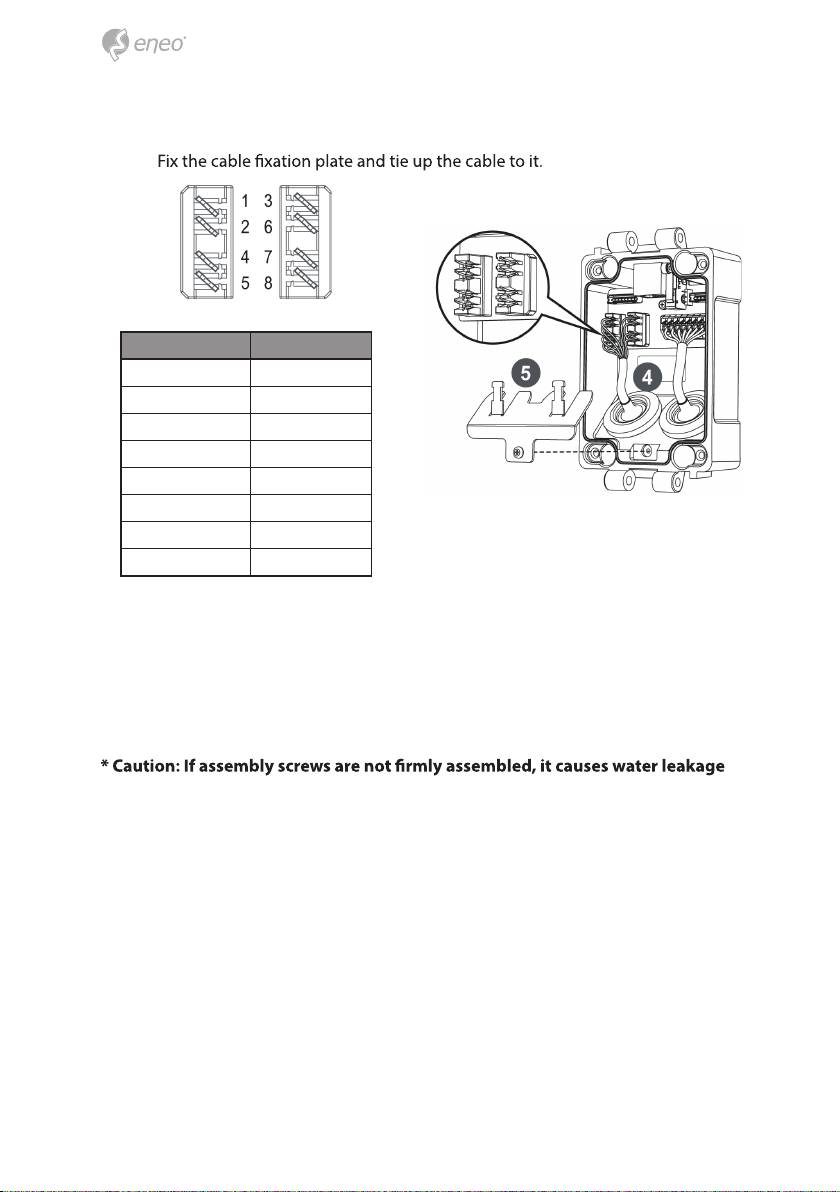
Recommended cable length into the Junction box base
• CABLE with RJ-45 Connector: 70mm~80mm
• CABLE for Network Wiring Connector: 20mm~30mm (excluding cable tripping
section) 8P cable stripping distance: 20mm~30mm
• Power CABLE: 20mm~30mm (excluding cable tripping section) 8P cable stripping
distance: 20mm~30mm

9
EN
Install the mount onto a strong structure.
Prepare the Junction box base and the accessaries for installation.
1. Locate the mounting template at the installation position and drill the ceiling or
wall if needed.
2. Route the Power/Ethernet cables through the grommets from the wall. Insert the
grommets onto the Junction box base.
3.
mounting screws (4x30mm).
10
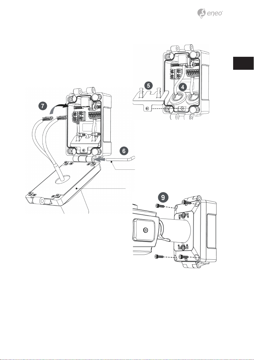
4. Hook up the Power & I/O wires and Network cable to the connectors. Network
cable can be connected to either RJ-45 connector or LSA connectors.
5.
6. Assemble the Junction box top to the Junction box base using a hinge pin. Hinge
can be inserted at either side for convinience.
7. Connects the Power/Ethernet cables from camera.
8. Set Alarm Input Selection Jumper. ( Refer to‘Cover Opening Alarm and External
Alarm Input’)
9. Cover the Junction box top and tighten with assembly screws (4pcs).
Connections to LSA connectors
TIA/EIA 568A TIA/EIA 568B
1. Green-White 1. Orange-White
2. Green 2. Orange
3. Orange-White 3. Green-White
4. Blue 4. Blue
5. Blue-White 5. Blue-White
6. Orange 6. Green
7. Brown-White 7. Brown-White
8. Brown 8. Brown
11
EN
.
10. Set the camera’s orientation and tighten the Lock/Unlock screws using hex
wrench.
11. Open the Opening cover to insert the Micro SD memory or control the zoom/
Focus using joystick.
12. After all the setting, close the Opening cover and tighten it.
13. Put the sunshield to the camera unit and tighten the sunshield bolts.
Connections to RJ-45 connector
Hinge pin
Junction Box Top

12
CAUTION:
Extreme care should be taken NOT to scratch the window in front
of lens. Care should be taken the cable is NOT to be damaged,
kinked or exposed in the hazardous area. Do not expose the
camera directly to a strong light source such as the sun or spot
light.
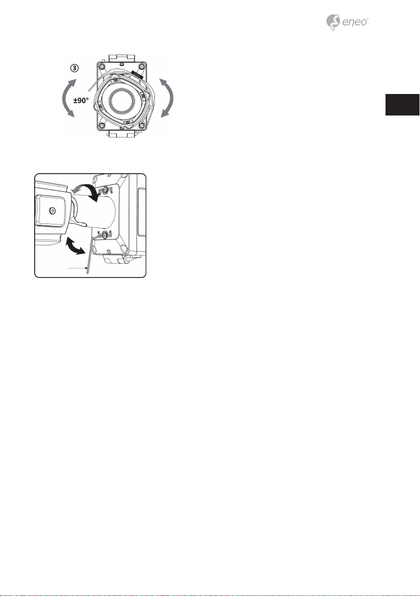
Pan & Tilt adjustments
• Unlock the screw on the camera bracket through using the torque wrench supplied
• Set the camera’s viewing angle then lock the screw on the bracket.
1. Pan limit: Pan is limited to +/- 90°.
2. Tilt limit: Tilt is limited to 0°(2°) min ~ 90° max. for wall(ceiling) installation respec-
tively with reference to the wall(ceiling) when the inclination of camera module is
0°, that is, the image is aligned horizontally.
3. Inclination limit (Horizontal image alignment): Inclination limited to +/-90° max.
on the wall on the ceiling
13
EN
Adjustment of viewing angle with a bracket
Hex wrench
14
Quick Network Setup
1. After the camera is connected to the network, start ‘eneo Site Manager’ tool
(downloadable from www.eneo-security.com).
2. You will get a list of cameras connected to the local network. Highlight your cam-
era in the list and open a context menu with a click of the right mouse button.
3. Select the„Set IP Address [dhcp / static]“ option to open a window for setting the
cameras IP properties. When you are done click the„OK“ button to update the
camera settings.
4. By default the camera is set to DHCP. If there is no DHCP server present in the net-
work the camera will fall back to a default IP address after a while. In this scenario
identical IP addresses.
The network camera‘s default IP address is: 192.168.1.10.
5. Right clicking the device name in the eneo Site Manager will bring up the context
menu. Use the ‘Open Device Web Site’ option to access the camera.
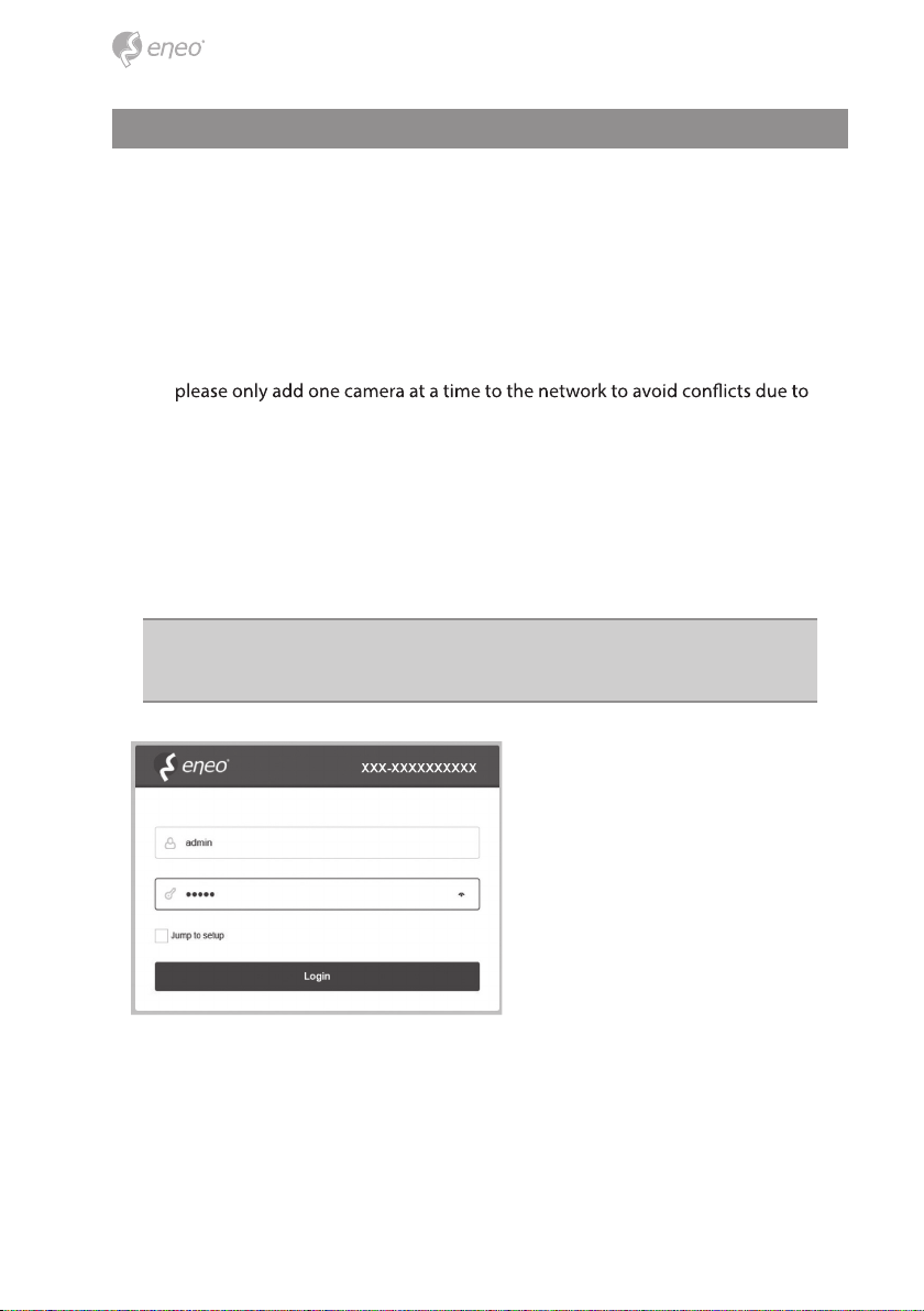
6. The web viewer login page will open up in your default web browser.
In case of Microsoft Internet Explorer install Active-X named VIDEOR E. Hartig
GmbH according to the instruction at the bottom of the browser.
7. Use the default user name and password to log in.
Default user name: admin
Default password: admin
15
EN
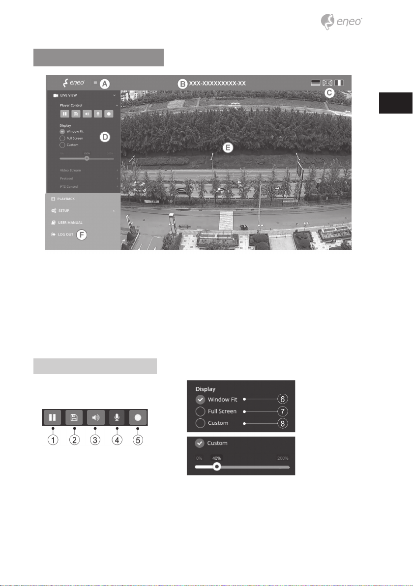
Web viewer description
(A) Menu button : Click the button to show or hide the setup menu bar.
(B) Model name : Show a camera model name connected.
(C) Select Language : Set the web viewer language English, Deutsch or French.
(D) Main setup menu bar : Set the camera or network functions.
(E) Camera monitoring window: Display the currently connected camera view or
function.
(F) Log out and exit the web viewer
Player control & Display
(1) Pause: Pauses the live view.
(2) Snapshot: Captures the image in .jpg format with the current stream resolution.
(3) Speaker: Enables audio to be output to the audio out port.
(4) Microphone: Enable audio to be input from the audio input port.
16
(5) Record: Records the live video in H.264 format to the equipped storage memory
like SD, SDHC or SDXC from the video stream selected in the RECORD menu.
(6)
(7)
returns to the previous view.
(8) Custom: Selects the live view display scale, 0%~200%, by the control bar. 100% is
the original size.
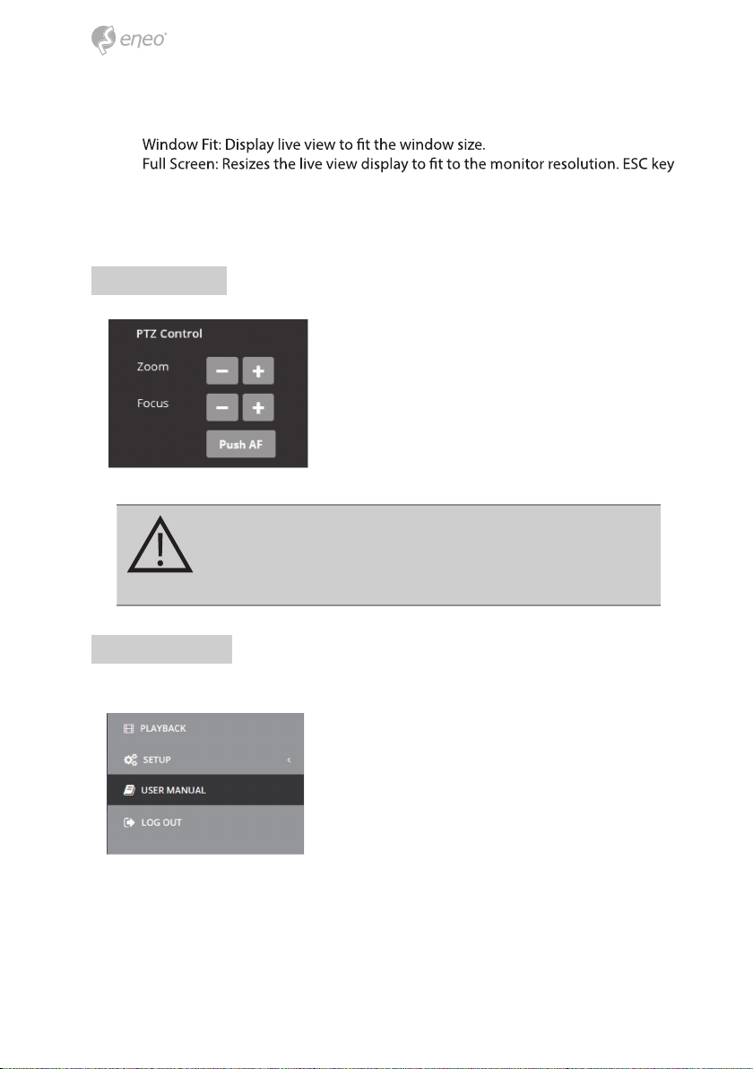
PTZ Control
Used to adjust zoom/focus manually or one-push
focus automatically.
• Zoom: Controls the lens optical zoom in/out for
WIDE & TELE.
• Focus: Adjusts the lens focus manually for NEAR &
FAR.
• Push AF: Gets the lens to focus at the push of a
button.
CAUTION:
• Do not adjust zoom/focus in low light conditions or night
mode. It might cause erroneous focusing.
User Manual
Help the menu function. Click and pop-up the page about current menu description.

17
EN
Setup Menu Table
Category Menu
LIVEVIEW
Player Control Pause, Snapshot, Speaker, Microphone, Record
Display (Window Fit, Full Screen, Custom)
Video Stream Stream1, Stream2, Stream3, Snapshot
Protocol HTTP,TCP, UDP
PTZ Contol Zoom, Focus, Push AF
PLAYBACK Event Search, Timeline Search, Timeline Bar
SETUP
Information General, System Information, Open source Information
Video & Image
Source
Stream1/2/3, Snapshot
Image
Basic
Brightness, Bright-
ness[Night], Saturation, Sat-
uration[Night], Sharpness,
Enable mirror image
OSD
Enable text OSD, Enable
date&time OSD, Enable
zoom&focus OSD, Enable
focus indicate OSD
AE
Mode, Shutter, Iris, AGC,
-
er-less, Motion Deblur
AWB Mode, Cb Gain, Cr Gain
AF Mode, Lens Initialize
Day&Night
Mode, IR LED Control,
Switching time,Threshold,
Gap, Smart IR
DOLWDR DOLWDR(Mode, Level),
Defog (Mode, Level)
BLC BLC (Mode), HLC (Mode,
Level)
DNR 3DNR(Mode, Level)
VerticalView Mode, Rotation
Privacy Mask Color, Name
Digital Zoom Level
DIS Mode, Range, Filter, Auto Center
Audio Compression, Sample rate, Bitrate, InputVolume, OutputVolume, Audio auto activation
on ONVIF access

18
SETUP
Record
Record Overwrite when storage is full, Continuous record setting
Schedule
Storage Format, Remove, Storage Information
PTZ Preset Preset, Home
Event
Triggers Motion, VCA,Tamper, Alarm In, System, Manual, Network,
Timer, Day/Night
Actions Record, Alarm Out, E-Mail, FTP, Video Boost, PTZ Preset,
Rules Event Processing, ONVIF Mapping
System
Security User, HTTPS, IP Filter, ONVIF, Video Stream, Export/Import
Date &Time Current Time, New Time, Time Zone, Date & Time Display
Network TCP/IP, DDNS, RTP, UPnP, Zeroconf, Bonjour
Language English, German , French, Polish, Finnish, Korean
Maintenance Maintain (Restart, Reset, Default), Upgrade, Setup Export,
Setup Import
Log & Report Logs (Database Capacity, Search Condition, Log List), Report
USER MANUAL
LOG OUT
19
EN
Quick Setup
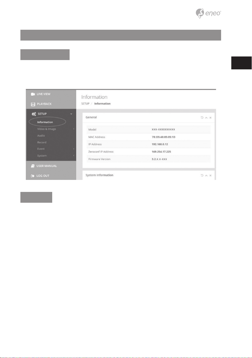
Information
Shows the overall information about the system such as Model name, MAC address, IP
address, Zeroconf, IP address, Firmware version, Server time, Running time, CPU usage,
Inbound/Outbound Bandwidth and Open source list.
Users
Manages the user accounts by names, groups and authorities.
• Mark ENABLE ANONYMOUS VIEWR LOGIN if anyone is permitted to login anony-
mously. Accessing SETUP menu with the anonymous login will exit and require ID/
Password login.
• > USERS : Can be added, edited or deleted.

20
Click the Add, Edit, or Delete button for managing user account.
Add
To add a new user:
1. Click the Add tab, and type a new user name. (1 to 14 alphanumeric characters).
User names are not case sensitive.
2.
Passwords are case sensitive.
3. Select one of the groups you wish to assign to the user.
4. Click the OK button to save the settings and add a new user.
Edit
To edit a user:
1. Select one of the User Names in the User List you want to modify.
Table of contents
Languages:


