ENENSYS Divi Catch RF User manual

DiviCatch RF
Live RF and ASI to
USB2.0 pocket adapter
and stream analyzer
USER GUI E
ENENSYS Technologies
Le Germanium
80 avenue des Buttes de Coesmes
35700 Rennes
FRANCE
Office (+33) 2 99 12 79 06
Fax (+33) 2 99 12 79 05
www.enensys.com
VB is a Trade Mark of the VB igital Video Broadcasting Project (1991 to 1996) – DVB Product ID: 4937/4938
2007 11 - Subject to change without notice – Rev 4.3
Baseband Converters ¨
Network Adapters þ

Table of Content
INTRO UCTION........................................................................................................................... 3
Product Overview..................................................................................................................... 3
Related ocuments................................................................................................................... 3
PC/Laptop minimum requirements.............................................................................................. 4
INSTALLATION............................................................................................................................. 5
Software installation............................................................................................................... 5
Plug iviCatch for the first time (Windows XP or Windows 2000 only)............................................5
Very interesting remarks......................................................................................................... 5
RUNNING IVICATCH SOFTWARE
FOR THE FIRST TIME.................................................................................................................... 6
iviCatch RF – General panel..................................................................................................... 6
iviCatch RF-C – Signal tuning................................................................................................... 7
iviCatch RF-T/H – Signal tuning................................................................................................ 7
iviCatch RF - Monitor & log panel.............................................................................................. 8
iviCatch RF - VB-H Analysis.................................................................................................. 19
Burst structure........................................................................................................................ 20
FER and MFER......................................................................................................................... 20
elta_T information................................................................................................................. 21
RF Analysis............................................................................................................................. 22
iviCatch RF-C........................................................................................................................ 22
iviCatch RF-T/H..................................................................................................................... 25
iviCatch – Record & video panel.............................................................................................. 27
iviCatch RF-T/H – ESG panel................................................................................................. 31
Configurable profiles............................................................................................................... 32
iviCatch RF – GPS option....................................................................................................... 32
External cartographic applications.............................................................................................. 34
iviCatch application and device status..................................................................................... 36
Notes and remarks................................................................................................................. 36
REGULATORY & STATUTORY NOTICES........................................................................................... 37
EMC and safety declaration...................................................................................................... 37
Environmental specifications.................................................................................................... 37
TECHNICAL ATA....................................................................................................................... 38
Interfaces Specifications.......................................................................................................... 38
ANNEX...................................................................................................................................... 39
Installation of VideoLan........................................................................................................... 39
ENENSYS iviCatch RF - Manual Page 2 / 40
DiviCatch RF
User Guide

I N T R O U C T I O N
P r o d u c t O v e r v i e w
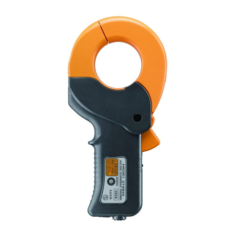
DiviCatch RF refers to all RF-enabled DiviCatch devices. This manual covers
DiviCatch RF-C and DiviCatch RF-T/H devices.
ENENSYS' DiviCatch RF was designed to catch a live modulated signal or an
MPEG2 Transport Stream from any application and turn it into a USB2.0 link to be
received by a laptop equipped. DiviCatch RF is equipped with an RF tuner and a
demodulator for signal analysis. DiviCatch RF also integrates an ASI input to allow
for MPEG2 TS monitoring and analysis.
When connected to an MPEG2 source, DiviCatch is able to record it on the hard
drive of a PC (provided that source is valid), and also to monitor displayed services.
DiviCatch is self-powered. It gets its power from USB bus, thus does not require
any external power supply.
R e l a t e d o c u m e n t s
[1] ETSI EN 300 468 “ igital Video Broadcasting ( VB); Specification for Service Information (SI)
in VB systems.” ( VB-SI)
[2] EN 50083-9 Interfaces for CATV/SMATV Headends and similar Professional Equipment
[3] ETSI EN 300 429 igital broadcasting systems for television, sound and data services;
Framing structure, channel coding and modulation for cable systems
[4] TR 101 891 igital Video Broadcasting ( VB); Professional Interfaces: Guidelines for the
implementation and usage of the VB Asynchronous Serial Interface (ASI).
[5] USB Specification Universal Serial Bus Specification Revision 2.0 (April 27, 2000)
[6] ATSC A65 PROGRAM AN SYSTEM INFORMATION PROTOCOL FOR TERRESTRIAL
BROA CAST AN CABLE
[7] ITU-T J83 igital multi-programme systems for television, sound, data and services for
cable distribution
[8] ETSI EN 300 744 igital Video Broadcasting ( VB); Framing structure, channel coding and
modulation for digital terrestrial television
[9] ETSI EN 302 304 igital Video Broadcasting ( VB); Transmission System for Handheld
Terminals ( VB-H)
[10] ETSI TR 101 290 igital Video Broadcasting ( VB); Measurement guidelines for VB systems
ENENSYS iviCatch RF - Manual Page 3 / 40
DiviCatch RF
User Guide

P C / L a p t o p m i n i m u m r e q u i r e m e n t s
Any PC equipped with USB2.0 interface and an application running on Windows
OS (Windows 2000 or Windows XP), at least PIII @ 300MHz supported by 256 MB
RAM.
epending on bit rates to process and analyze, higher configurations may be
required, especially with DiviCatch RF devices. The more analysis modules are
started, the more memory and CPU are used: Always check CPU and memory
usage. Recommended configuration for all types of streams is CPU @ 1.66GHz and
0,99GB RAM.
epending on bit rates to record, hard drive speed is a determinant factor. For
input bit rates lower than 80Mbps, a 5400 RPM disk is enough. For higher
throughputs, it is recommended to mount a faster disk (7200 RPM or above, with
eventually Serial ATA or SCSI interface).
irectX 9.0 (or higher) library is required so that audio/video services can be
displayed in the Analysis window. irectX 9.0 is provided with Windows XP. It can
also be downloaded and installed from Windows' website.
ENENSYS iviCatch RF - Manual Page 4 / 40
DiviCatch RF
User Guide

I N S T A L L A T I O N
S o f t w a r e i n s t a l l a t i o n
Install DiviCatch software from Companion C . Execute the setup file from the folder ENENSYS
Software\DiviCatch\GUI and follow instructions.
N TE: It is important that no iviSeries device is attached to the computer during the installation.
P l u g D i v i C a t c h f o r t h e f i r s t t i m e (Windows XP or Windows 2000 only)
–Once the installation process has completed, connect the DiviCatch RF device to a USB2.0 port on the
computer using the USB cable shipped with the DiviCatch RF device.
–Windows system finds new hardware and launches a new hardware wizard automatic driver installation
wizard. Choose “No, not this time”, and click Next. Then choose “Install the software automatically”, and
click Next. Continue until installation is complete.
–Wait for a couple of seconds (no need to unplug/replug); Windows system will re-enumerate the
device and will ask for a second driver installation. Same as previous step and continue until
install is complete.
–When driver installation is done, DiviCatch RF led gets red. Then launch the application
(DiviCatch RF led gets orange).
V e r y i n t e r e s t i n g r e m a r k s . . .
•river installation is only valid for the very USB2.0 port the DiviCatch RF device is connected to. If
DiviCatch RF is connected to any other USB2.0 port, Windows system will start another device
enumeration and behave as if a new USB device was detected. Companion C will not be required and
Windows re-enumeration wizard will self complete. In order to be able to use the DiviCatch RF device
from any USB2.0 port, installation must be done for each USB2.0 port.
•DiviCatch application is not workable when no DiviCatch device is connected to the USB2.0 port of the PC.
•If you have purchased the GPS option, check the “GPS drivers” box at installation time without the GPS
receiver being connected to the PC.
•Meaning of LE colors on device:
OFF: no driver installed, happens when DiviCatch RF is plugged for the 1st time.
Red: river installed and device is recognized
Orange: DiviCatch application is launched (SW and device are connected), DiviCatch is ready to run
Green: receiving a stream (slow blink=188, fast blink=204 bytes/packet TS)
ENENSYS iviCatch RF - Manual Page 5 / 40
DiviCatch RF
User Guide

R U N N I N G I V I C A T C H S O F T W A R E
F O R T H E F I R S T T I M E
D i v i C a t c h R F – G e n e r a l p a n e l
This panel gives information about the device attached to the PC via the USB2.0
link in order to:
•Check graphically if receiving one stream (arrow blinks green meaning
that the device is synchronized and receiving TS packets),
•Get general information such as DiviCatch RF Serial Number and FW/SW
versions,
•Check through a single click if a new software release is available for
your product (requires an Internet connection to access Enensys' web
site).
Sample General Panel for DiviCatch RF-C
ENENSYS iviCatch RF - Manual Page 6 / 40
DiviCatch RF
User Guide
Blinks green when
receiving stream
packets ASI input)
General
information
Blinks green when
locked to a modulated
signal RF input) Check if new release is
available requires
Internet connection)

RF and ASI inputs
All DiviCatch RF feature both an ASI input and an RF input. Either can be used
to receive a stream (live for RF and baseband for ASI) and analyze or process it.
Switching between RF and ASI inputs is operated through the general panel by
graphically selecting the input to be used (click on the arrow).
D i v i C a t c h R F - C – S i g n a l t u n i n g
The DiviCatch RF-C must lock the cable input signal. The Tuning section in the
RF Cable panel lets you specify all the necessary information to tune the device to
the desired signal.
●Mode: specify the Annex used (A, B or C) to modulate the signal
●Modulation: specify the type of modulation applied to the signal
(default value: automatic for auto-detection)
●Symbol rate: specify the symbol rate (expresses in Msymbols/s)
●RF Frequency: specify the frequency on which the signal is
received (expressed in MHz)
Then, click the “Tune” button. If the device is tuned to a signal,
the Tuning led turns green and the message Front-End locked is
displayed. On the DiviCatch RF-C device, the led also turns to blinking green.
Note: All frequencie entered are kept in hi tory for quicker reu e. Thi information
i aved into the profile, allowing you to have your own frequencie on different
tation .
D i v i C a t c h R F - T / H – S i g n a l t u n i n g
Note: The portable antenna provided with the product i intended a a “ tarter”
antenna. Depending on environmental condition and network topology, thi
antenna may not be powerful enough to tune to all ignal . If thi i the ca e, it i
recommended that a more powerful antenna (offering gain) i u ed.
The DiviCatch RF-T/H must lock the VB-T or VB-H input signal. The Tuning
section in the RF-T/H panel lets you specify all the necessary information to tune
the device to the desired signal.
●Channel bandwidth: Specify the channel bandwidth
occupied by the multiplex you would like to connect
to. Choose between 5, 6, 7 or 8 (expressed in MHz).
●RF Frequency: Specify the frequency on which the
signal is received (expressed in MHz).
Then, click the “Tune” button. If the device is tuned to
a signal, the Tuning led turns green and the message
Front-End locked is displayed. On the DiviCatch RF-
T/H device, the led also turns to blinking green.
ENENSYS iviCatch RF - Manual Page 7 / 40
DiviCatch RF
User Guide

●Priority: If hierarchical modulation is used on the channel to which the
DiviCatch RF-T/H is locked, this drop-down list is used to specify which
priority should be monitored.
Note: All frequencie entered are kept in hi tory for quicker reu e. Thi information
i aved into the profile, allowing you to have your own frequencie on different
tation .
D i v i C a t c h R F - M o n i t o r & l o g p a n e l
•Real time TS Analysis, providing PSI/PSIP/SI table parsing
•Log, providing error or information messages on device or stream.
•Monitoring, providing 4 types of information:
•Real-time graph of bitrate information,
•ETR290 error measurement,
Note: Both monitoring features can be configured through the Settings tab.
•Pre-defined alarms on MPEG2-TS and VB-H layer,
•PCR Jitter (Accuracy) graph.
Real time TS analysis
In the TS Analysis section, information is provided on Programs, PI s and specific table parsing.
ENENSYS iviCatch RF - Manual Page 8 / 40
DiviCatch RF
User Guide

Analysis modes: DVB and ATSC
Two modes for interpreting MPEG2-TS signalling are available: VB and ATSC. VB
Mode is used for interpreting PSI/SI signalling, and ATSC mode is used for interpreting
PSIP/SI signalling. Switching between modes is performed through the TS Mode drop-
down list
General use
All tabs can be detached for a more comfortable viewing through a drag-and-drop of
the tab outside of the TS analysis section. This viewing is especially useful to real-
time monitor a specific table at the same time as a different table or RF parameter.
All tabs can be detached and become independent windows. Close a detached tab to
reintegrate it to the list of tabs inside the TS Analysis section.
“Programs” tab displays all the services
contained within the stream. In this
case, 3 programs are detected
(“Cambodia”, “Kenya” and “USA”
video). Several information are given
such as PI , stream_id, scrambled or
not...
DVB Mode (PSI/SI Signalling)
Other tabs provide advanced analysis. S T, CAT, BAT, NIT, T T and TOT tabs provide PSI/SI table
parsing.
The MIP tab provides parsing of Mega Frame Initialization Packets that are used to synchronize all
transmitters making up a single frequency network.
Real time PI monitoring Network Information Table analysis
ENENSYS iviCatch RF - Manual Page 9 / 40
DiviCatch RF
User Guide

Service escription Table analysis Conditional Access Table analysis
Bouquet Association Table analysis Mega Frame Initialisation Packet analysis
(including real-time Synchro Time Stamps info)
Note: Not relevant for Cable-modulated ignal
Time and ate Table
Embedded UTC time and date stamp in the TS.
Time Offset Table
Embedded indication of local time offset
The last tab, “INT” provides information about all
the parameters contained inside the IP/MAC
Notification Table, which is a VB-H specific table
providing a description of IP streams contained
within the multiplex.
Note: Only available for DVB-H formatted ignal
ENENSYS iviCatch RF - Manual Page 10 / 40
DiviCatch RF
User Guide

ATSC Mode (PSIP/SI Signalling)
Some signalling tables are common in ATSC mode and VB mode: CAT and NIT.
The follwing tables, specific to PSIP signalling, are available for parsing in ivicatch application.
MGT (Master Guide Table) STT (System Time Table)
RRT (Rating Region Table)
CVCT (Cable Virtual Channel Table)
How to use Log information?
Log view
By default, log information consists of the log view in the Monitoring
& Log panel. This view can store up to 1,000 messages. This log view
ENENSYS iviCatch RF - Manual Page 11 / 40
DiviCatch RF
User Guide

can be cleared (Clear Log View) or saved (Save Log View).
epending on the level of information required,
the type of messages to be displayed can be
selected. Also, for the comfort of viewing, log font
color can also be selected for each level of log
information.
●Click Config Log. A “Log configuration”
window opens.
●Select the level of information to be logged: Check each level for which
you would like to view log messages. “Error” (Stream reception errors,
etc.), “Information” (stream reception info, settings changes, etc.),
“ETR290” (ETR290 logs requested individually from the ETR290 tab),
“GPS alarms” (GPS log information, only available with DiviCatch RF-
T/H GPS option).
●Click the colored square at the right of the log level. A color selection
dialog opens. Choose the color to be used for the associated state.
●Click Ok. The “Log configuration” window closes. Settings are applied.
Log file (Continuous monitoring)
A log file feature is also available for continuous monitoring needs.
●Click Config Log. A “Log configuration” window opens.
●As for the log view (see previous section), select the level of information
to be logged.
●Check the “Use log file” box.
●Enter a path and file name for the log files to be created.
●Choose between logging file size and duration for the creation of a new
log file. For example, choosing a “Max file size” of 1MB will create a new
log file every time 1MB is reached. File names are incremented with
numbers (eg, file_name1.log, file_name2.log, etc.)
Note: Log file will be created a long a the U e log file box i checked.
To top the logging of information, open the log configuration dialog and
ENENSYS iviCatch RF - Manual Page 12 / 40
DiviCatch RF
User Guide

uncheck “U e log file”.
●Click Ok. The “Log configuration” window closes. The log file is created.
How to Monitor MPEG2-TS streams?
Settings
•ETR290 Setting
ETR290 settings window is used to set thresholds for raising errors on ETR290
parameters. Min and Max possible values are indicated for reference. The nominal
value correpsonds to the default value (most often the value recommended in the
TR 101 290 VB Guidelines).
To change your personalized thresholds back to VB standard / default values, click
the “Restore efault” button.
•Monitoring Setup
Monitoring setup window is used to personalize the refresh frequency of the
bitrate monitoring graph. Smoothing changes the frequency at which data is
updated (default is “No smoothing” at 1 second). Length changes the total time
monitored in the graph (default is 1 minute). When length parameter is changed,
smoothing is changed accordingly.
NOTE: When monitoring setup is changed, bitrate monitoring graphs are reset.
ENENSYS iviCatch RF - Manual Page 13 / 40
DiviCatch RF
User Guide

Monitoring
Monitoring section's aim is to provide a graphical view of the different services.
Several types of bitrates can be displayed:
Overall bitrate is the pipe allocated for the services listed.
Net bitrate is the sum of all services detected, including PSI/SI tables.
Obviously, net bitrate cannot be greater than overall bitrate.
Drag & Drop: In addition to Overall and net bitrate, you can visualize the
instant bitrate of one or more services (TS streams) using the Drag & Drop
function: Click on one of the services (“Programs” tab, “TS analysis” section), drag
this service until you reach the “Monitoring” window, and drop it. Instant bitrate will
appear. In case higher resolution is required (z-scale) for the dragged & dropped
service, just mask Overall bitrate and/or Net bitrate.
Masks instant bitrate graphical view
Indicates that associated bitrate stream is hidden.
eletes associated TS stream previously added using the rag& rop function.
ETR290
ETR290 is standardized guidelines issued by the VB organization for
measurements in VB systems. These guidelines are intended to provide an
exhaustive overview of elements that matter for the transmission of a stream. All
parameters tested in ETR290 are split over three priorities. First-level priority lists a
basic set of parameters which are considered necessary to ensure that the TS can
be decoded. Second-level priority lists additional parameters which are
recommended for continuous monitoring. And third-level priority lists further
optional parameters covering varied interests.
To start ETR290 monitoring on the stream received, click “Start Monitoring”. The
ETR290 analysis starts and is real-time based. As soon as an error is detected, the
ENENSYS iviCatch RF - Manual Page 14 / 40
DiviCatch RF
User Guide

LE of the corresponding parameter turns to red, and the counter increments.
If further information is needed on a specific parameter, it is possible to raise a log event for each
error raised. Check the log box corresponding to the parameter requested. Then, each time an error
raised (second-based), a message appears in the log window with the following format:
hh:mm:: Name_Of_Error (number of error in the econd) on packet(s) #packet_number
Time for the error is based on the clock of the workstation attached to the iviCatch device.
NOTE: The packet number indicated in the log message is given for estimation purposes : It is
accurate at +/- 100 packets.
To stop ETR290 monitoring, click “Stop Monitoring”.
To start a new monitoring, you can either resume and add up to all existing errors, or reset existing
monitoring by clicking “Reset All Counters”.
For detailed information on ETR290 parameters, please refer to document TR 101 290 from ETSI at
http://webapp.etsi.org/action/PU/20010515/tr_101290v010201p.pdf.
PCR Jitter
A PCR jitter graph showing PCR Accuracy is available from the PCR tab in the Monitoring section.
NOTE: ETR290 Monitoring must be started to view the PCR jitter graph. PCR Jitter is not available
on VB-H formatted signals as there are no PCRs in VB-H.
●First, from the PI list, select for which PI you would like to monitor the PCR Jitter. If the list
of PI s is not available, click Update to refresh the PI s on the current stream. The graph starts
automatically.
NOTE: The first 5 seconds of PCR graph are not valid for measurement: They correspond to
initialization time.
ENENSYS iviCatch RF - Manual Page 15 / 40
DiviCatch RF
User Guide

●Select the Zoom pre-set to be used for watching PCR jitter: 1 second, 5 seconds, 10 seconds,
30 seconds or 1 minute.
●To access detailed information on a specific PCR, pass the mouse over the
line and point representing the PCR. etailed information on the accuracy
and PCR repetition is available. Minimum and maximum PCR accuracy over
the monitored period are also displayed. Passing the mouse on the PCR graph freezes the
display for more convenient browsing.
NOTE: To zoom in and out on the upper graph, click the graph and then use the scroll wheel
of your mouse to zoom in and out.
●The graph at the bottom shows PCR history over last 10 minutes. To navigate through the
history, switch from real-time to history mode in the PCR jitter view
mode. The zoom range on the history graph can now be moved along the
history graph to monitor past PCRs: etails of the zoomed area are
shown in the upper graph.
NOTE: The zoom range for the history graph is also based on the zoom pre-set.
●A graph showing density of PCRs based on their accuracy is also available thourgh a click on the
isplay density button. The density histogram displays instead of the history graph.
For example, this graph shows that the majority of PCRs over the period monitored had an accuracy
between -100 and 100ms.
ENENSYS iviCatch RF - Manual Page 16 / 40
DiviCatch RF
User Guide
PCR real-
time graph
PCR history
graph PCR detailed
information
Switch PCR
density/PCR
history
Zoom
pre-sets

Alarms
The Alarms tab offers continuous monitoring on varied aspects of the transport stream.
NOTE: If min and max values are kept to default value None, the alarm is disabled.
Bitrate monitoring
The Bitrate monitoring section of Alarms is used to monitor real-time bitrate.
Two predefined alarms on Net bitrate (that means overall bitrate minus stuffing) and Stuffing
bitrate are shown by default. It is also possible to add a bitrate monitoring on specific PI s.
●First, click Start bitrate monitoring.
●Specify the minimum and/or maximum values defining the range in which your bitrate should
be considered as correct.
NOTE: Stuffing bitrate corresponds to monitoring the bitrate of PI 0x1FFF (or 8191). This measure
is especially useful for monitoring streams on which statistical multiplexing is used. It helps you
validate that you net bitrate does not come too close to your overall bitrate allowed.
●If need to monitor one or more specific PIDs, click Add PI . A new line appears, showing a
drop-down list contaning all PI s of the MPEG2-TS. Select a PI , and specify the bitrate range.
To add further PI s, repeat the same operation. To remove a PI monitoring, choose Remove
from the drop-down list.
●To access detailed information or keep a trace, it is possible to generate a log message upon
each error detected. For that, check the check box located at the right-hand side of the
counter. Log message information will include the actual bitrate detected outside the range.
●Monitoring starts as soon as a min or max value has been set. Upon the first value detected out
of the defined ranges, LE turns red and counter is set to 1. Upon every further error detected,
counter increments.
Transport and RF consistency monitoring
These alarms are used to check the consistency of the information conveyed on the transport layer
and on the transmission layer. If any deviation is detected between both information, an error is
detected (first LE turns red, then counter increments upon each error).
●To start this monitoring, click Start checking consistency.
ENENSYS iviCatch RF - Manual Page 17 / 40
DiviCatch RF
User Guide

●To access detailed information or keep a trace, it is possible to generate a log message upon
each error detected. For that, check the check box located at the right-hand side of the
counter. Log message information will include the element on which a deviation has been
detected (eg, code rate, hierarchy, etc.).
NOTE: NIT and MIP consistency validation scheme is only available if MIP packets are detected
(SFN networks). NIT and RF consistency validation scheme is only available for a signal received live.
Burst data monitoring
Burst data monitoring is only relevant for VB-H-formatted streams. These alarms help you
automatically validate the output of a head-end.
●First, click Start burst data monitoring.
●Specify the minimum and/or maximum values defining the range in which the values should be
considered as correct.
ENENSYS iviCatch RF - Manual Page 18 / 40
DiviCatch RF
User Guide

●To access detailed information or keep a trace, it is possible to generate a log message upon
each error detected. For that, check the check box located at the right-hand side of the
counter. Log message information will include actual values detected outside the range as well
as the PI on which the error occurred.
●Monitoring starts as soon as a min or max value has been set. Upon the first value detected out
of the defined ranges, LE turns red and counter is set to 1. Upon every further error detected,
counter increments.
Fec presence
This alarm checks the presence of FEC data on all bursts.
Burst duration
This alarms checks the total duration of all bursts.
Burst size
This alarm checks the total size (MPE + FEC) of all bursts.
Off-time
This alarm checks the off-time, that means the total time between two bursts on all PI s.
Jitter
This alarm checks jitter on all bursts. Following VB recommendations, jitter should not exceed
10ms in order to maximise power saving on the battery of the receiver.
Jitter Alarm is calculated from the minimum claimed delta-t. For further information, refer to
page 21.
NOTE: This alarm is also useful to detect bursts arriving “too early”, that means bursts arriving
before the time interval defined through delta-t information. For that, minimum should be set to 0.
MFER
This alarm checks value of MPE-FEC Frame Error Rate on all bursts (refer to page 20 for further details).
FER
This alarm checks value of Frame Error Rate on all bursts (refer to page 20 for further details).
D i v i C a t c h R F - D V B - H A n a l y s i s
NOTE: The VB-H analysis panel is only available with the DiviCatch RF-T/H device.
The VB-H analysis panel enables real-time bursts visualization, and a smart
comparison between values received and those supposed to be received (contained
within MPE header).
In order to monitor one PI (one VB-H service), it is necessary to:
•place the mouse over the window where bursts are scrolling. From now,
scrolling stops.
ENENSYS iviCatch RF - Manual Page 19 / 40
DiviCatch RF
User Guide

•Select the burst to be monitored (simply place the mouse over it).
Information such as off-time, burst duration, Fec columns, etc. will be
displayed.
B u r s t s t r u c t u r e
As seen above, a comparison between theoretical FEC rate and the one received
is performed for selected PI : Here, MPE ata Columns = 128 instead of 191, FEC
Columns = 63 instead of 64, which results in a error of -0.9%.
F E R a n d M F E R
Frame Error Rate (FER) is the ratio of transmitted bursts containing errors
during a specified period. A burst is marked erroneous if any TS-packet within the
burst is erroneous.
MPE-FEC Frame Error Rate (MFER) is the ratio of uncorrectable MPE-FEC
frames received during a specified period. An uncorrectable MPE-FEC frame is a
ENENSYS iviCatch RF - Manual Page 20 / 40
DiviCatch RF
User Guide
Select the burst to be monitored
off-time
Burst
duration
MPE/MPE-FEC section
analysis
Table of contents

